kevarek
-
Commutation with hall feedback
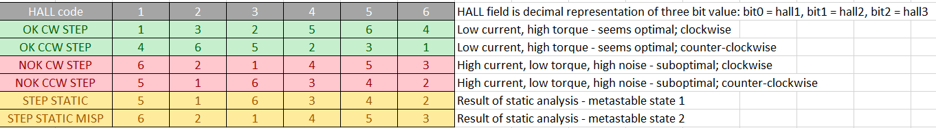
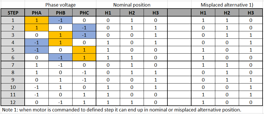
02/23/2022 at 08:59 • 0 commentsSo I have learned that static analysis of step vs hall code will not result with usable table for commutation. Here is the table that is actually useful:
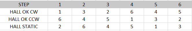
Same table as above but sorted by step (sixstep algorithm):
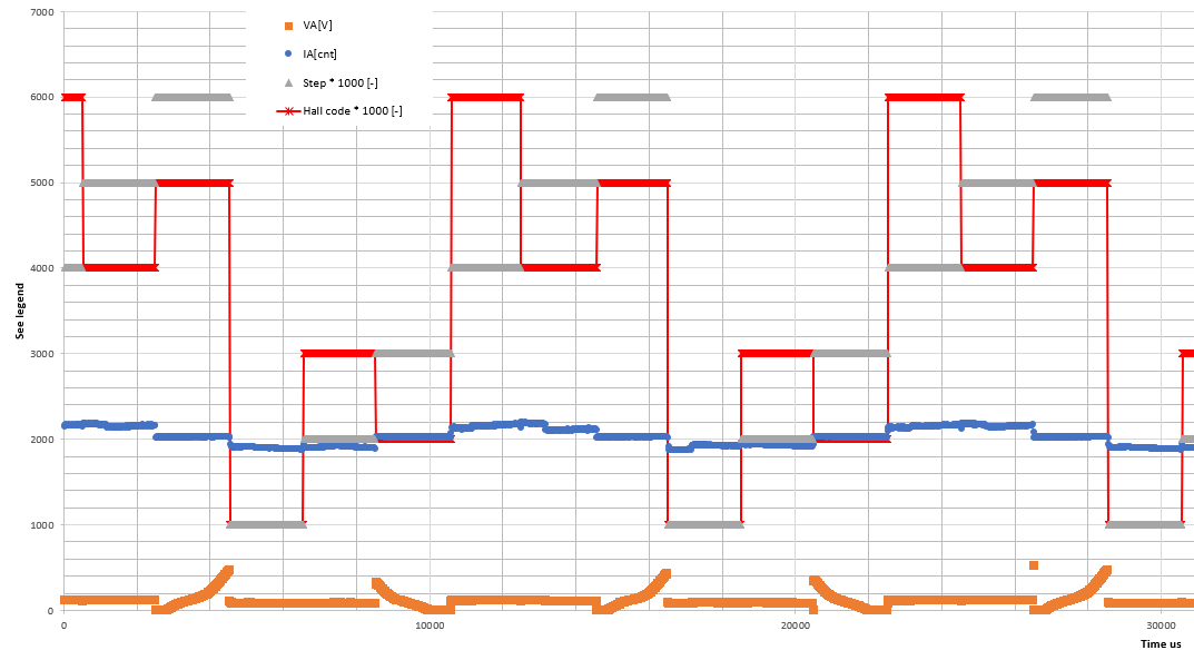
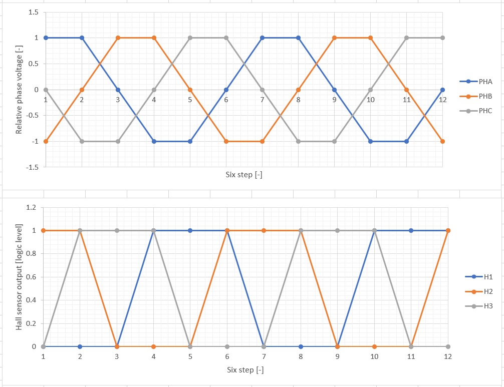
Example of waveforms during OK CW operation (this was data source to create tables above) as acquired synchronously with switching frequency (50 kHz, sampling time at 90 % of switching period): -
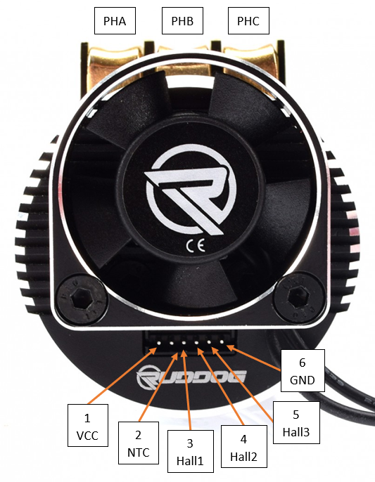
Sensor connector pinout
02/13/2022 at 13:18 • 0 commentsPin 1: Supply voltage (both 3V3 and 5V tolerant).
Pin 2: NTC thermistor output (with respect to GND). 10kOhm @ 25 °C; Beta unknown for now.
Pin 3: Hall 1 output. Open drain. Seems to be related to Phase A.
Pin 4: Hall 2 output. Open drain. Seems to be related to Phase B.
Pin 5: Hall 3 output. Open drain. Seems to be related to Phase C.
Pin 6: Common ground.
-
Hall sensor outputs
02/13/2022 at 13:10 • 0 commentsTable with hall sensor output voltage relative to phase voltage (aka six step configuration - current step). Zero phase voltage indicates that phase is not driven by transistor half-bridge.
Visual representation of table above.
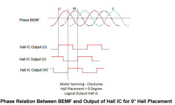
Hall sensors seem to be aligned in such a way that when any of hall outputs change state, commutation event shall occur (sometimes referred as 0° orientation with respect to phase zero crossing):
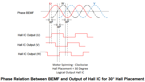
Im not sure what is the benefit but apparently the other option might be 30° orientation (not relevant for this motor):
Source: Texas Instruments - SLAA695.
RUDDOG RP691 2200kV characterization
Since datasheet for this BLDC motor is not available, I will try to characterize its properties and share it here.