 Kutluhan Aktar
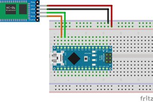
After perusing different LoRa module datasheets, I decided to employ the RYLR998 LoRa (transceiver) module since I wanted to make this project as compact as possible. The RYLR998 LoRa module provides ultra-long range spread spectrum communication with high sensitivity and high interference immunity while minimizing current consumption. Also, this module has a built-in antenna and supports AT commands via serial communication. You can inspect the product datasheet from here.
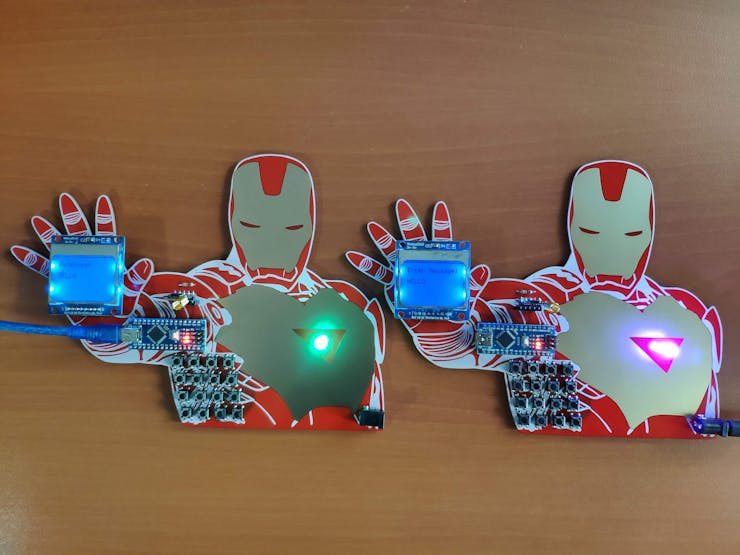
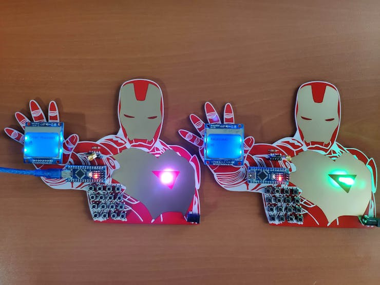
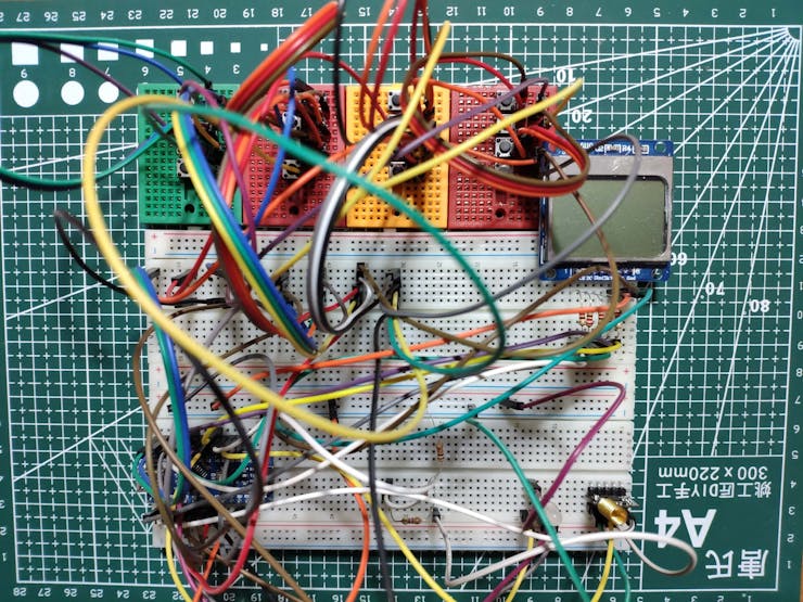
After connecting the RYLR998 module to the Arduino Nano, I utilized a Nokia 5110 screen and designed a custom 4x4 keypad with pushbuttons to obviate the need for sending and displaying text messages via the serial monitor. Finally, I added a 5mm common anode RGB LED to indicate different menu options and message notifications.
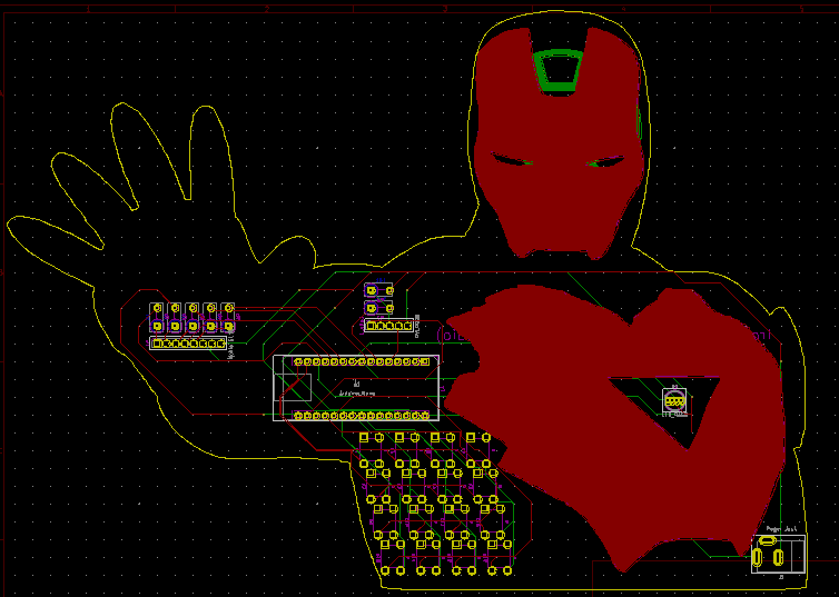
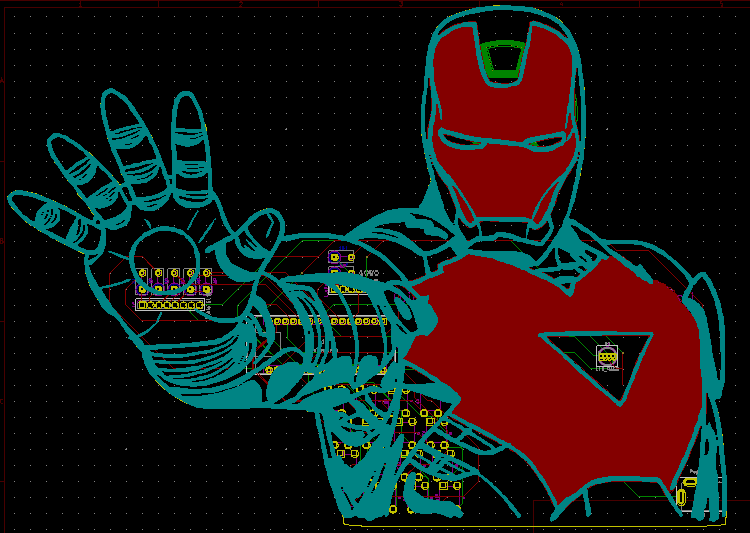
After completing wiring on a breadboard and testing the code for two LoRa-based walkie-talkies (two-way radios), I designed an Iron Man-inspired PCB for this project. I thought Iron Man was germane to my vintage walkie-talkie theme due to a scene from Iron Man 3 near the end of the movie, in which all remaining armors communicate with each other via radio waves covertly. Even though radio is seldom utilized by Iron Man in comics pages, I was inspired by the movie to design Iron Man-themed walkie-talkies (two-way radios) after recently rewatching it :)
Huge thanks to PCBWay for sponsoring this project.
Also, huge thanks to REYAX for sending me the RYLR998 LoRa modules.

Step 1: Designing and soldering the Iron Man Walkie-Talkie (Two-Way Radio) PCB
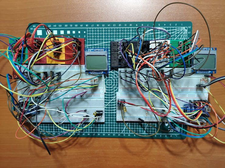
Before prototyping my Iron Man-themed PCB design, I tested all connections and wiring with the Arduino Nano and the RYLR998 LoRa module for two walkie-talkies (two-way radios).
Then, I designed the Iron Man Walkie-Talkie (Two-Way Radio) PCB by utilizing KiCad - inspired by the invincible and legendary Iron Man :) I attached the Gerber file of the PCB below. Therefore, if you want, you can order this PCB from PCBWay to create your LoRa-based walkie-talkies (two-way radios) so as to transmit and receive text messages.
Click here to inspect and order this PCB directly on PCBWay.


First of all, by utilizing a soldering iron, I attached headers (female), resistors (1K, 4.7K, 10K), pushbuttons (6x6), a 5mm common anode RGB LED, and a power jack.
Component list on the PCB:
A1 (Headers for Arduino Nano)
LoRa_1 (Headers for RYLR998 LoRa Module)
S1 (Headers for Nokia 5110 Screen)
D1 (5mm Common Anode RGB LED)
K1, K2, K3, K4, K5, K6, K7, K8, K9, K10, K11, K12, K13, K14, K15, K16 (6x6 Pushbutton)
R1, R2, R3, R4, R5 (1K Resistor)
R6 (10K Resistor)
R7 (4.7K Resistor)
J1 (Power Jack)


Since I needed two Iron Man-themed walkie-talkies (two-way radios) so as to manage to transmit and receive text messages simultaneously, I soldered components to two PCBs.

Step 2: Configuring and initializing the RYLR998 LoRa module
Since the RYLR998 LoRa (transceiver) module requires to be adjusted to transmit and receive text messages simultaneously, I needed to configure each RYLR998 LoRa module with specified settings and addresses. Fortunately, I was able to configure RYLR998 modules effortlessly with the supported AT command list via serial communication.
To configure the RYLR998 modules and send text messages, I utilized the AT commands as follows. You can inspect all available AT commands from here.
#️⃣ Use the AT+ADDRESS command to specify the RYLR998 LoRa module address while transmitting and receiving text messages.
AT+ADDRESS=<Address>
<Address>=0~65535 (default 0)
#️⃣ Use the AT+NETWORKID command to set the LoRa network ID of the RYLR998 module. Setting the correct LoRa network ID is crucial since only the RYLR998 modules with the same LoRa network ID can communicate with each other.
AT+NETWORKID=<Network ID>
<Network ID>=3~15, 18 (default 18)
#️⃣ Use the AT+BAND command to set the...
Read more »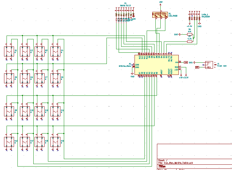

 Silícios Lab
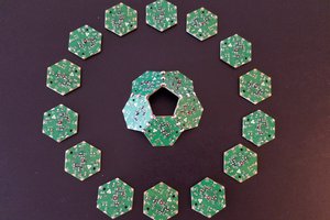
 Hexabitz
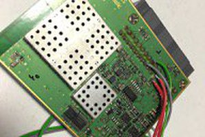
 Saabman
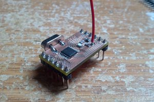
 Daniel Hankewycz
Please feel free to leave a comment here if you have any questions or concerns regarding this project 😃