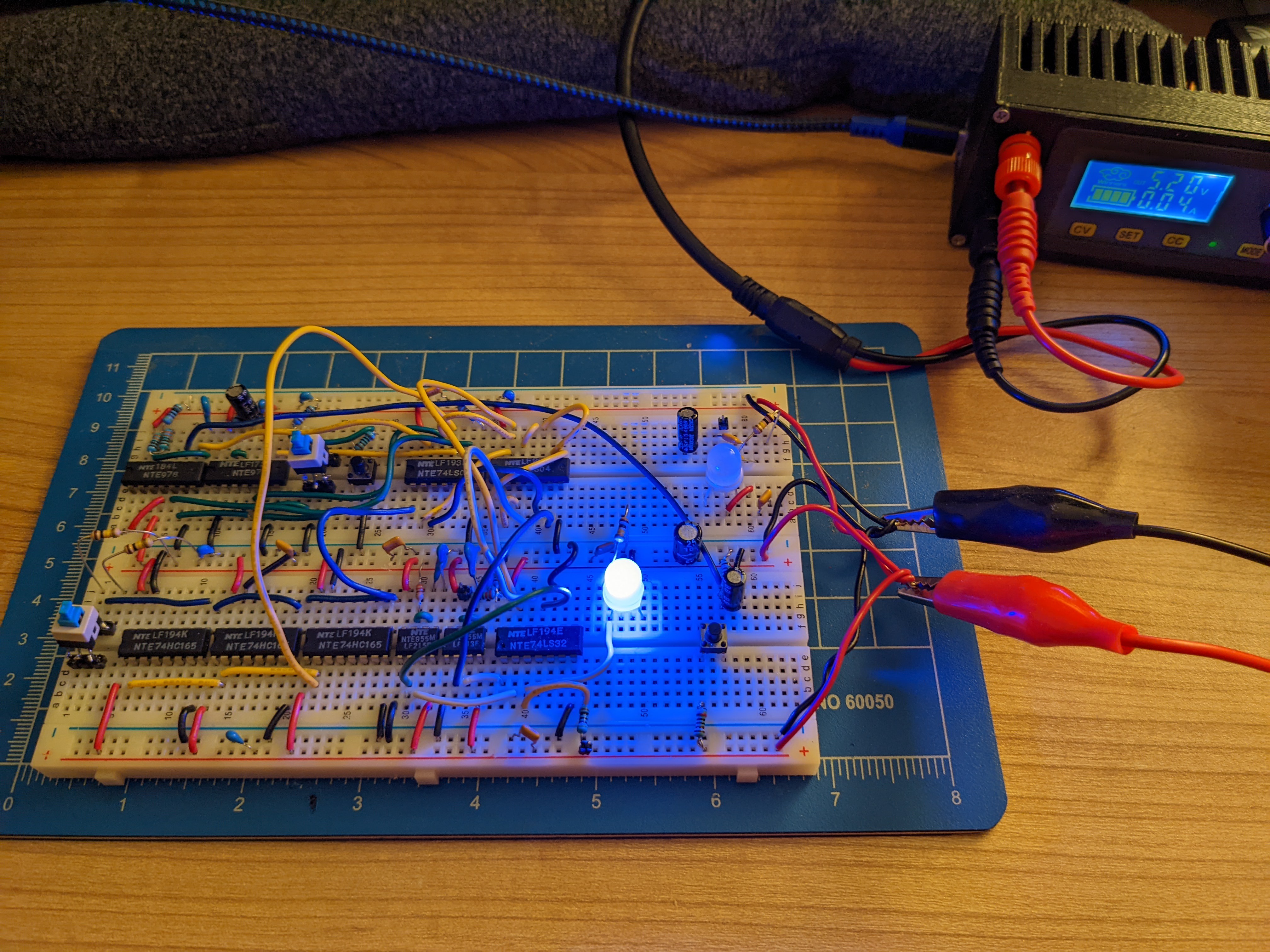
-
Well there's yer problem
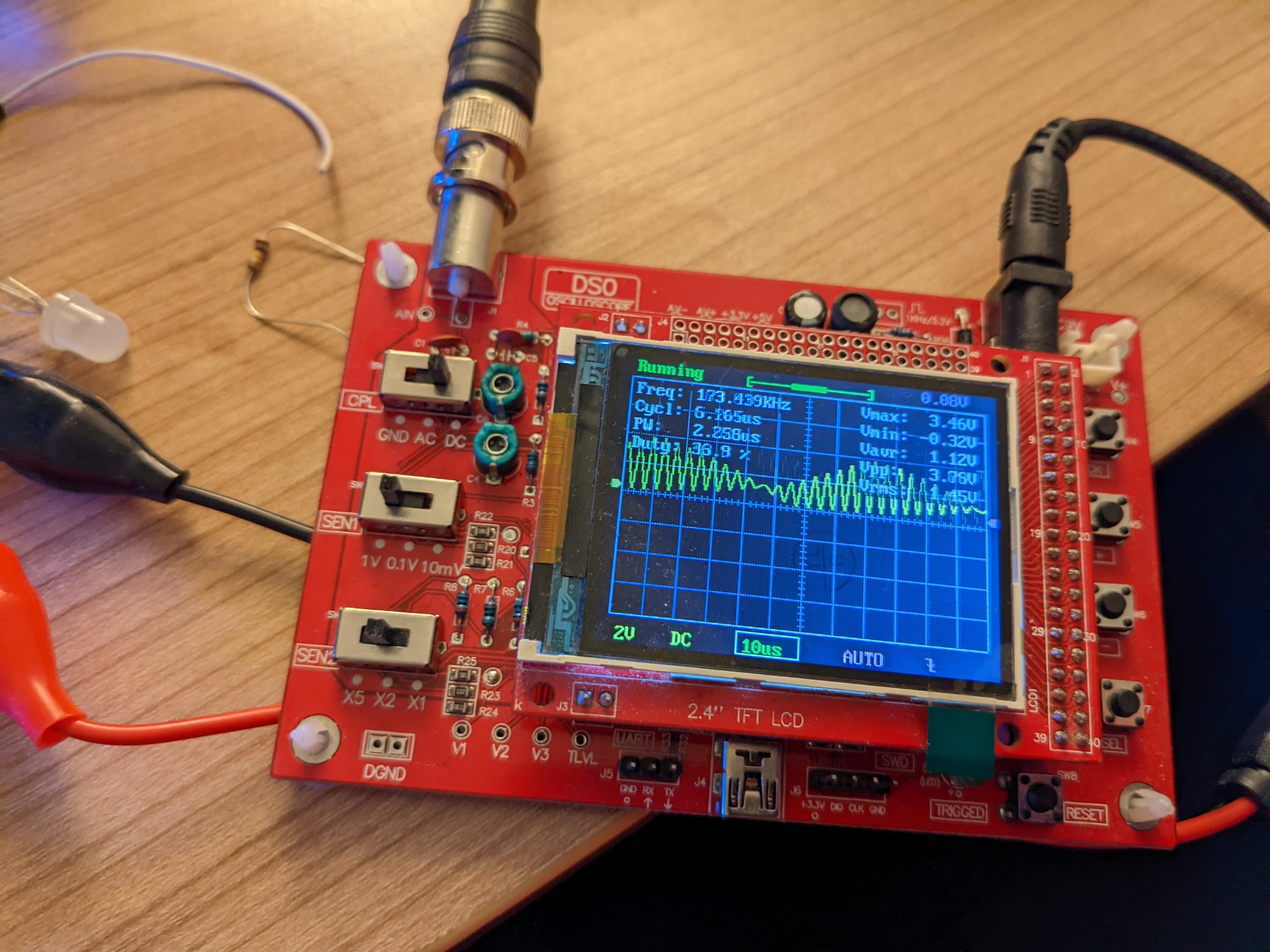
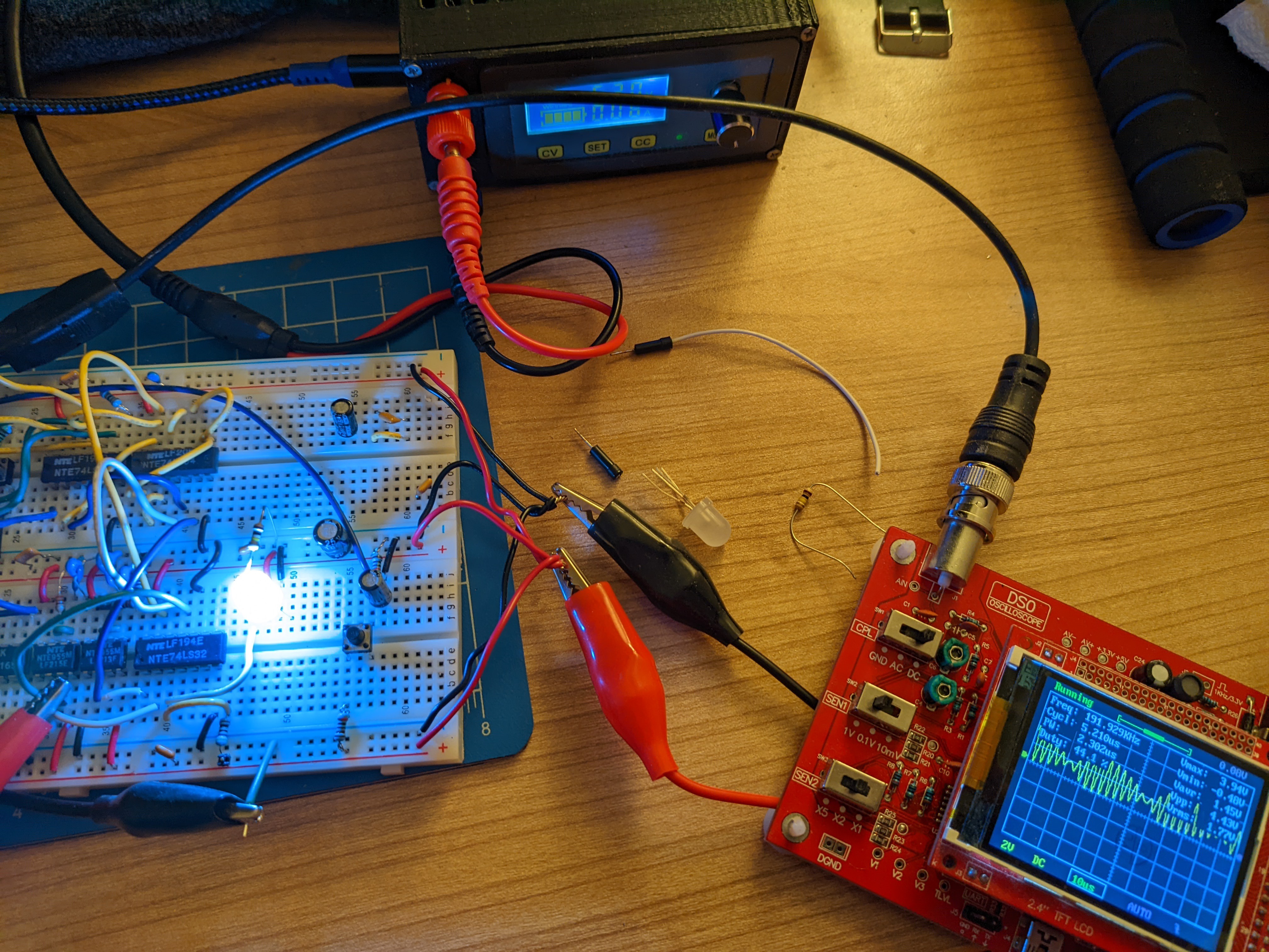
03/05/2022 at 20:30 • 0 commentsGood news! I got an oscilloscope! The core problem? The "750 KHz" clock was going at 230 KHz. Nice to finally know. No wonder nothing was going right.
-
The thing itself
01/17/2022 at 06:36 • 0 commentsWell, I missed the 555 contest cutoff. Darn. But here's my project anyway: A 555-based NeoPixel controller.
The Rube Goldberg 555 NeoPixel Controller
I wanted to create something marginally useful: a manual way to set the color for a single RGB NeoPixel. Maybe you could use it to test LEDs for duds. Maybe you could just use it. But I also decided that the 555 would be the only IC in the project. No logic gates, no crystals, no microcontroller.
You see, the meme here is that you could use a 555 in place of a microcontroller in many projects. So how can I create the most idiotic and complicated 555 device to do what any micro could do trivially?
This project rapidly exploded in size and complexity once I actually started to implement it. But I learned a lot about the 555 on the way.
My controller needed three parts besides the NeoPixel itself, and I wanted to add a fourth. They are:
- A 24-bit shift register, to hold an RGB triplet
- A clock source
- A clock/data to pulse encoder output stage
- An exotic memory, as a bonus
Like many, I was inspired by Peter Monta's Digital logic using 555 chips. I had recently played with assembling complex logic from NAND gates and thought I could build up with the 555 similarly. And in theory, sure! But in my naivete, I thought this could be done fairly trivially.
Let's go down the rabbit hole.
24-bit shift register made of 555s
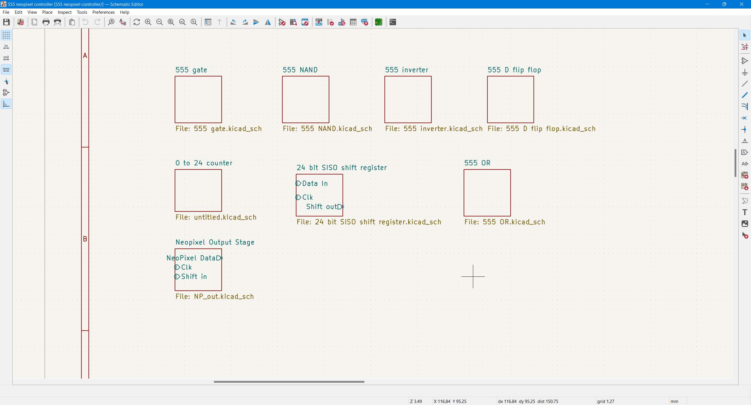
Early in the project, I knew I would be making use of KiCAD 6's nested schematics to simplify laying this out into something manageable. It makes it easy to wrangle clusters of 555s.
![]()
With hierarchical sheets, I could arrange and copy abstract blocks extremely easily in the schematic stage, speeding up the whole thing quite a bit.
![]()
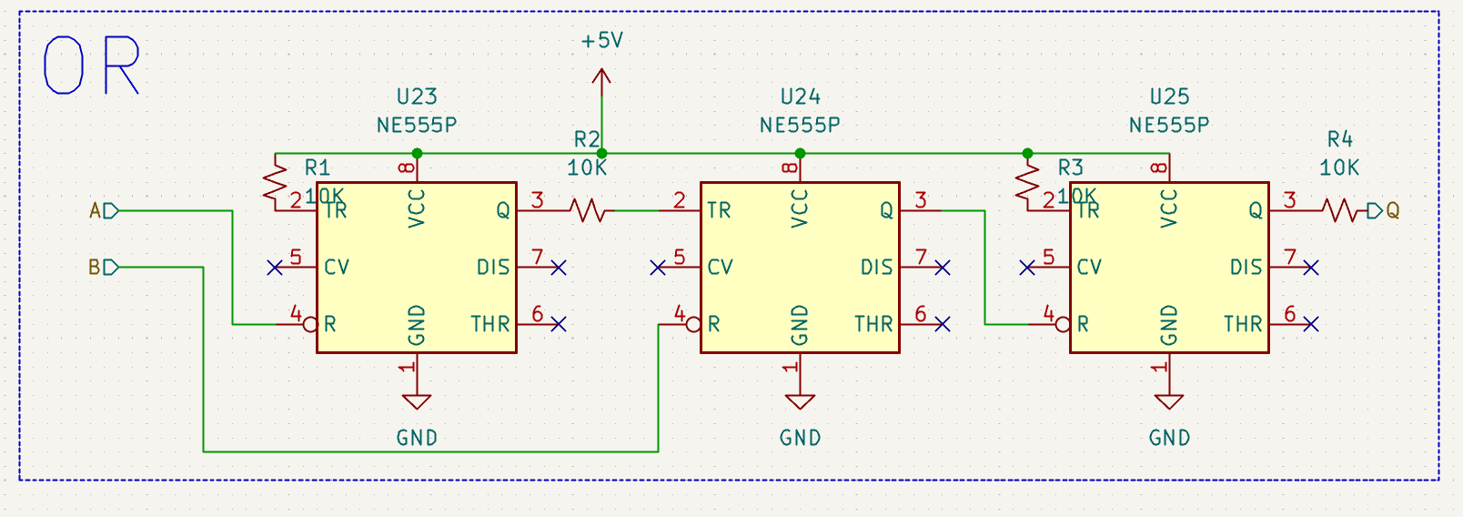
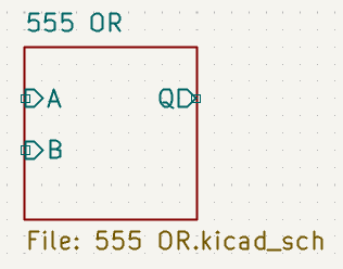
For example, this whole block (which doesn't even need the resistors, really) can be turned into this:
![]()
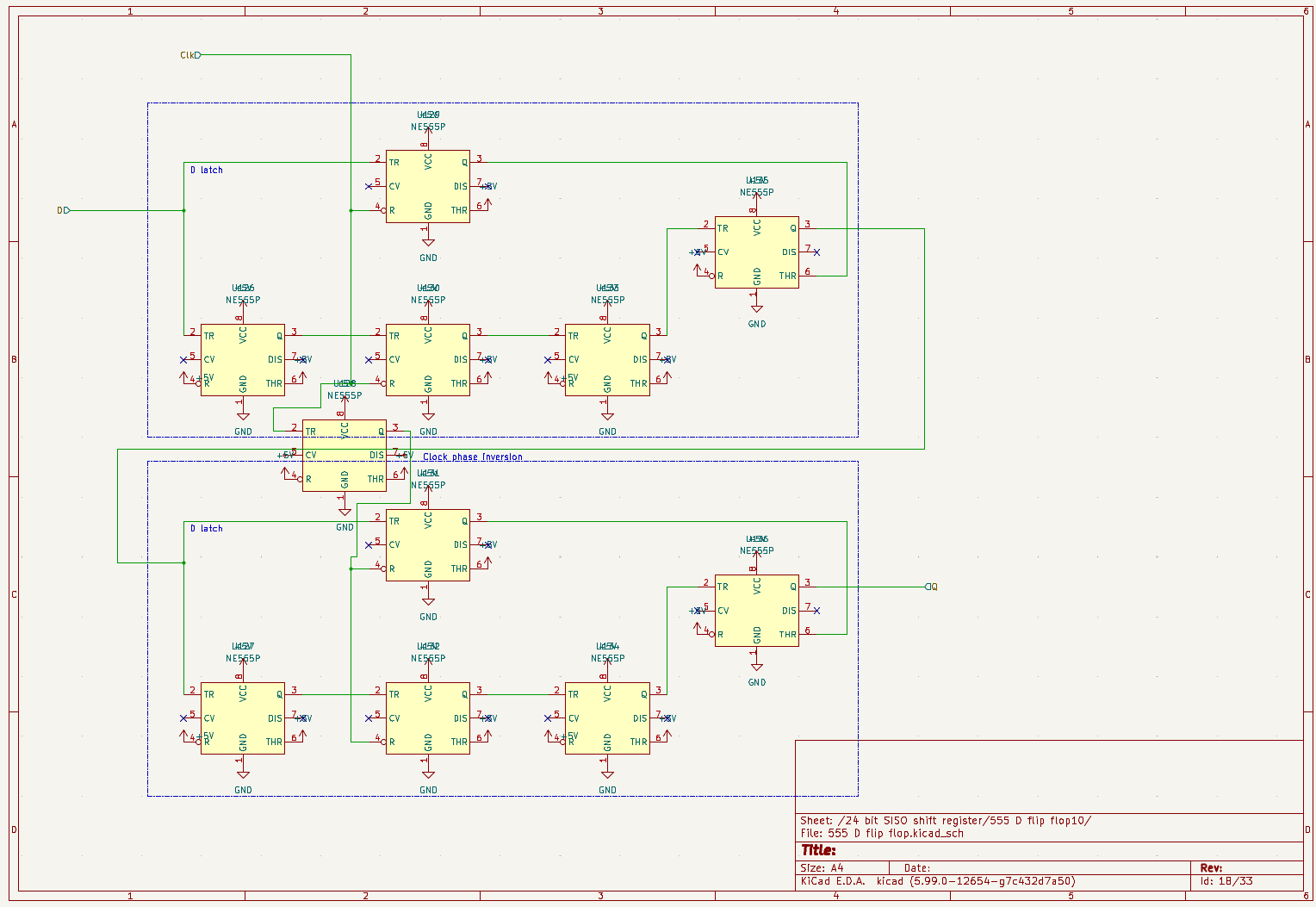
So I just implemented pmonta's D flip flop once... (I do not win the schematic artistry award)
![]()
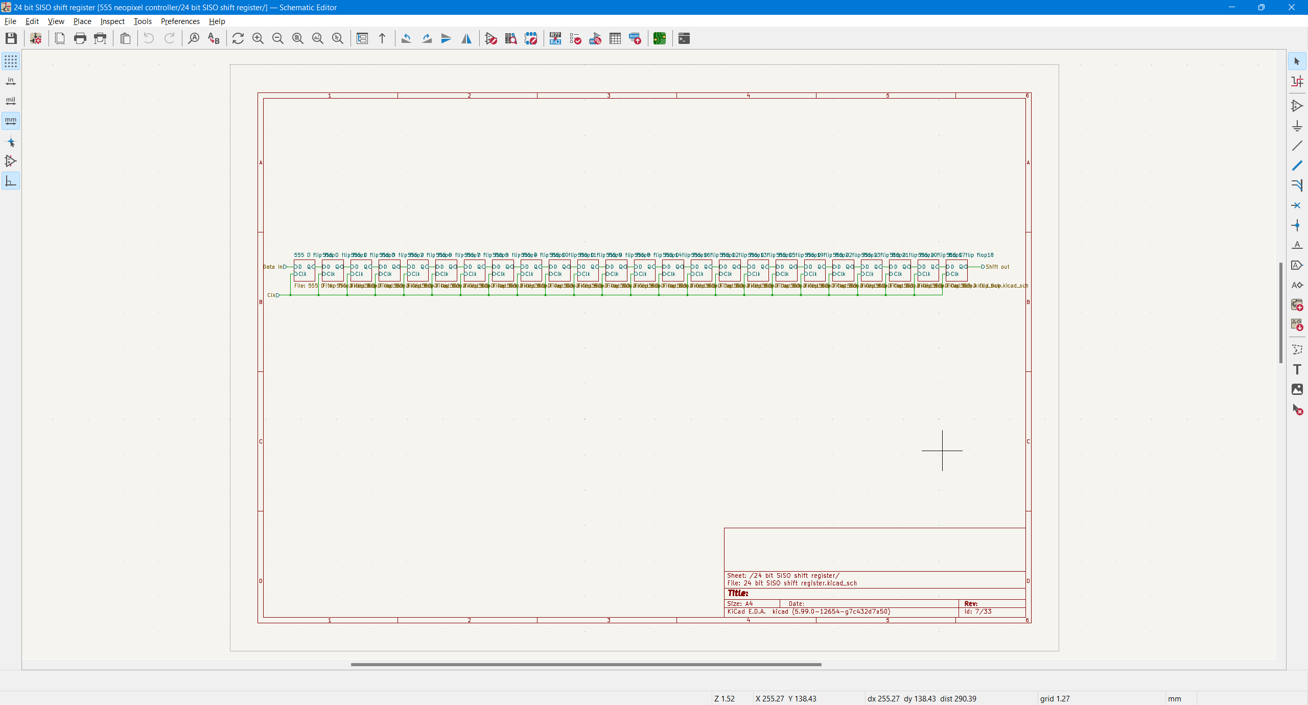
And then duplicated it 24 times.
![]()
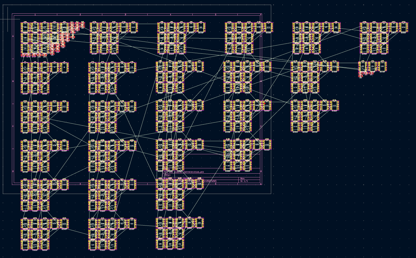
This is already very silly. You see the problem already, of course. That's 11 555s per flip flop, times 24 flip flops. That's 264 555s.
![]()
The PCB for this would be the size of an ATX motherboard if I actually laid it out.
And the memory density! DRAM has a component density of 1 transistor and 1 capacitor per bit. This is 11 555 timers per bit. Awful. I love it. But I can't build it out of 555s - it would cost hundreds of dollars. Maybe during my mid-life crisis, but not now.
--
One thing I did throughout this project was simulate the logic at the falstad.com Circuit Simulator Applet. This was critical, because pmonta's 555 digital logic writeup glossed over some details that I missed because I don't have his expertise. Specifically, I didn't understand 1) that there was 2-phase clocking and 2) why it was needed until I simulated the circuit and it behaved like a transparent latch.
My solution was (over)simple: I inserted a 555 NOT gate to invert the clock signal, giving a quasi-two-phase clocking to the two latches that made up the flip-flop.
One thing I did throughout this project was simulate the logic at the falstad.com Circuit Simulator Applet.
The Clock Source
This felt easy: I would do a slight variation on Ben Eater's clock module for his 8-bit breadboard CPU. This uses the 555 in its three basic modes - monostable, bistable, and astable - to select between a once-per-button-press clock pulse and a repeating clock source.
https://eater.net/8bit/clock I implemented this basically as is, with a handful of changes:
- The astable clock frequency was fixed at "somewhere around 800 KHz" - in design, about 750 KHz, in practice, maybe 720? We'll come back to that.
- The HLT line to stop the clock was omitted
- The 74LS04 was replaced with a 555 NOT gate.
- The Reset pin for the astable 555 was brought out to a debounced button so I could "fire" the NeoPixel data dramatically.
The pulse encoder - NeoPixel output stage
NeoPixels are surprisingly flexible in timing, especially the SK6812 variants I had wanted to use. For review, a NeoPixel data stream is a single line of self-clocked bits, where a short high time and long low time is "0" and a long high time with short low time is "1." But the actually critical timings are a bit more simple than the full specification:
- The data high time must be less than .30 microseconds to register as a zero.
- The data high time must be at least .55 microseconds to register as a one.
- The low time has to be about long enough for the cycle time per bit to come in at about 800 KHz.
- That's mostly it. SK6812s are a bit more rigid in terms of also timing the low times and overall, but in return give more flexibility for the high hold durations and overall clock rate.
For this section, I took inspiration from Ben Heck's SPI to NeoPixel decoder. This Ben used 74LS123 timers to fire off appropriately long 0-length and 1-length high pulses. Using some logic, the 0 pulse always fired and always showed up in the NeoPixel output, and the 1 pulse only fired to hold the output high longer if there was a data 1 bit on the data line. I omitted the chip select logic.
I thought it would be easy to adapt from one timer to another. So did another naive adaptation: When I built the prototype, I simplified: 0 fires every clock cycle, like Ben Heck's, rather than listening to the data logic at all. 1 only fires when there's a 1 on the data line.
But there's a big problem that I had to figure out, an important distinction: The 74LS123 has a single-shot mode, but the 555 is monostable. When the 74LS123's pulse is triggered with a button press, the pulse will always be the length defined by the RC network. If you hold the button, that doesn't re-trigger the pulse, and the output will be high only as long as the RC network specifies. The 555's monostable mode doesn't work like that.
When you fire a single pulse with a 555, the RC network will discharge in the time based on the datasheet. But if the button is still held down after the RC network discharges, the output will remain high. When your activation signal is longer than your desired output pulse, the output will be the length of your activation signal. My clock pulses were longer than the desired 0 bit pulse. In fact, they were long enough to be 1 pulses.
So when I first turned the prototype on, my NeoPixel turned white and stayed that way.
I ran into a lot of problems trying to debug this and while I made progress, I ultimately failed. More in the next section. If I revisit this project, I might simplify this section by adjusting the duty cycle of the astable 555 clock and then inverting it, so the default waveform of the clock is a NeoPixel 0 data bit. Then only one 555 and an OR gate can handle the 1 pulses.
Prototype
After seeing that I'd need hundreds of chips and an ATX sized board for the full project, I resigned myself to prototype, test, and debug just the clock generator and output encoder stages, supported with - ugh - conventional digital logic chips.
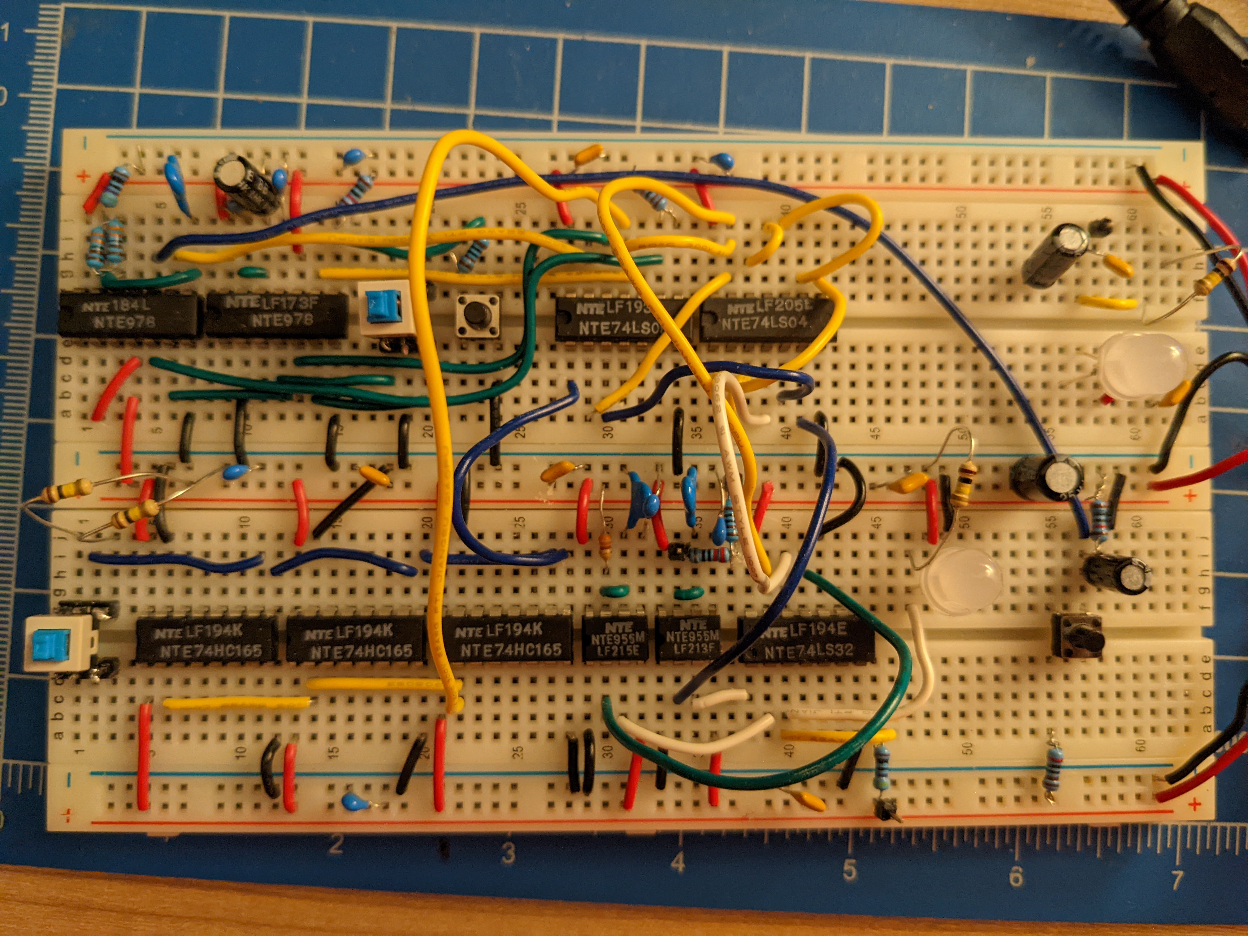
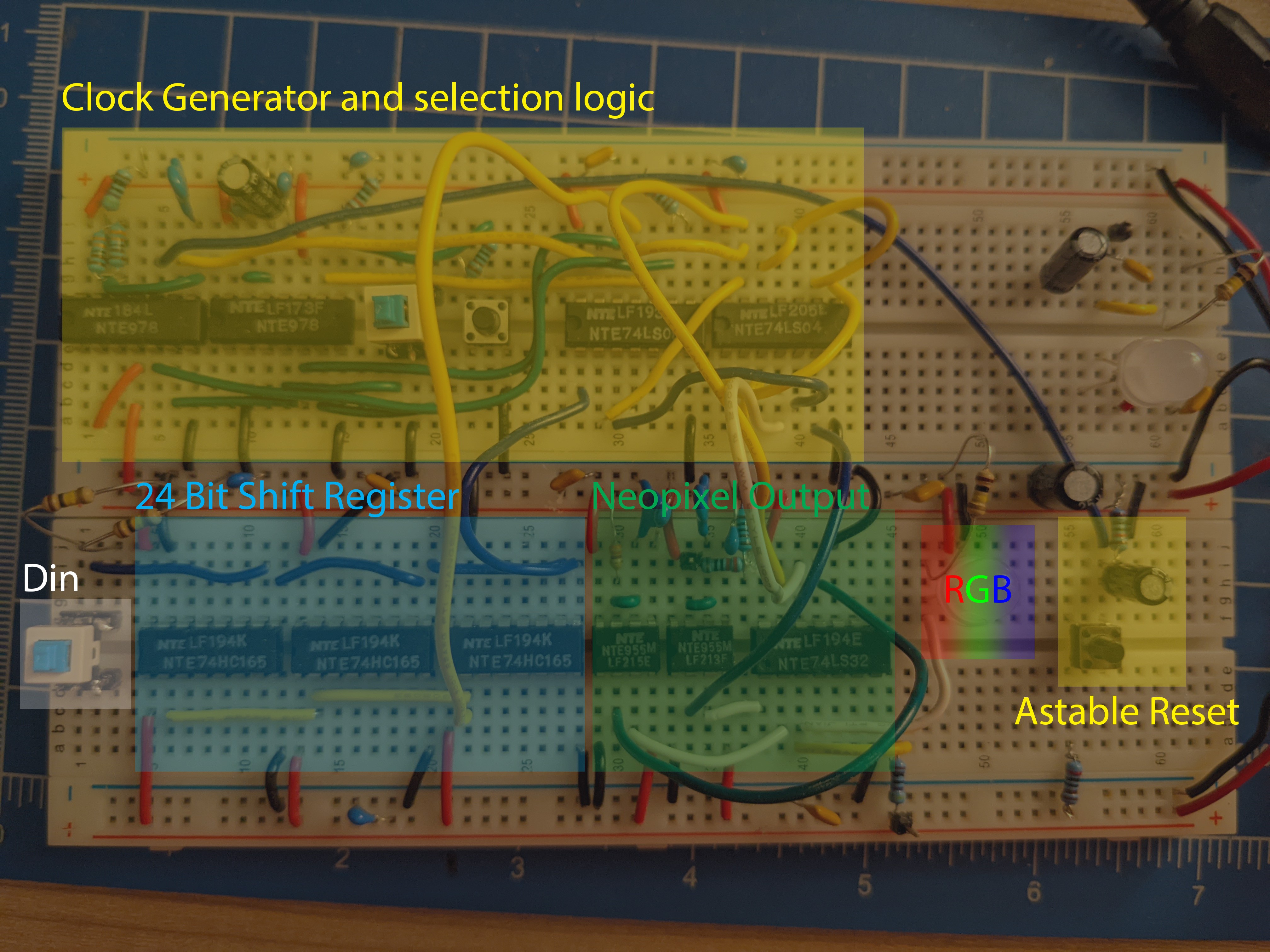
This is what it looks like at this moment:
![]()
![]()
I raided Micro Center and got to work. There were a few misc. hiccups as I went:
- I lost patience for proper-length, color-coded jumper wires during debugging
- My cheap through hole resistors had teeny tiny legs that couldn't make contact in the breadboard, so I had to twist up the leads double
- You need a pull-up resistor to mix 74LS and 74HC series chips
- General wiring errors
- Errant 60 Hz signals from mains until I added a load of bypass caps
- Logic level errors with accidental voltage dividers and illegal wiring two logic gate outputs to one spot
- Button leads didn't make good contact, making the astable reset button finicky and prone to phantoms
But for all that, the switching between clocked and single pulse works, the shift registers work. I can load an RGB triplet and see it come out of the output and mix properly with the clock to trigger the 1 pulse 555. And...
![]()
It turns on the LED! ... to random colors from noise. I was able to cut this down to only happening when powering up, but... Ugh. Look. This is my "oscilloscope":
![]()
It's one of those toys with 200 KHz analog bandwidth. It can't tell me how my clock or NeoPixel pulses look. I can tell when there's clock activity and that's about it. It was still a lot of information, though.
Remember the monostable, "all clock pulses are a NeoPixel 1" problem? After doing a little reading on gate propagation delay, I ran the clock through some unused inverters to shorten the pulse that triggered the 0-pulse 555, and mixed it with an OR gate so that the negative trigger pulse would be shorter than half the clock rate. Well first I tried one, but that didn't trigger the 555. Then I tried three. I ended up needing five dang inverters before the 0 pulse would trigger.
According to my "scope", the trigger never triggers, it's too brief. It just doesn't have the bandwidth. I can't debug the pulse length timing issues. I can see that the output goes wild, though, so it must be working.
![]()
So that's where I have to leave it. If I had won the 555 contest prize, I was gonna buy an oscilloscope. Welp!
--
This was longer than I thought. I'll share my potential 555 delay line memory shenanigans in another update. Until then, ciao!
The Rube Goldberg 555 Neopixel Controller
Manually control a single Neopixel with a toggle switch. 555 clock and data output, 555 shift register... 555 delay line memory??
 Paul
Paul