-
1Getting Started with FPGA Design
![]()
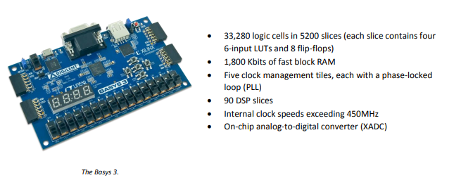
Instead of exact build instructions for the QIXOTE-1 Nine-Bit computer, I plan to put together some hints here for people who wish to get started designing their own hardware, and/or experimenting with FPGA design. For my project, I chose a (fairly old) development board called the BASYS 3. This is a board made by Digilent for educational purposes, and a great starting device. Commerical applications of this board are kind of limited, I would think most things you could do with this you could do better with an embedded processor system like Raspberry Pi. And if you really wanted state-of-the-art FPGA capability, you'd probably opt for a newer, hybrid board that pairs FPGA chips with a processor/SoC.
Buf if you just want to experiment with FPGA hardware, this is still a great board to start with. It has a bunch of stuff onboard that makes it easier to write starting designs that do something - like switches, buttons LEDs and programmable I/O ports similar to Raspberry Pi's GPIO.
-
2Learn a Hardware Description Language!
If you are new to chip design, then a starting point should be to learn a Hardware Description Language, such as SystemVerilog, Verilog, or VHDL. My recommendation is to learn Verilog first, it is the far more popular choice for HW designers and is actually the base layer below SystemVerilog, so if you learn Verilog you can apply what you learn to SystemVerilog later.
SystemVerilog is mainly focused on extending Verilog's non-synthesizable capabilities for test bench development, so a lot of what is added there can't be used for FPGA design, anyway (at least, with the Xilinx tools). And VHDL is in my opinion a more heavy-weight and some would say cumbersome language, popular in some quarters for designing IP blocks but probably not a great choice for beginners.
There are some decent Verilog courses online including this one from ASIC world. I can also recommend this book:
![]()
It's not super in-depth, but Verilog By Example covers the basics of Verilog and some issues that are specific to using it for FPGA design, so its not a bad one to have.
-
3Get Your Hardware Software Stack Together
You'll need special software in order to program an FPGA system, and your best bet is to use the software provided by the chip manufacturer. I have not worked with Altera chips (in recent memory anyway) so I can only speak to my current experiences working with a board featuring Xilinx FPGA chips.
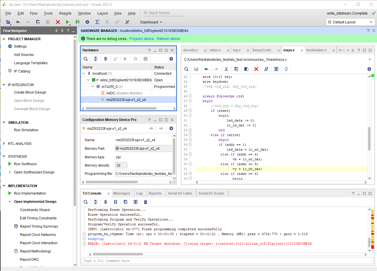
For this, I am using the Xilinx Vivado software package. The free tier "Standard Edition" of this package is more than capable of doing all the things you'll need to get your first design running on FPGA hardware.
![]()
I am using the Windows version of Vivado, 2021.2. If I was doing this for a living, I would probably to be honest look at switching to the Linux version, and possibly using the command-line interface to the tools with a separate editor, and some sort of Make-driven build process that can be managed and scaled.
For beginners though, the Vivado IDE provides some advantages, of dependency management, syntax/error checking, and tool flow integration that make it a pretty good starter choice. I find the Xilinx tools at least on Windows to be slow, and the IDE can be clunky at times. I also miss having revision system integration to git or similar in the tool, something I'm used to with other IDEs.
But those are not deal-breakers, and so far I've been able to create by nine-bit odd CPU just fine staying within this environment.
And it is one-stop-shopping. Vivado IDE will let you write code, simulate it, synthesize it, place/route, create bit streams for programming the FPGA live, or for configuring onboard memory. The simulator and accompanying waveform viewer are basic but get the job done. If you have a better / bigger simulator like Cadence XCelium, you can integrate it, but it is kind of overkill for the hobbyist.
If you are building yourself a CPU, or embedding a prebuilt one in your FPGA, you will eventually have to think about the software tool chain for programming it. Xilinx has a MicroBlaze CPU that can be added to your FPGA and a comprehensive tool chain to work with it. But if you wanted to do some FPGA/embedded CPU combo and were not crazy like me and designing one of your own, you would probably be better off getting a combo board that has an ARM processor with side FPGA and work with that.
I will talk some about my software toolchain in my newsletter, the Mad Ned Memo, later. Because I chose to go a totally nonstandard 9-bit route, things like ELF format, and standard embedded software tools are really not on the table for me, so I can't really provide a lot of useful info about the existing ones compatible with Vivado/Xilinx.
-
4Setting Up your FPGA Board
Once you get your BASYS 3 FPGA board and a copy of Vivado, you are ready to start trying to get your first FPGA hardware design running. I recommend starting with something extremely simple, like lighting an LED. This is what I've called before the "Hello World" of hardware design.
To do it, you really will need two things. A verilog file to represent your design, and a configuration file that tells Vivado what pins of your board connect to what signals in your verilog code (what Xilinx calls a .xdc file - sample in the files section) You should copy in some existing xdc file appropriate to your board for the config and edit it as necessary. Any pins you are not using should be commented out or it could lead to implementation errors when you try to route your design.
You should have an entry there though for the LED you want to turn on, example for BASYS 3 that corresponds to the rightmost LED light on the board (pin U16):
set_property PACKAGE_PIN U16 [get_ports {LED[0]}]
set_property IOSTANDARD LVCMOS33 [get_ports {LED[0]}]
This creates a signal called LED which is attached to U16.
There are a few other setup details you might need:
- in Project Settings > General, you need to select your board as the device (Eg BASYS 3)
- Also in General, add a top module name (eg 'top') that matches the verilog file you add - eg: top.v
In your top.v file, you would add in an output port that matches the name of the LED from the config file:
module top( output LED);

    assign LED = 1'b0; // let there be (green) light!

endmodule
From here, you follow this flow in Vivado:
1. Synthesize your design
2. Implement your design
3. Generate Bitstream
4. Download bitstream to your board
(on these in the steps that will follow)
Holy Nonads! A Nine-Bit CPU!
A journey to discover what it's like to build your own processor.
 Mad Ned


Discussions
Become a Hackaday.io Member
Create an account to leave a comment. Already have an account? Log In.