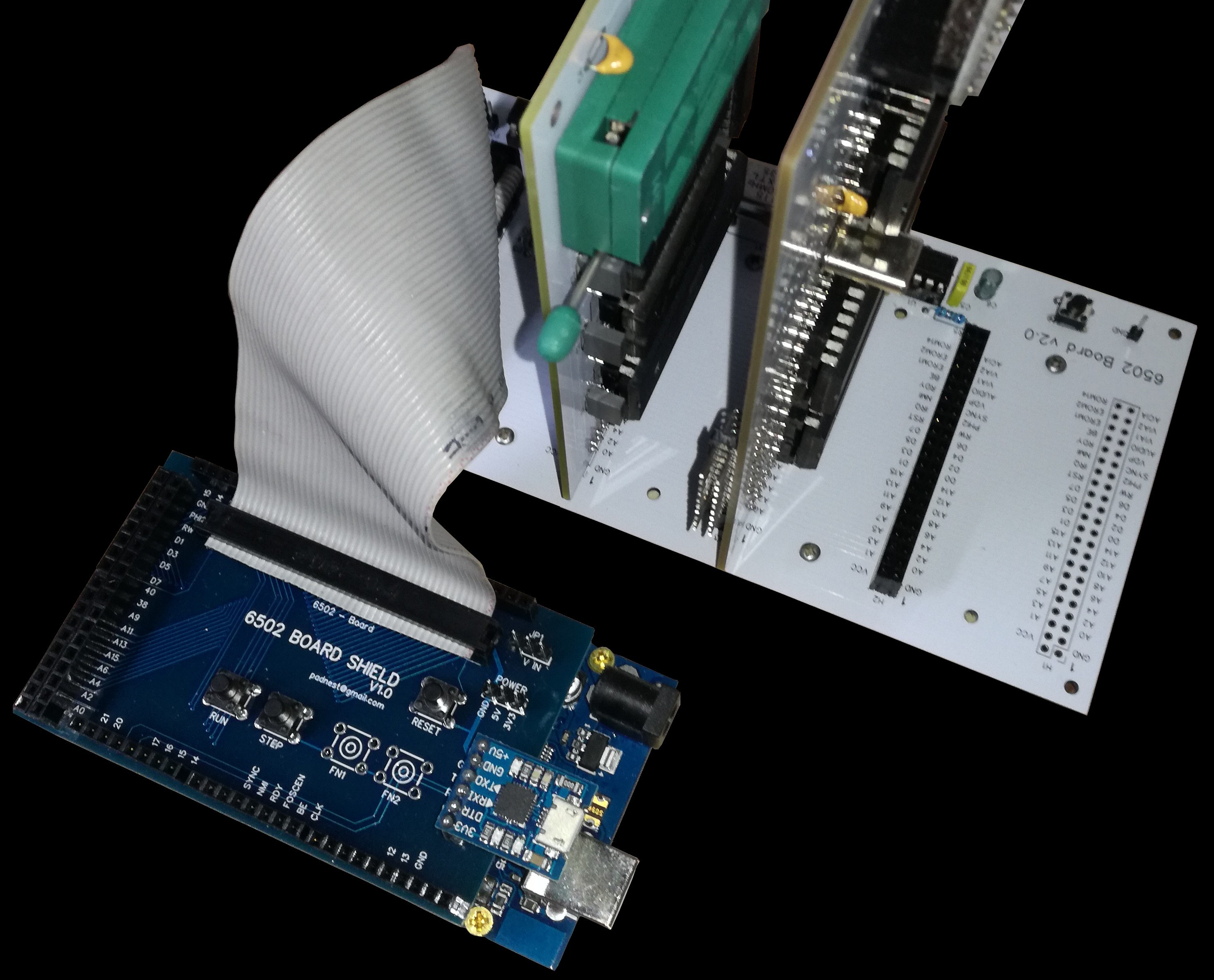
I designed this shield to easily connect the Arduino Mega to the MRC6502 system.

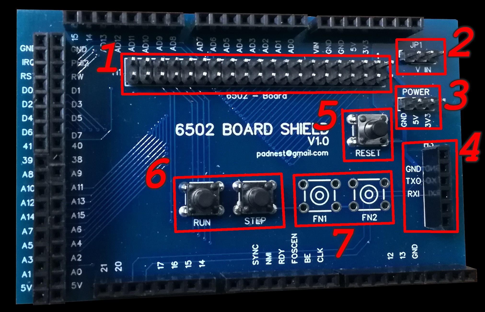
It has pass through headers for bus signals, control buttons and a socket for an additional usb serial module.

- 40 pin male header to connect the MRC6502 mother board (1)
- Arduino power supply selector (2)
- power rails header (3)
- CP-2102 usb serial module socket (4)
- reset button (5)
- CPU execution control buttons (6)
- extra function buttons (7)
Connections
Arduino can access to the system bus in order to control the CPU execution, read and write memory and devices registers, generate slow system clock or enable fast board clock generator.

Arduino used ports are:
- PORT L (bidirectional) ==> bus data lines
- PORT A (bidirectional) ==> low bus address lines
- PORT C (bidirectional) ==> high bus address lines
- PORT B:
- bit 0 (output) ==> bus IRQ line
- bit 1 (input) ==> bus PHI2 line
- bit 2 (output) ==> bus RST line
- bit 3 (output) ==> bus R/W control line
- PORT E:
- bit 3 (output) ==> mother board A-FOSCEN control line
- bit 4 (input) ==> bus SYNCH line
- bit 5 (output) ==> bus NMI line
- PORT H:
- bit 3 (output) ==> bus BE line
- bit 4 (output) ==> mother board A-CLK line
- PORT G:
- bit 5 (output) ==> bus RDY line
Schematics: here
See you next step.
Ciao!
 padnest
Discussions
Become a Hackaday.io Member
Create an account to leave a comment. Already have an account? Log In.