 George A.M.
-
1Building the Servo Controller
Before we can start using the infrared controller, we need to make the code to control the servos using buttons. This code will be used later and modified to be used with the infrared.
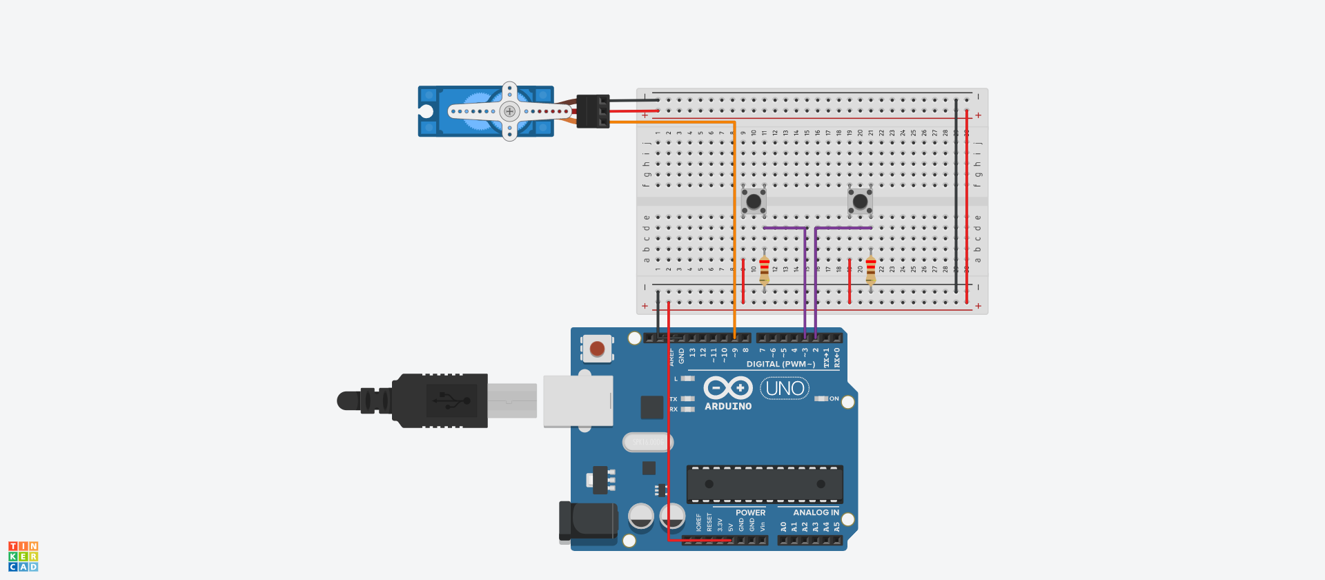
Use the following diagram to build the servo controller. This design mimics the controls you will have on the infrared controller later.
Parts required include: 1 x Servo Motor, 1 x Arduino UNO R3 Board, 2 x Pushbuttons, 2 x 220 Ω resistors, and connector cables.
![]()
The following code is what I used when assembling the controller.
#include <Servo.h> //Include the servo library
Servo myservo; //Make an integer for the Servo
int val; //Make a value for the rotation
const int buttonPin = 2; //Set a state and integer for the left button
int buttonState = 0;
const int button2Pin = 3; //Set a state and integer for the right button
int button2State = 0;void setup()
{
myservo.attach(9); //Attach the servo to pin 9
pinMode(buttonPin, INPUT); //Set both button 1 and 2 as inputs
pinMode(button2Pin, INPUT);
myservo.write(90); //Set the rotation value to 90*
} // this will be considered the "neutral" statevoid loop()
{
buttonState = digitalRead(buttonPin); //Assign the states of the buttons
button2State = digitalRead(button2Pin); // to HIGH or LOW respective to their state
if (buttonState == HIGH){ //If the "Left rotate button" is pushed
val = 150; // set the rotation value to 150
} // (max 180* modify to your range)
else if (button2State == HIGH){ //If the "Right rotate button" is pushed
val = 30; // set the rotation value to 30
} // (max 0* modify to your range)
else { //If neither or pushed reset to the neutral (90*)
val = 90;
}
myservo.write(val); //Have the servos rotation match
delay(15); // the rotation value
}Copy this code into your program and test it. When you push each button the servo should rotate roughly 45* .
I have also included the circuit diagram for this step. You can find it under files.
-
2Building the full turret circuit
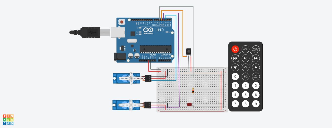
Next you'll be putting the full circuit together. This will include
2 x Servo Motor, 1 x Arduino UNO R3 Board, 1 x 1 kΩ resistors, an infrared receiver + remote, and connector cables.
Use the following diagram to complete the Circuitry
![]()
Then you'll want to include the following code:
#include <IRremote.h>
#include <Servo.h>const byte Reciever = 4; //Make a constant for the IR Receiver
const byte LASER = 5; //Make a constant for the LED (representing the laser)
Servo TILT; //Connect a servo for the angle Tilt
Servo AIM; //Connect a second servo for the rotation Aim
int val; //Make 2 Variables, these are used to set the angle
int val2; // of the servosIRrecv irrecv(Reciever); //Connect the previously constant of the IR Receiver
decode_results results; // to the IR remote and determine which button is pressedvoid setup()
{
Serial.begin(9600); //Start the serial monitor
pinMode(LASER, OUTPUT); //Set the LED as an output
TILT.attach(3); //Attach the servos to their pins
AIM.attach(2);
val = 0;
val2 = 0;
irrecv.enableIRIn(); //Enable the receiver to "receive" data
}void loop()
{
TILT.write(val); //Check servo values and
AIM.write(val2); // angle the servos to match
if (irrecv.decode(&results)) //If the reciver collects data
{
Serial.print("irCode: "); //print”irCode: ”
Serial.print(results.value, HEX); //print the value in hexdecimal
Serial.print(", bits: "); //print” , bits: ”
Serial.println(results.bits); //print the bits
irrecv.resume(); //Wait for the next input + data
}
if (results.value == 0xFD00FF){ //Power button
digitalWrite(LASER,HIGH); //Turn on the laser
val = 90; //Set servo values
val2 = 90;
}
if (results.value == 0xFD40BF) //Stop function button
{
digitalWrite(LASER,LOW); //Turn everything off
val = 1;
val2 = 1;
}
if (results.value == 0xFD28D7){ // #2 Button
val = 150;
}
if (results.value == 0xFD6897){ // #8 Button
val = 30;
}
if (results.value == 0xFD8877){ // #6 Button
val2 = 150;
}
if (results.value == 0xFD9867){ // #4 Button
val2 = 30;
}
if (results.value == 0xFDA857){ // #5 Button
val = 90;
val2 = 90;
}
}Copy this code and run it. If done correctly the buttons should either turn the led on / off, and rotate the servos. The values can be changed to your need.
The circuit diagram has also been included. Unfortunately I have not made a physical build of this project yet, but stay tuned. The future is coming.
Discussions
Become a Hackaday.io Member
Create an account to leave a comment. Already have an account? Log In.