 robotistan
-
1Step 1 : Getting Required Hardware
![]()
There are a few phases to completing the project. First, we'll construct the platform that will allow the system to rotate on its axis. After that, we'll look at electrical component layout and connections. Finally, we'll publish a piece of embedded software that was created just for the solar tracker project.
Do not forget to visit Robotistan's Blog for more : Solar Tracking System Using Arduino
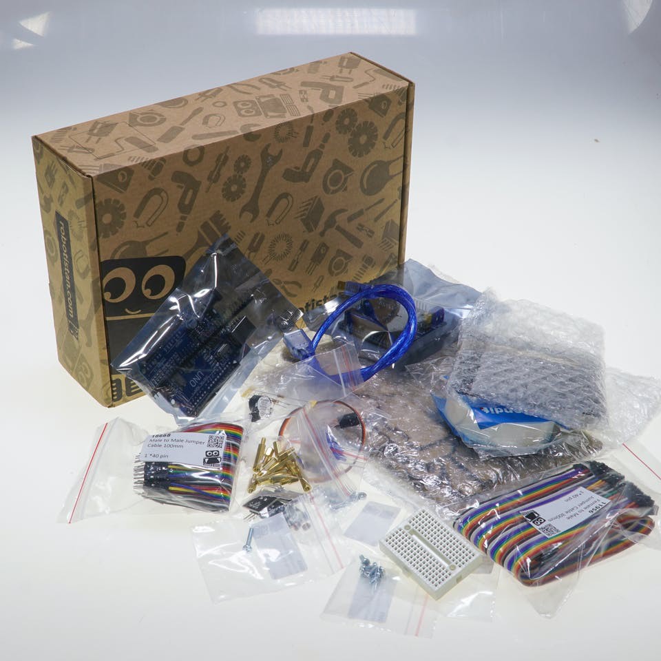
You'll need all of the required components to create a solar tracker system, including a solar panel, a microcontroller, and servo motors. You may purchase a "Solar Project Kit" that has all of the required components in one convenient box. The project will be straightforward to implement after that.
You can get the Solar Tracker Kit from : DIY Educational Sun Tracker Kit
-
2Step 2: Check Numbers of Parts
![]()
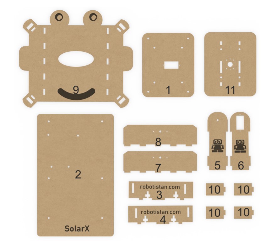
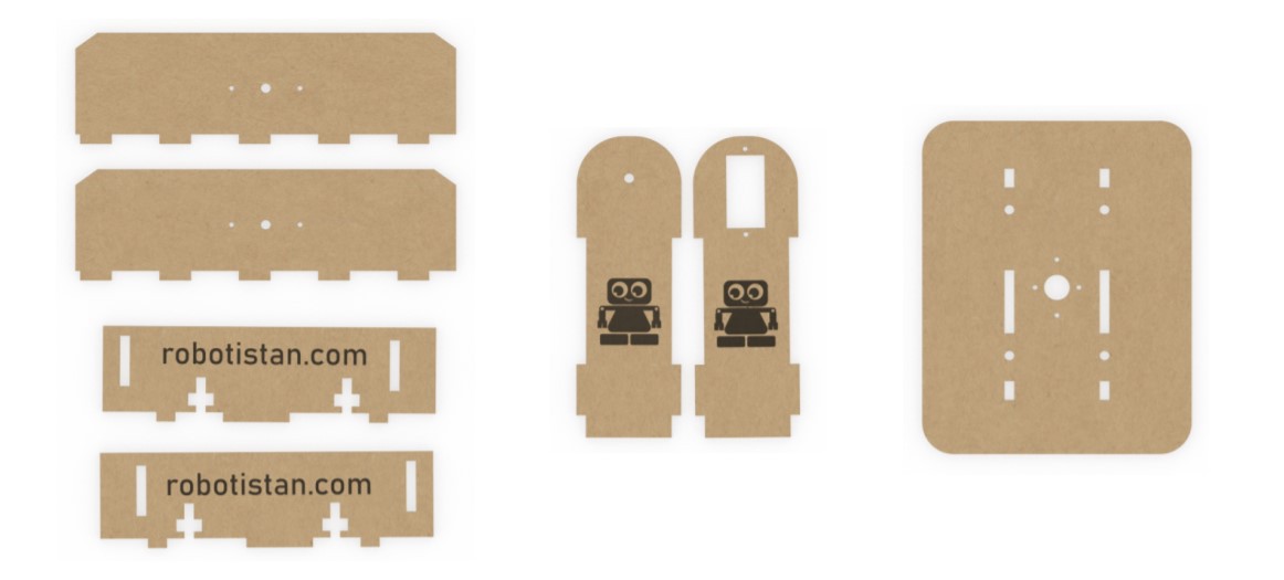
In this diagram, the numbers of the wooden components are shown. In the next steps, we'll go through which piece to utilize and how to use it.
-
3Step 3: Body Assembly
![]()
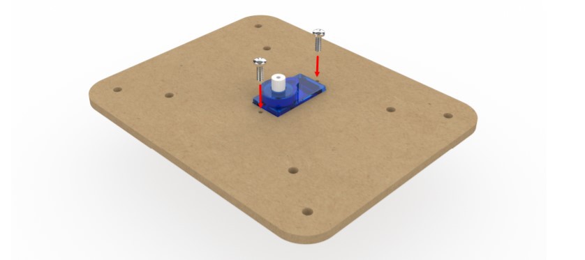
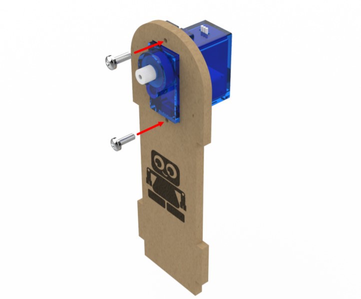
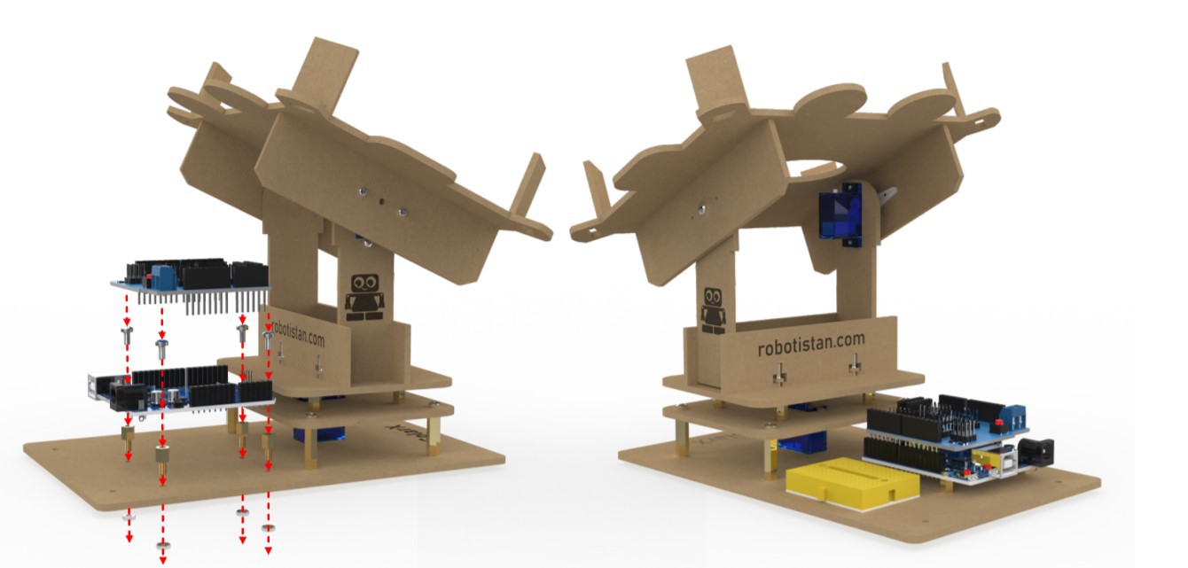
First of all, we will install the servo motor in the number 1 part. Mount it using the two long screws that come out of the servo motor package.
![]()
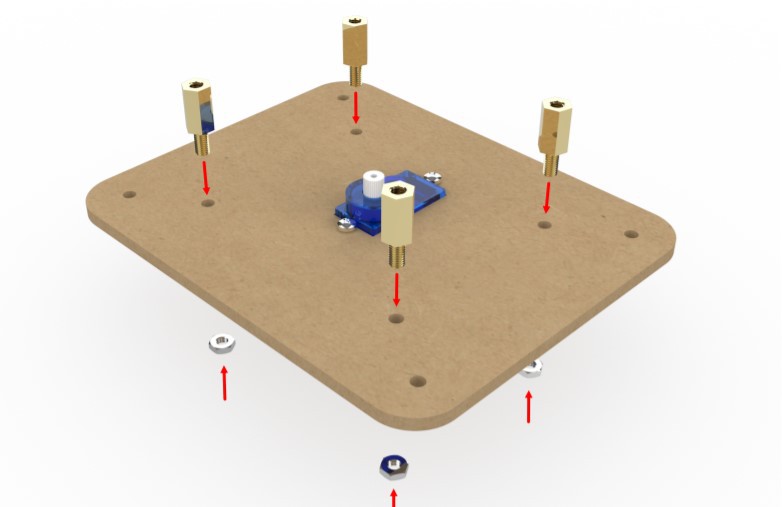
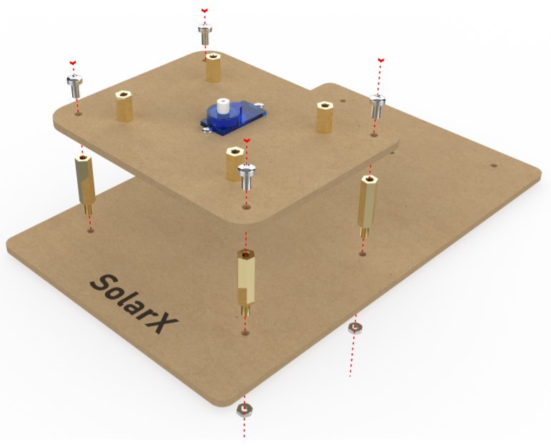
Mount the servo motor with 4 10 MM spacers and 4 nuts to the part number 1 where we mount it. These spacers will help the upper body to rotate more stable.
![]()
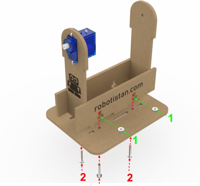
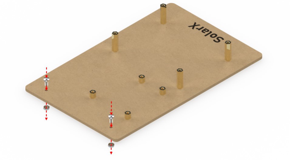
To raise the part number 1 from the bottom plate, mount 4 20 MM spacers using 4 nuts.
The next step is to put component number 1 on top of part number 2. Using 4 6 MM bolts, attach the part number 1 to the 20 mm spacers on the part number 2. The construction of the solarx lower body will be completed after this phase.
-
4Step 4: Upper Body Assembly
![]()
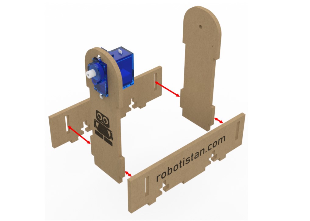
There are two portions to the upper body. The first portion is the one that adjusts the solar panel left and right. The component that rises and lowers the solar panel may be thought of as the second portion. I'll teach you how to put the first part together in this step.
The construction of the first section requires the pieces numbered 3, 4, 5, 6, and 4 10MM bolts, respectively.
![]()
![]()
![]()
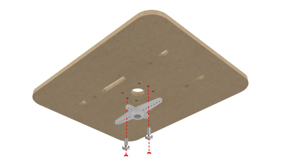
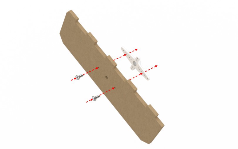
Fix the part number 5, with the gear part of the servo motor upwards, with the screws that come next.
![]()
![]()
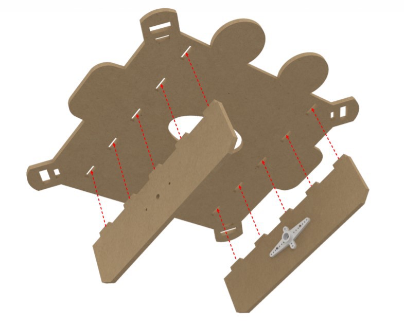
To begin, we must join the pieces 3, 5, and 6 as depicted in the figure. It's typical for the pieces to have a difficult time fitting together. You have the ability to exert some force. Then, using 10 MM bolts and nuts, join the finished pieces to part number 4.
After the assembly of the first part is finished. Mount the servo head that comes out of the servo motor package to the part number 4 with the M2 bolt in the set as shown in the picture.
![]()
You can proceed to the second half of the top part's assembly if you've completed all of the preceding steps. Use numbers 7, 8, 9, and 10 to assemble the second segment. An M2 bolt from the set is required to screw the numbered parts, servo cap, and servo cap together.
![]()
In the first step, fix the pieces 7 and 8 by passing them through the holes on the unshaped side of the piece 9. The pieces can cross each other a little hard, so don’t worry.
![]()
After you've completed parts 7 and 8, you're ready to go on to part 9. As illustrated in the figure, attach the servo head to component number 8 using the M2 bolt included in the package.
![]()
As indicated in the figure, attach the 15 mm bolt that allows the part number 9 to move up and down to the part number 7 with one nut. The assembly of the second half will be completed after this step.
![]()
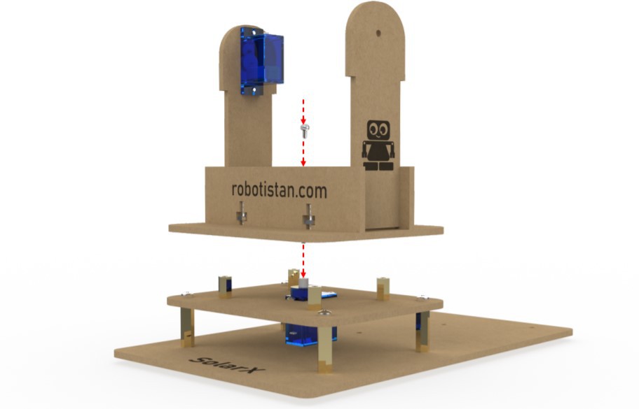
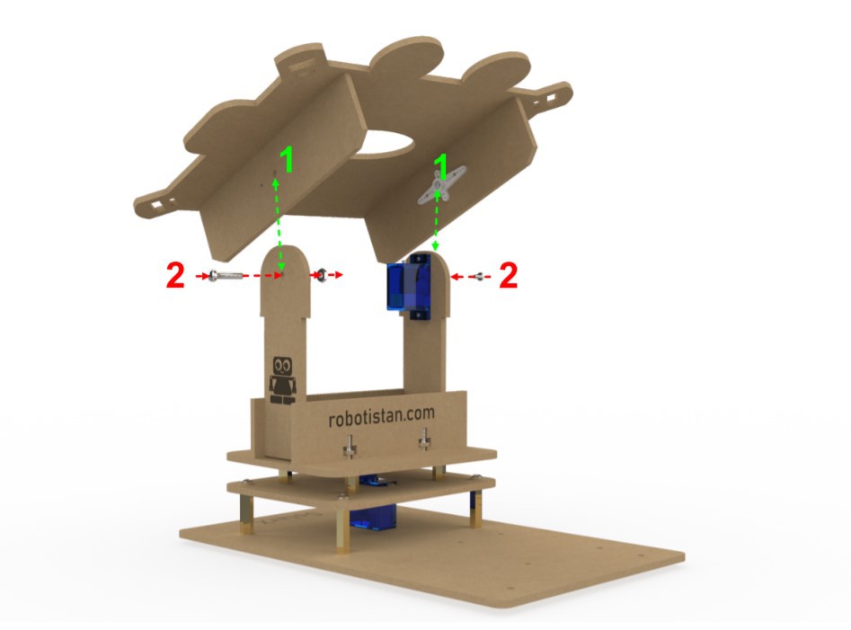
In this step, the first and second sections will be joined. As illustrated in the figure, we feed the 15 mm bolt we fastened to part number 7 through the hole on part number 6 and secure it with a nut. Please don't tighten this nut too much.
Because if you squeeze it too hard, it won't be able to move up and down easily. Then we use the small screw that comes with the kit to attach the servo head in part 8 to the servo motor in number 5.
![]()
Fix 2 6 mm bolts with 2 nuts to component number 2 as the final phase of the mechanical installation, as indicated in the photo. We do this because solarx does not wobble when it is placed on level surfaces. The mechanical parts assembly will be completed after this phase.
![]()
![]()
![]()
-
5Step 5: Electronics Connection
![]()
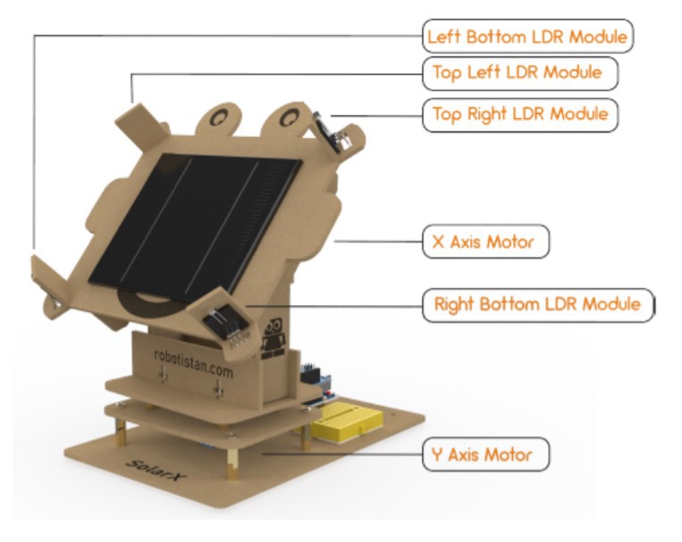
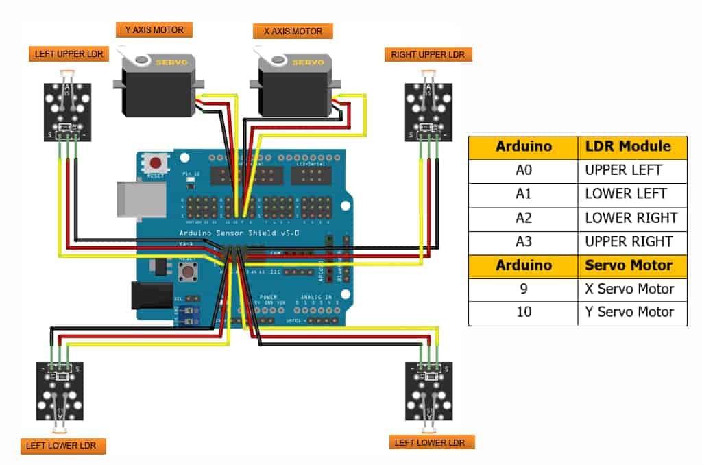
You may connect LDR and servo motors to Arduino Shield using the schematic and connection table below. As you connect the LDR modules, pay attention to the instructions. Otherwise, your solar panel will rotate in the other direction.
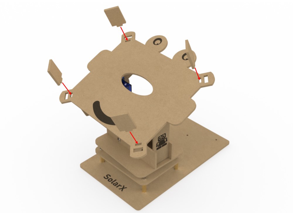
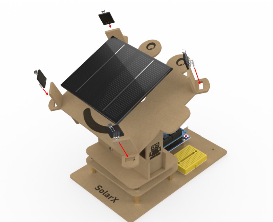
With the guidance of the graphic below, adhere the LDR modules to the 10 numbered pieces using the double-sided tape supplied in the package.
![]()
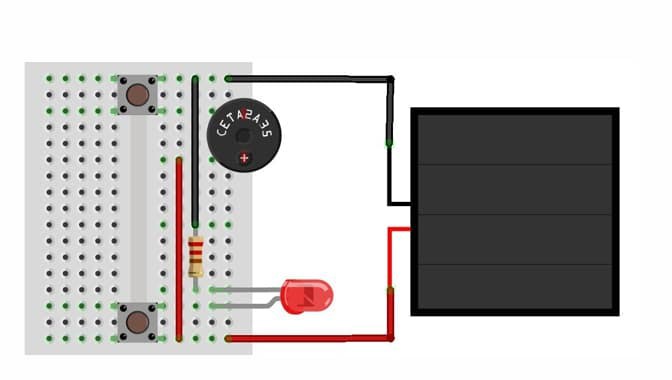
You may start utilizing the energy from the solar panel to power items after you've connected the LDR and servo motors. It's up to you to find out how to make the most of the solar panel's electricity. You'll need it whether you're planning to store it, charge the battery, or power your Arduino. As an example, I created a circuit design utilizing the buzzer and LED that included with the kit. You may use the electricity generated by the solar panel by following the circuit schematic below.
![]()
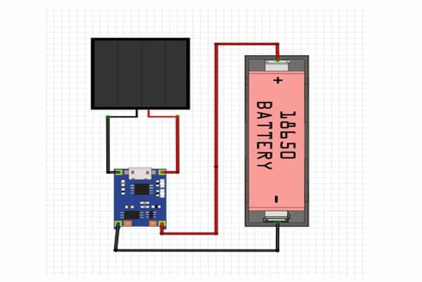
We've included another project idea as an example in case you want to do more with the energy you get from the sun. You'll need a battery charging circuit to finish this project. Because the solar panel's energy output is not always constant. To charge the battery, you'll need a steady supply of energy. The battery compartment will also be required for simple battery removal and installation. The items I'm referring about aren't included in the package. The set's content has been designed in such a manner that the buzzer and LED can be activated.
-
6Step 6: Arduino Codes
![]()
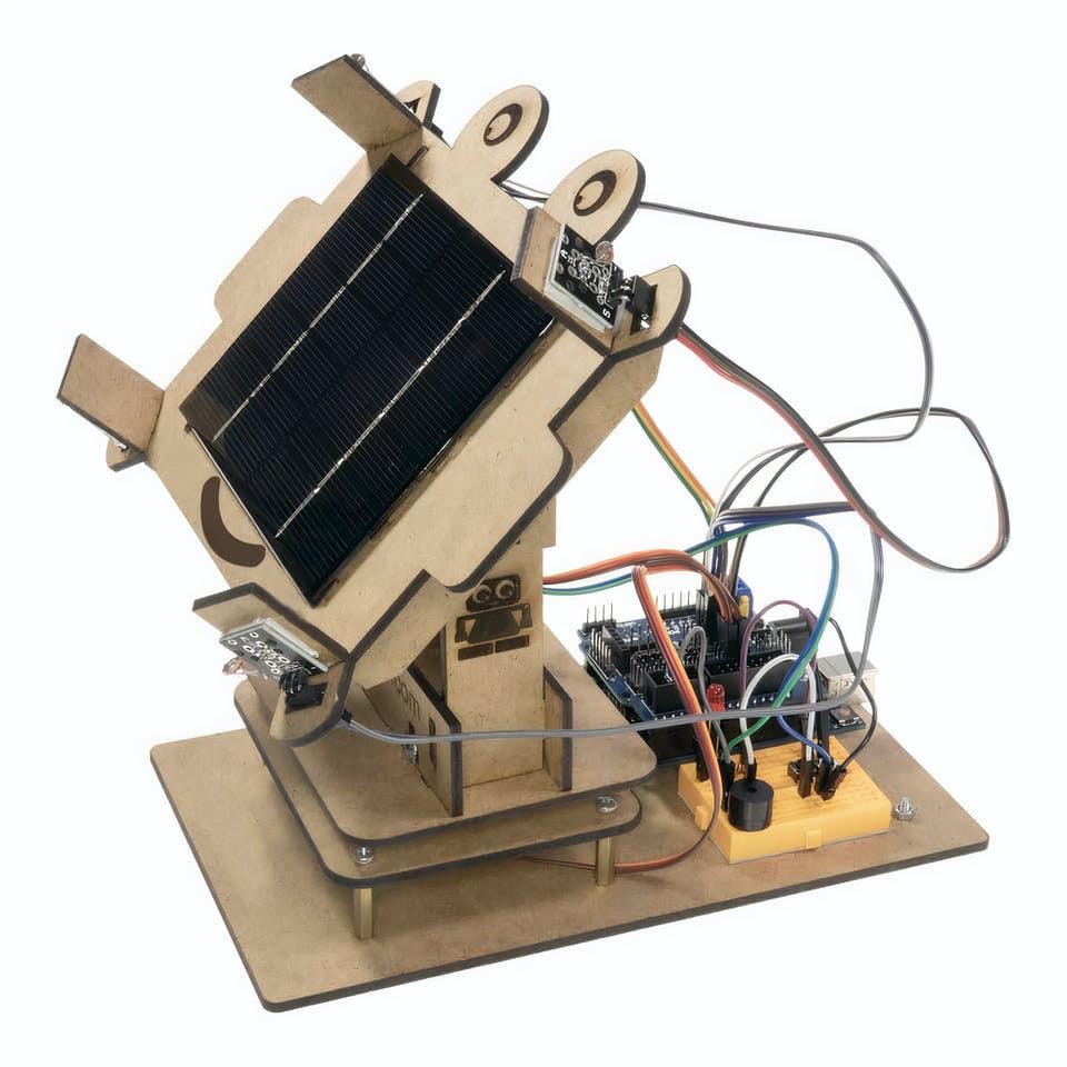
The platform's construction is complete. However, our project still need code to function. This code should be uploaded to Arduino:
#include <Servo.h>
//defining Servoss


#define TOLERANCE       10
#define STEP_DELAY      7
Servo servohori;
int servoh = 0;
int servohLimitHigh = 160;
int servohLimitLow = 20;


Servo servoverti;
int servov = 0;
int servovLimitHigh = 160;
int servovLimitLow = 20;
//Assigning LDRs
int ldrtopl = A0; //top left LDR green
int ldrtopr = A3; //top right LDR yellow
int ldrbotl = A1; // bottom left LDR blue
int ldrbotr = A2; // bottom right LDR orange


void setup ()
{
  servohori.attach(10);
  servohori.write(45);
  servoverti.attach(9);
  servoverti.write(45);
  Serial.begin(9600);
  delay(500);
}


void loop()
{
  servoh = servohori.read();
  servov = servoverti.read();
  //capturing analog values of each LDR
  int topl = analogRead(ldrtopl);
  int topr = analogRead(ldrtopr);
  int botl = analogRead(ldrbotl);
  int botr = analogRead(ldrbotr);
  // calculating average
  int avgtop = (topl + topr) / 2; //average of top LDRs
  int avgbot = (botl + botr) / 2; //average of bottom LDRs
  int avgleft = (topl + botl) / 2; //average of left LDRs
  int avgright = (topr + botr) / 2; //average of right LDRs
  Serial.println(avgtop);


  if (TOLERANCE < avgbot - avgtop)
  {
    servoverti.write(servov + 1);
    if (servov > servovLimitHigh)
    {
      servov = servovLimitHigh;
    }
    delay(STEP_DELAY);
  }


  else if (TOLERANCE < avgtop - avgbot)
  {
    servoverti.write(servov - 1);
    if (servov < servovLimitLow)
    {
      servov = servovLimitLow;
    }
    delay(STEP_DELAY);
  }


  else
  {
    servoverti.write(servov);
  }


  if (avgleft - avgright > TOLERANCE)
  {
    servohori.write(servoh + 1);


    if (servoh > servohLimitHigh)
    {
      servoh = servohLimitHigh;
    }
    delay(STEP_DELAY);
  }


  else if (avgright - avgleft > TOLERANCE)
  {
    servohori.write(servoh - 1);


    if (servoh < servohLimitLow)
    {
      servoh = servohLimitLow;
    }
    delay(STEP_DELAY);
  }


  else
  {
    servohori.write(servoh);
  }
  delay(STEP_DELAY);
}
You have successfully completed the Solar Tracker Project!
DIY Solar Panel Tracker with Arduino
In this article, we'll use Arduino to build our own solar system in the home conditions.
Discussions
Become a Hackaday.io Member
Create an account to leave a comment. Already have an account? Log In.