 doctek
-
1Step 1 Hardware Hook-Up
Since our object is to drive an actual stepper motor with an Arduino, we'll need some hardware. Before we jump into the software, we need to connect our motor and driver to the Arduino. I'll also briefly discuss the driver and motor types and their strengths and weaknesses. Here are the most common motor types and the drivers used with them. You can find much more detail in the references above, but I'll try to hit the key points and add some links with details.
Steppers are either unipolar or bipolar in construction and can usually be identified by how many wires they have. Those with five wires will always be unipolar. Those with four wires are bipolar. A six wire motor may be hooked up as bipolar by leaving the center two wires unconnected, or hooked up as unipolar by connecting the two center wires together and using them as the fifth wire.
To connect a motor to a driver, you must know which wires are pairs. This is most easily done with a multimeter. The process is described here.
https://42bots.com/tutorials/stepper-motor-wiring-how-to/ Thorough discussion of identifying 4 and 6 wire motors.
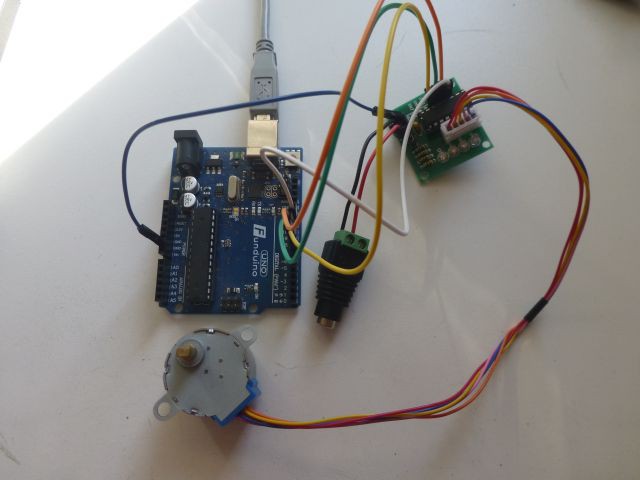
https://www.circuitspecialists.com/blog/how-to-wire-a-stepper-motor/ Not as good, but adds info about 5 wire motors.Drivers are a little harder to characterize. They may be designed for unipolar or bipolar operation, and also provide constant voltage or constant current operation. Unipolar drivers are simply an array of FETs and provide constant voltage operation. The ULN2003 is used to drive small steppers. It is cheap and easy to use. Here's an example.
https://lastminuteengineers.com/28byj48-stepper-motor-arduino-tutorial/
Here is my setup that I used to test the examples in this tutorial.![]()
With this simple way to drive a stepper, why limit ourselves to small motors? Can't a six wire stepper be connected as a unipolar? There are two reasons this isn't done. Only 1/2 as much power is available from the motor since only half of each coil is used at a time. Since bipolar drivers are now very inexpensive, unipolar motors and drivers have fallen out of favor. The other reason is that constant current operation is not as easy for these drivers.
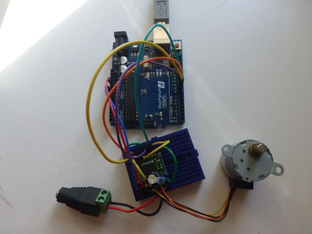
Bipolar stepper motors must be driven by an HBridge. Examples include the TB6612 or L298 constant voltage HBridge drivers.
https://learn.adafruit.com/adafruit-tb6612-h-bridge-dc-stepper-motor-driver-breakout/assembly
https://lastminuteengineers.com/stepper-motor-l298n-arduino-tutorial/
Here's my setup with a TB6612 from Pololu driving a small bipolar stepper..![]()
Since these drivers supply a constant voltage to the stepper, the current is limited by the value of the voltage and the resistance of the motor coils. We measured the resistance when we figured out which wires were pairs, so it's easy to calculate current using Ohm's law. if the voltage is 5 volts and the coil resistance is 50 Ohms, then the current is (i = v/r) 100mA. Even small motors can handle that without heating up. But if the voltage supply is 12 volts and the coil resistance is 2 Ohms, then the current is 6A! That's a lot and will heat up even a larger motor. Now, the fact is that we want to use 12 volts to make the motor move quickly, but we don't need all that current. That's where constant current drivers come in. Using a driver like the a4988, we can drive with 12 volts, yet limit current to only 1 Amp.
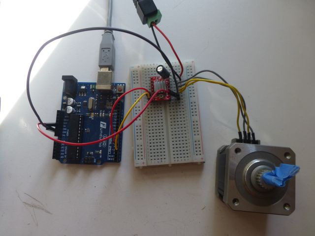
Constant current drivers typically only require step and direction inputs, using only two wires instead of the four control wires needed by the previous drivers. Due to the popularity of 3D printing, the cost of these drivers has dropped significantly in the last few years. These drivers and motors are usually the best bang for the buck if small, cheap motors don't work.
https://lastminuteengineers.com/a4988-stepper-motor-driver-arduino-tutorial/
My a4988 driver/bipolar motor setup.![]()
There is just a little more information to share about these drivers:
You must provide a large (100uF) capacitor between Vmot and ground to protect driver from transients.
Don't connect or disconnect wires to the stepper with Vmot applied! That's true for any driver.
A lot is written explaining how to adjust the current to your stepper. You are most welcome to try any of these methods, but here's the method I've used on many motors. Adjusting the pot on the driver, turn it all the way down, then increase it slowly until the motor performs properly. If you hear a lot of noise from the motor, try turning the current down.One additional topic worth mentioning is microstepping. This means moving the stepper less than a full step per commanded increment. It is a capability built into many drivers like the a4988. The main advantage is smoother motion. the disadvantages are that the top speed is limited and less power is available. Since AccelStepper doesn't care if microstepping is being used or not, I'm not going to discuss it further but leave it for you to experiment with.
-
2Step 2 First AccelStepper Sketch
Suggested reading: Constructing an AccelStepper Object
Now that you have learned to connect your motor to a suitable driver, and have it hooked to your Arduino, it's time to start a first sketch. The first one we will look at is really simple. Load the UnoAccelStepper_ConstantSpeed.ino sketch (found in the Files section) into the Arduino IDE and follow along as I break it down.
Let's look at the start of the sketch. Here are the first two lines.![]()
We must include the AccelStepper header file in our sketch. That's what happens here.
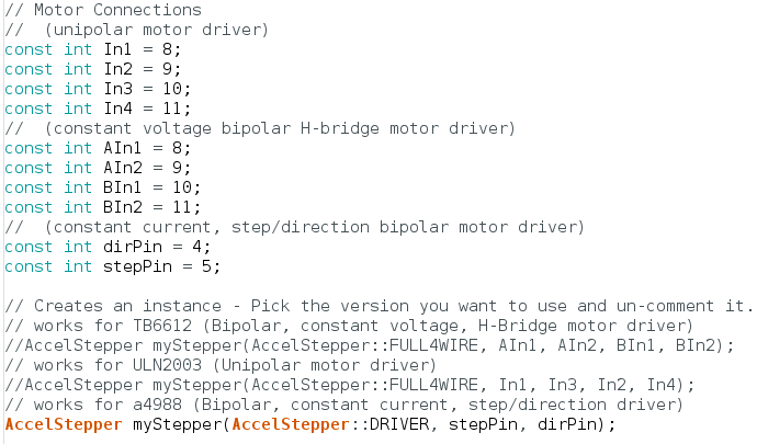
Next we'll define the pins our driver will use. The details here are explained in the Missing Manual. If you skipped the suggested reading and are feeling lost, by all means stop and read now.![]()
Consider each of the three driver types examined in Step 1. First the pins are assigned symbolic names, then the AccelStepper object is instantiated. You can ignore or remove any definitions you don't use; alter the others to the pins your driver uses. I like to leave them all in so it's easy to try different drivers and motors. One additional consideration is to keep the interrupt pins available - D2 and D3 on an Uno.
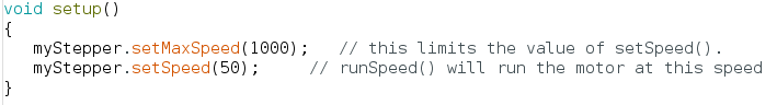
Here's the setup() routine.![]()
Since this example simply runs a stepper at constant speed, we only need to set the maximum speed and the desired actual speed.
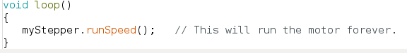
Finaly, here's the loop() function.![]()
The motor will run forever at constant speed.
If you want the motor to run in the opposite direction, change the value of setSpeed() from 100 to -100. Your stepper will run the other way. -
3Step 3 Reporting Results
While the sketch from Step 2 will run a stepper, it would be desirable to have some information reported to the screen. This makes it easy to experiment and build intuition. Let's add some code to report speed and position every second.
To begin, load the UnoAccelStepperExper_1.ino sketch into the Arduino environment on your computer and follow along. Functionally, this sketch is identical to UnoAccelStepper_ConstantSpeed.ino that we just used. We're going to only look at the changes needed to add reporting code.
First, include the ElapsedMillis header file.![]()
Now create an ElapsedMillis object just before the setup() function.
![]()
Note that Serial.begin(115200) is added to the setup() function. This enables writing data over USB quickly.
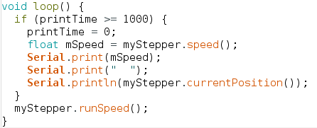
Finally, use the ElapsedMillis object to trigger a report every second.![]()
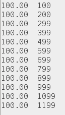
Here's the results of running this sketch, as reported in the Arduino serial window.
![]()
Experiments to try include setting max speed and speed to very high values and see if your motor will run or stall.
Let's learn how to use a pot to interact with a stepper. We'll use the pot to vary the speed. Load UnoAccelStepper_speedControl.ino which includes results reporting from above.
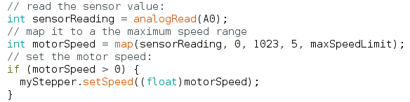
The first part of the sketch is identical to the one we just worked with. A definition for the maximum speed is added, and the initial speed is defined as one fifth of it. The code to report the results is the same. Here's the code added to the loop.![]()
This takes a pot reading, maps it to the maximum speed range, and limits it to positive values (not really necessary). The setSpeed() function sets this speed as the value runSpeed() will use. We can experiment with speeds and accelerations easily now. Connect a 10K pot between 5V and Ground and the wiper to A0. Then run the sketch to control your stepper. Just be sure to instantiate the correct driver. -
4Step 4 Accelerating Your Motor
By now you have seen how runSpeed() is used and the set up that must preceed it. Before we go on you should do this suggested reading.
Suggested reading: Setup Functions and Motion Functions
In the last sketches, we used runSpeed() which simply runs a stepper at a constant speed set by setSpeed() and limited by setMaxSpeed(). But AccelStepper can do much more! As the name implies, it can accelerate a stepper as well. This is done using run(). The run() function will accelerate a motor to the speed set by setMaxSpeed() at the acceleration rate set by setAcceleration(). It will step the motor for the number of steps set by moveTo(), called the target. When the motor nears the target, AccelStepper will decelerate the motor to a smooth stop at the target. The following examples will demonstrate this. For more details, by all means refer to the suggested reading in the Missing Manual.
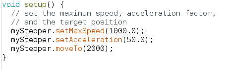
Open the UnoAccelStepperRunSimple.ino sketch in the Arduino environment. You will see that it begins like the previous examples. The changes start in setup(). To use run(), the maximum speed, acceleration, and a target position must be specified.![]()
There is no need to call setSpeed() since it will be ignored anyway. The run() function will accelerate until the maximum speed as set is reached.
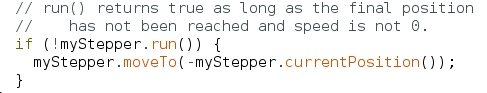
In loop() we call run() as part of an if statement.![]()
As noted, the run() function will return true as long as the stepper is running and the target position has not been reached. When run() returns false, we negate the current position (our old target) and make that our new target. The stepper runs back and forth, accelerating, slowing as the target nears, then reversing and accelerating again. Next, we'll add the code to report every second like we did above. Load UnoAccelStepperRunDemo.ino into the Arduino environment. Let's have a look at it. You'll quickly note that it is very similar to the previous sketch, but run() is just called continuously. This will result in running to the target position and stopping. Further calls to run() cause no further motion.
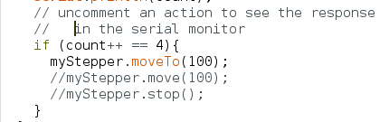
One trick is added in loop(). Besides printing every second, the seconds are also counted and an action can be taken when a desired count is reached.![]() This output can be very instructive to aid understanding of how run() behaves. Here's the output when no action is taken.
This output can be very instructive to aid understanding of how run() behaves. Here's the output when no action is taken.![]()
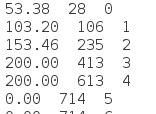
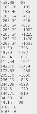
The target position is set to 1500 for this test. The first output column is speed (steps/second), the second is position (steps) and the third is the elapsed time in seconds. We see the motor accelerate to 200 steps per second after 4 seconds, run at constant speed until the target nears, then decelerate to stop after exactly 1500 steps. Next we'll uncomment the first action to set a new target of 100 steps using moveTo(), after 4 seconds.
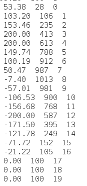
![]()
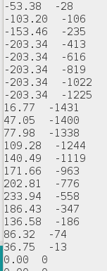
We see several interesting details. As soon as the new target is set, the motor starts to decelerate but is still running in the original direction. It takes about 4 seconds to stop from 200 steps per second. That makes sense because the acceleration is 50 steps per second per second. When it comes to a stop, it immediately begins accelerating toward the new target. As it nears, the motor slows to a stop at 100. Note that speed became negative meaning movement in the other direction. It took 13 seconds to reach the new target and went about 400 additional steps in the original direction before reversing.
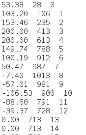
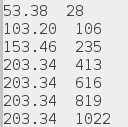
Now we use move() to set a target that is 100 steps from the current position. That's done by commenting out the moveTo() and removing the comments on the move() statement.![]()
The move() happened at step 613 and added 100 steps to set a new target at 713. Note that the motor runs past the new target as it slows to a stop. Then it reverses and moves as quickly as it can to the new target, slowing and stopping.
Our final experiment will use the stop() function. Again, comment and uncomment as needed.![]()
The stop() function will bring the motor to a stop as quickly as possible using the current speed and acceleration. The motor stops in four seconds, decelerating at 50 steps per second per second.
Since stop() uses the current value of acceleration, we can stop faster if we increase it. Put the statement myMotor.setAcceleration(200.0) just before the call to stop(). Here's the result.![]()
We see that the motor stops now in one second! It decelerates at 200 steps per second per second. The limitation to this technique is physical reality. Can your motor actually decelerate at the rate you set? This must be determined in each case.
-
5Step 5 Advanced AccelStepper Control
Suggested Reading: If you haven't already done so, read Using the AccelStepper Library - Overview, and Motion Overview. Read the rest of the Manual as you have more questions.
In this section, we begin learning one of the most useful tools for AccelStepper applications. Our goal will be to accelerate our stepper to a target speed using run(), then keep running at a constant speed using runSpeed(). Using a state machine implemented in our Arduino sketch will allow us to separate command and control inputs from the motion producing functions like run() and runSpeed().
To start, load the UnoAccelStepperExper_2.ino sketch into the Arduino environment and follow along. Note that this sketch is very similar to UnoAccelStepperExper_1.ino that we looked at in Step 3.
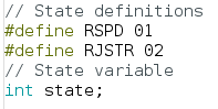
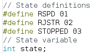
First, we define two states and create a variable called state just before setup().![]()
An initial value of RJSTR is assigned the variable state in setup().
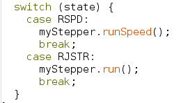
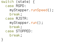
Now let's examine the state machine itself.![]()
As long as state is RJSTR, the run() function is called. If the state is RSPD, the runSpeed() function will be called instead. All we need is a way to change the state.
We do that by adding a conditional to our one second reporting code.![]()
Speed is checked once per second and if it equals or exceeds 200.0 steps per second, the state will be switched to RSPD and the stepper will continue running at that speed indefinitely.
![]()
The target speed is slightly exceeded. If a more precise result is needed, we could test more often or we could set the maximum speed to our target speed. While the state machine in this case is quite simple, we will find that the same approach can be used to control much more complex behavior.
-
6Step 6 Coupled State Machines
Let's add a little complexity to the state machine. Load UnoAccelStepperExper_3.ino into Arduino. Our goal will be to add a control input to the last example to stop the motor after 10 seconds.
First, let's define a new state called STOPPED.![]()
Second, we define the STOPPED action. All we do is: Nothing!
![]()
Finally, we'll add another state machine to provide the control to stop after 10 seconds. The two state machines are coupled by having the same states, and have one state machine controlling the other by changing the state.
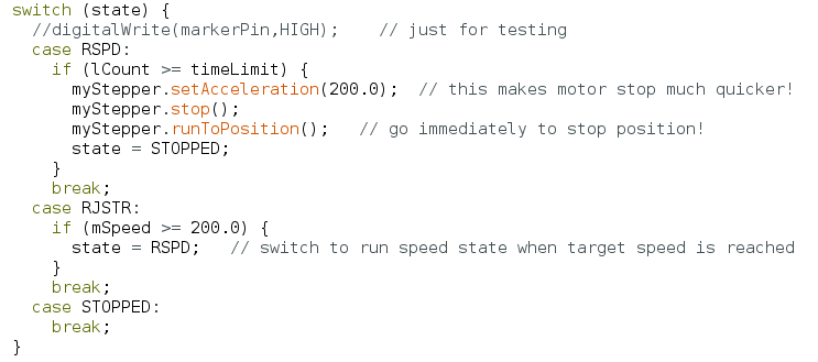
![]()
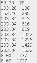
Now when we're in RSPD state, we check to see if we've reached the time limit and then stop. First we increase the acceleration, then call stop() and finally call runToPosition() which blocks further program execution until the motor reaches its final postion (determined by the call to stop()). Then we enter the STOPPED state and nothing more happens as we loop through the program.
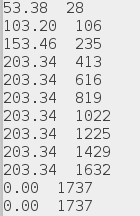
Here are the results.![]()
Since our goal in this tutorial is to understand the AccelStepper library, let us note that the STOPPED state is not really necessary. We can accomplish the same goal by just modifying the control logic. Have a look at UnoAccelStepperExper_3A.ino. Notice that all references to STOPPED have been commented out. As soon as the timer elapses, we change the acceleration and call stop() as before, but now we enter RJSTR state again. The run() function will be called and will step the motor until the final postion (determined by stop()) is reached. Further calls to run() will produce no motion. The results look like this.
![]()
This is exactly the same as the previous results. No surprise since runSpeedToPosition() simply calls run() to do the work.
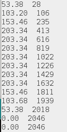
One small difference is that we can now see the effect of changing the acceleration. Comment out the call to setAcceleration(200.0) just before the call to stop(). Now the acceleration will be left at 50. Here's what happens.![]()
Instead of stopping at 1737 steps, the motor now stops at 2046 steps. Since stop() is called at the same point, it just takes longer to slow down.
-
7Step 7 Stop on interrupt
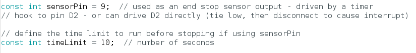
For the final example, let's complicate our state machine a bit more. Load UnoAccelStepperForum_1.ino into Arduino and follow along. This sketch was created in response to a question on the AccelStepper Forum. The stepper will be stopped when an interrupt, such as might come from a limit switch, occurs. After stopping, the stepper is returned to it's initial (home) position. To begin, define a digital pin to use to trigger the interrupt. Pin D9 is used, but you can use whatever pin is convenient. Jumper from the trigger pin to the interrupt pin. Interrupt 0 is used here and maps to pin D2 on an Uno. (If none of this makes sense to you, then google a bit for Arduino interrupts.)
![]()
Note that a time delay before the trigger is defined also. Once the sketch is working, the time trigger can be removed and the interrupt triggered directly by connecting the jumper to D2 to ground to start, then lifting it to trigger the interrupt. This duplicates the effect of a limit switch, for example.
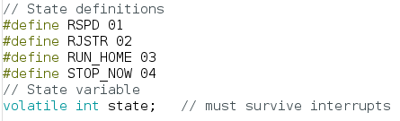
Next we modify the state machine, adding another state. The variable state is declared as volatile so that it can be reliably changed in the interrupt service routine.![]()
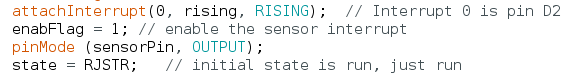
In setup() we add the statement to activate the interrupt service routine, rising(), if a RISING edge is seen by interrupt 0. The flag that will enable the state change in the interrupt service routine is also set.
![]()
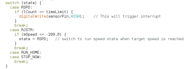
Looking at the first state machine that does the control, note that the action after 10 seconds is to take the sensor trigger pin high. If that pin is connected to D2, then an interrupt will be triggered.
![]()
Note that the initial target and the speed target test are designed to cause motion in the negative direction, opposite what we've seen so far.
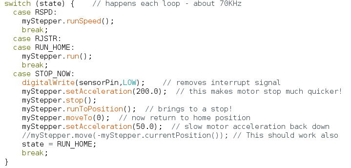
Now consider the other state machine that handles the action.![]()
The main interest here is in the STOP_NOW state. First, the interrupt signal is cleared (won't hurt if it wasn't used), then the acceleration is increased and stop() is called. Then runToPosition() brings the motor to a stop. Finally, the home position is set as the new target and state RUN_HOME is entered and run() will be called to home the stepper.
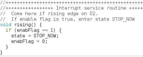
One piece remains and that's the interrupt service routine that causes the STOP_NOW state. When the interrupt service routine returns, the state will be changed and will immediately cause the expected action (just described).![]()
The enabFlag is used to ensure that additional interrupts don't cause unexpected actions.
Let's look at the results.![]()
This is what happens when the timer times out and uses D9 to trigger the interrupt.
What if an asynchronous interrupt is generated as might happen with a limit switch?![]()
Although the timing of the interrupt is random, the result in stopping the motor and homing it is similar - we end up in the same position, as we should.
Using the Arduino AccelStepper Library
Armed with the info in "The Missing Manual", this tutorial shows how to write sketches!


 This output can be very instructive to aid understanding of how run() behaves. Here's the output when no action is taken.
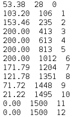

Discussions
Become a Hackaday.io Member
Create an account to leave a comment. Already have an account? Log In.
Thanks for your feedback! Please don't hesitate to suggest additional examples you'd like to see. Also, be sure to check out the AccelStepper forum. https://groups.google.com/g/accelstepper
-- jim
Are you sure? yes | no
This is a fantastic article for "Stepper Motor" control. I've tried a variety of other libraries, but none of them provided the in-depth experimentation like this does. Great Job! Definitely will be returning to it!
Are you sure? yes | no
This whole article is just what I have been looking for. As a Newbie, I understand some of it ! I'll try out each sketch when my hardware arrives. How exciting. As Arnie said "I'll be back".
Are you sure? yes | no