deʃhipu
-
A Touchpad
10/29/2023 at 10:38 • 0 commentsI had this cirque touchpad thingy lying in my drawer for years now, planning to add it to the keyboard, but I never really had the time to look into it. It doesn't help that the way you interface with it is by using an FPC ribbon cable, so you have to find the correct cable and connector. And then you have to write the code to actually make it work. Turns out, once all the pcbs and parts arrive, you can do it in a weekend.
![]()
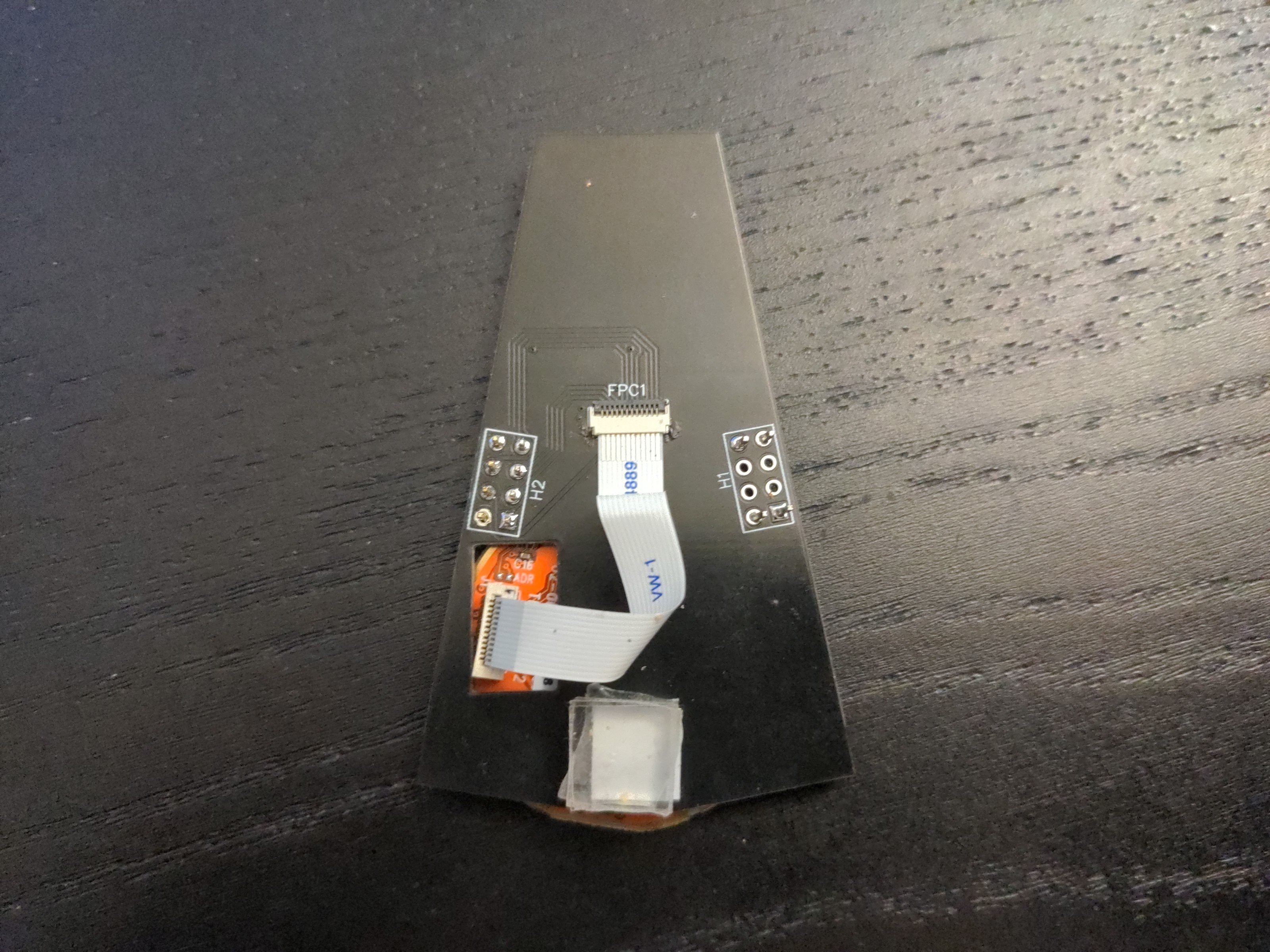
The PCB is pretty basic, it's just the FPC connector and a pin header for plugging into the spare GPIO pins on my keyboard, together with three buttons for the mouse buttons. I made the hole for the fpc ribbon excessively large, just to be safe, but of course it doesn't matter, because it's covered by the touchpad anyways.
![]()
I connected both the SPI and I2C pins, because I didn't know which mode will be best, but that left me one pin short, so I connected the CS pin to GND permanently, since the touchpad is going to be the only thing on the bus. This might by why I couldn't get the SPI mode to work, in retrospect. I also forgot to add the pull-up resistors on the I2C lines, but that was fortunately easily bodged.
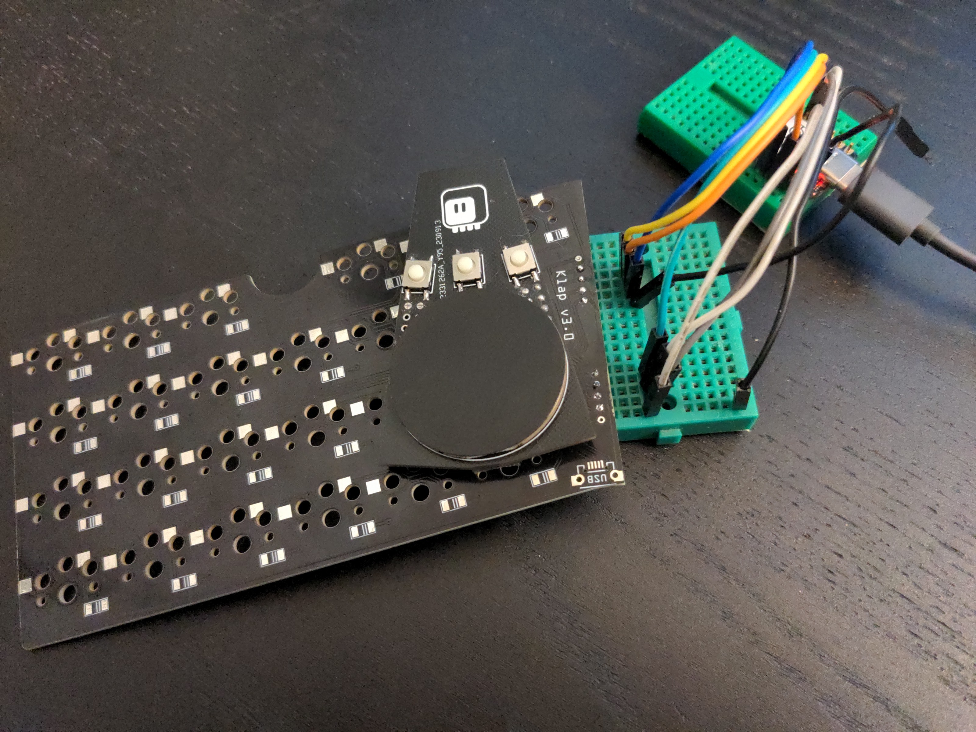
To work on the code more comfortably, without having to use a second keyboard, I made a debugging rig out of a spare half of a keyboard PCB.
![]()
I used Adafruit Cirque Pinnacle CircuitPython library as the starting point, but it turned out to be way too big to fit on the tiny SAMD21 chip I'm using on my keyboard, so I had to write a minimal version. It goes like this:
from micropython import const
import time
from adafruit_bus_device.i2c_device import I2CDevice


_STATUS = const(0x02)
_SYS_CONFIG = const(0x03)
_FEED_CONFIG_1 = const(0x04)
_FEED_CONFIG_2 = const(0x05)
_Z_IDLE = const(0x0A)
_PACKET_BYTE_0 = const(0x12)
_CAL_CONFIG = const(0x07)


class Trackpad:
    def __init__(self, i2c, address=0x2a):
        self._i2c = I2CDevice(i2c, address)

        self._write(_Z_IDLE, b'\x1e') # 30 idle packets
        # config data mode, power, etc
        self._write(_SYS_CONFIG, b'\x00\x00\x00')
        while self.available():
            self.clear()
        # calibrate
        self._write(_CAL_CONFIG, b'\x1f')
        timeout = time.monotonic() + 1
        while not self.available():
            if time.monotonic() > timeout:
                break
        self.clear()
        # rel mode config
        self._write(_FEED_CONFIG_2, b'\x11')
        # intellimouse
        with self._i2c as i2c:
            i2c.write(b'\xf3\xc8\xf3\x64\xf3\x50')
        # feed enable
        self._write(_FEED_CONFIG_1, b'\x01')

    def available(self):
        flags = self._read(_STATUS)[0]
        return bool(flags & 0x0c)

    def read(self):
        data = self._read(_PACKET_BYTE_0, 4)
        self.clear(False)
        return data

    def clear(self, post_delay=True):
        self._write(_STATUS, b'\x00')
        if post_delay:
            time.sleep(0.00005)  # per official examples from Cirque

    def _read(self, reg, count=1):
        buf = bytearray(count)
        buf[0] = reg | 0xa0
        with self._i2c as i2c:
            i2c.write_then_readinto(buf, buf, out_end=1, in_end=count)
        return buf

    def _write(self, reg, values):
        buf = bytearray(len(values) * 2)
        for index, byte in enumerate(values):
            buf[index * 2] = (reg + index) | 0x80
            buf[index * 2 + 1] = byte
        with self._i2c as i2c:
            i2c.write(buf)
Then I had to just connect it to the uKeeb library I'm using, like this:
class Keeb(ukeeb.Keeb):
    def __init__(self, *args, **kwargs):
        super().__init__(*args, **kwargs)
        try:
            i2c = busio.I2C(pin.PA09, pin.PA08)
            i2c.try_lock()
            i2c.scan()
            i2c.unlock()
        except RuntimeError:
            self.trackpad = None
            return
        for device in usb_hid.devices:
            if device.usage == 0x02 and device.usage_page == 0x01:
                break
        else:
            return
        self.mouse_device = device
        self.trackpad = trackpad.Trackpad(i2c)

    def animate(self):
        if self.trackpad is None:
            return
        while self.trackpad.available():
            data = self.trackpad.read()
            data[0] &= 0x07
            data[1] ^= 0xff
            self.mouse_device.send_report(data)
Note that I added fallback code – if the shield is not connected, the keyboard still works, without the touchpad.
Overall, it's much simpler than I expected and works very well. I might make another version of the shield, with the i2c resistors, a jumper to use one of the i2c as cs when in spi mode, and rearranged mouse buttons (right now the middle button is the left mouse button, which may be a bit confusing), but we will see.
-
Version 4
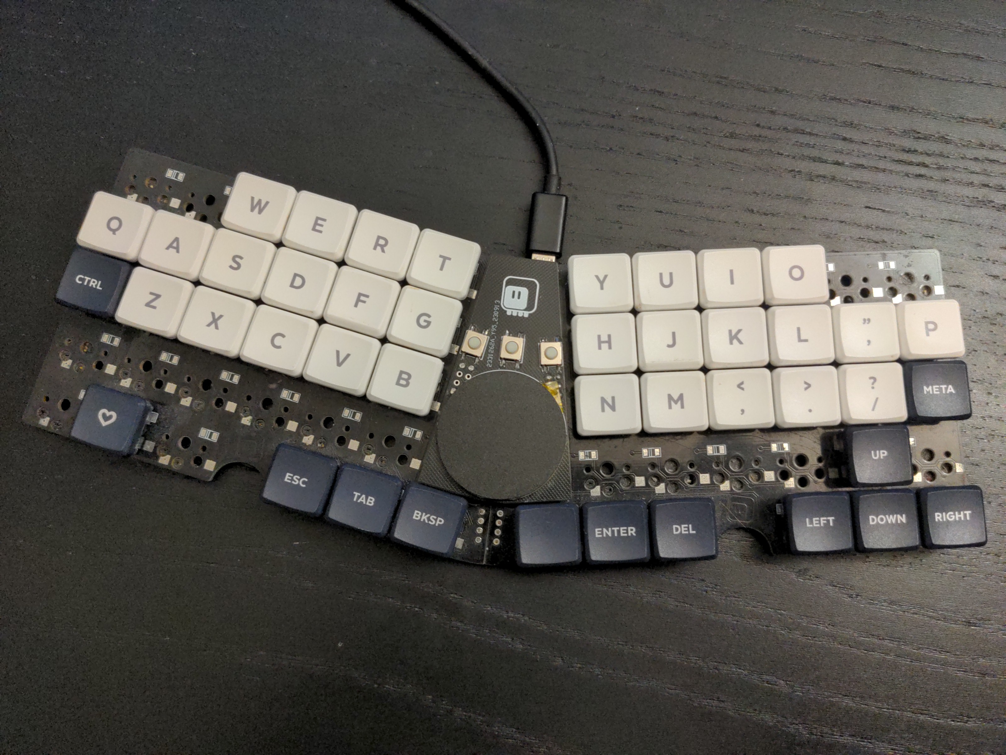
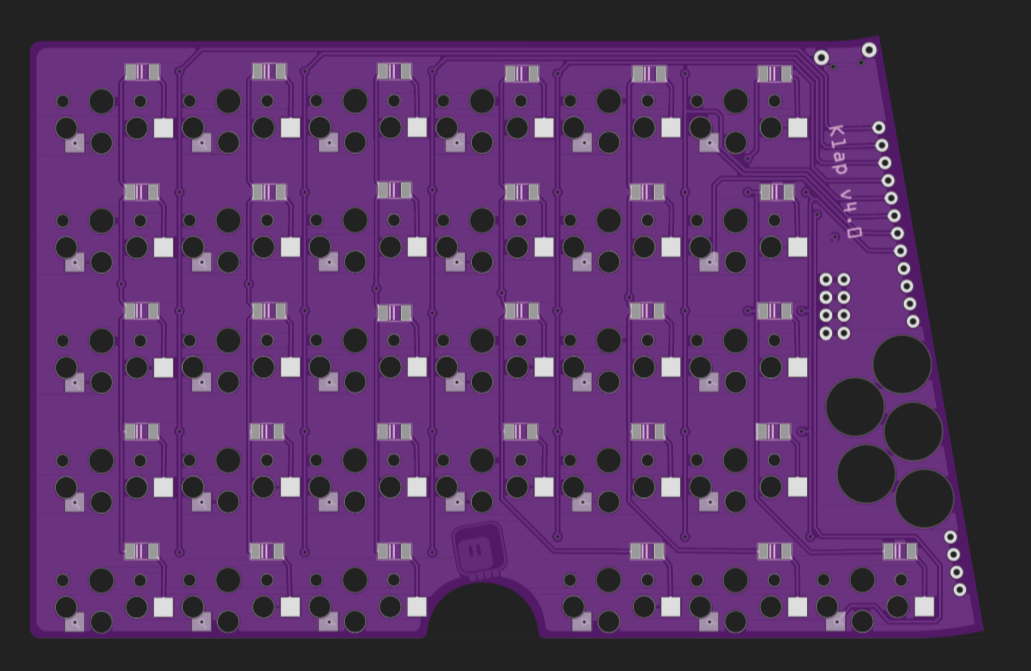
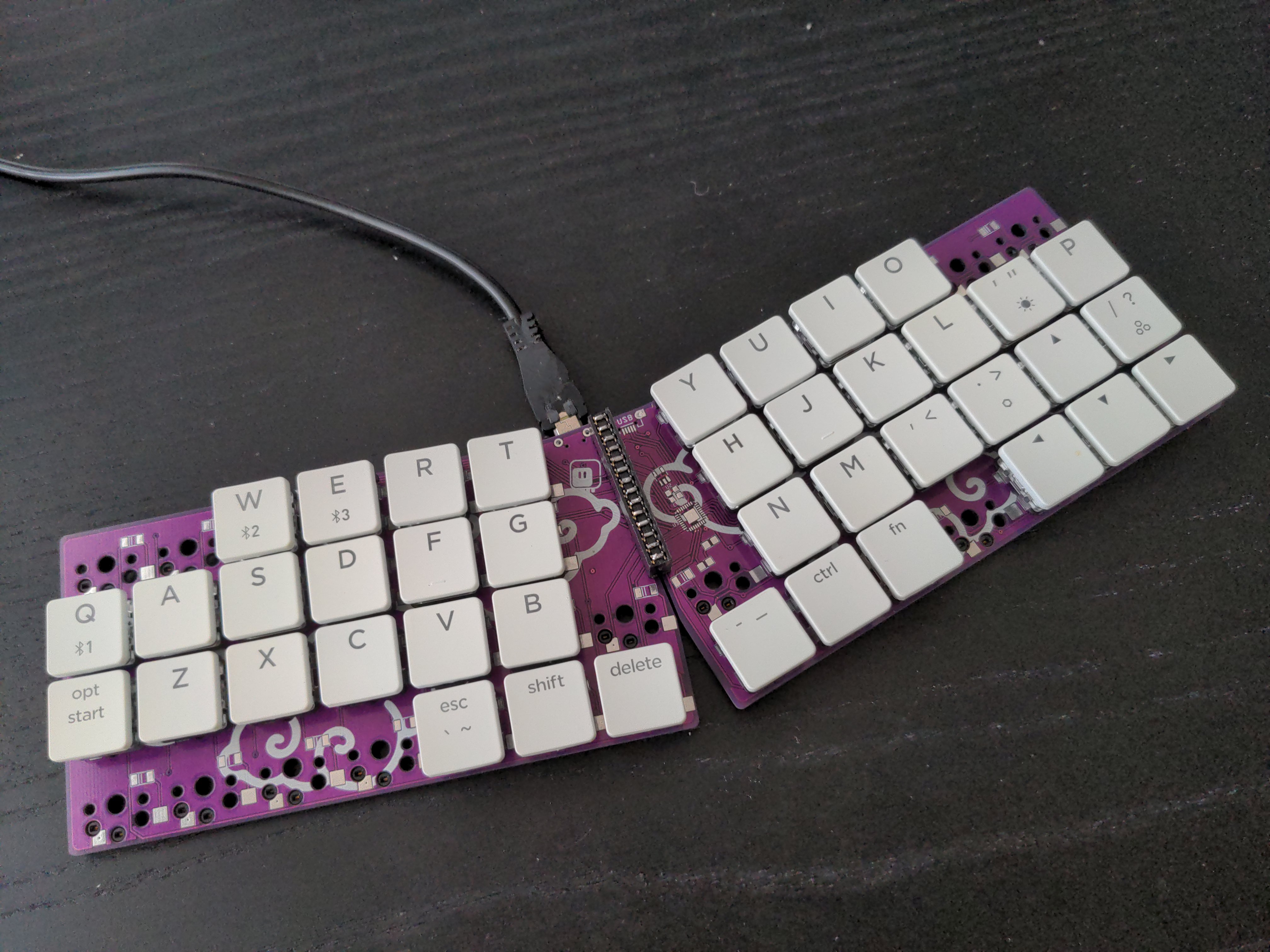
08/22/2022 at 15:35 • 0 commentsI have been using Klap 3 as my main keyboard for a while now, even when it was originally meant to be a travel keyboard. However one thing that is not quite right with it is the thumb cluster being too high – it was intentional, to make the keyboard more portable, but now that I use it every day, I would like to fix that compromise. The new keyboard won't be as travel friendly, and I will skip the magnetic connectors too, but it will have that extra row of keys that will let me move the thumb cluster a bit lower (and move the slash/question mark key back to its rightful place).
![]()
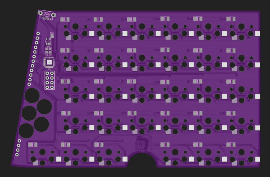
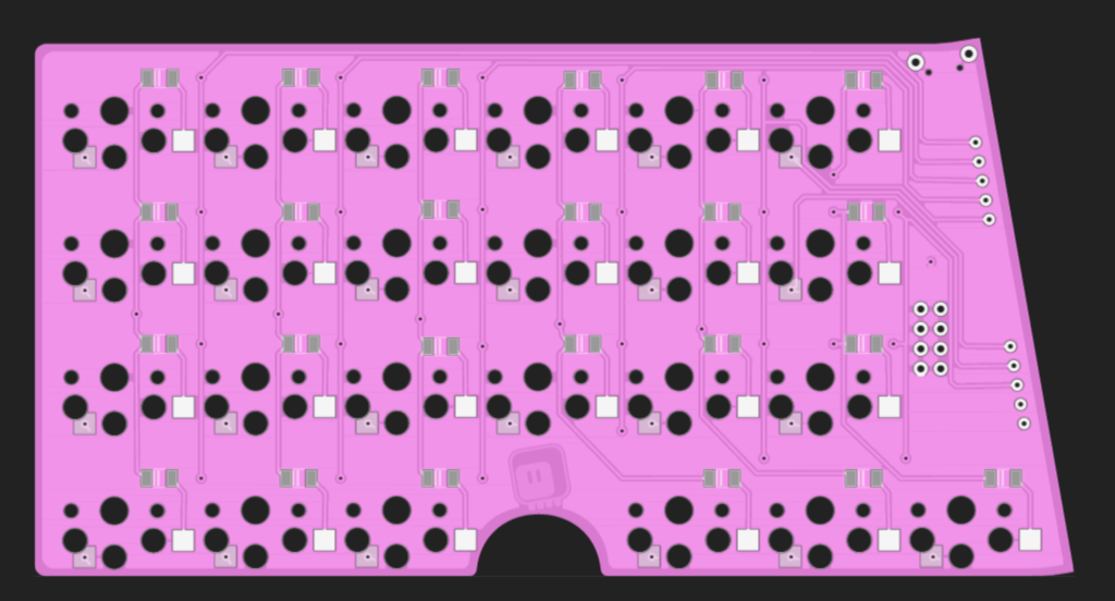
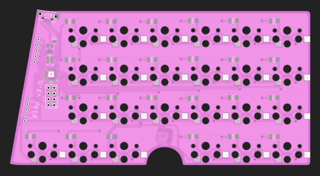
The changes are pretty much a little bit of copy-pasting, and adding one more pin to handle the new row. Nothing too exciting. Again, there was a large empty area of the PCB, so I added some decorative holes there.
![]()
![]()
The PCBs are on order from @Elecrow, so they should be here in a week or two.
-
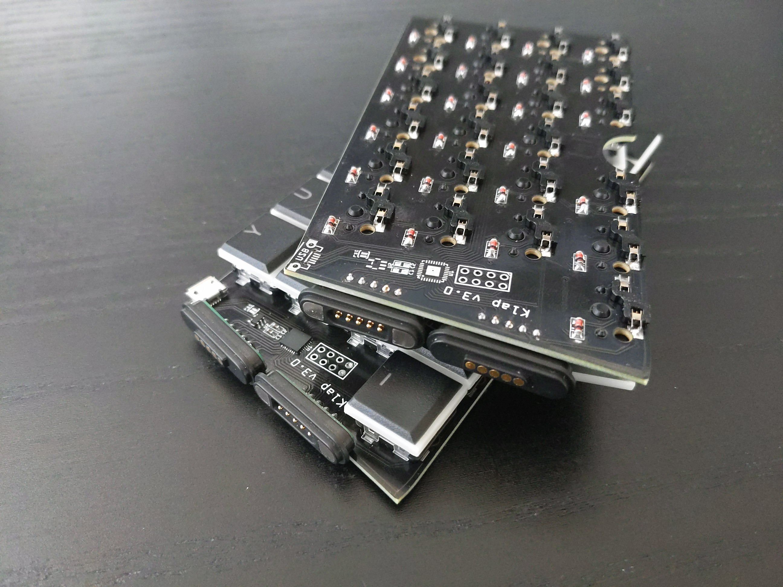
Version 3
04/12/2022 at 15:32 • 0 commentsThis is mostly fixing the mistakes from version 2: the holes are now tight enough to hold the switches firmly, the routing is fixed so the microcontroller and USB socket can be on the top of the right half, as intended, a few diode footprints that were reversed have been fixed too (but still all the diodes are reversed, so you need that flag in software that flips the rows and columns). There are also some changes: the halves are now connected with two magnetic connectors, so they can be easily broken up for transport. However, to do that, I had to limit the number of lines going to the other half to 10 (4 rows and 6 columns), so I had to remove some keys in the weirder positions — I never used them anyways.
![]()
I will post an update with the design files, parts and code for this later.
-
Magnets
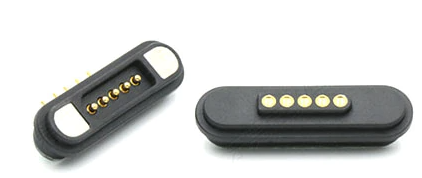
03/20/2022 at 20:29 • 0 commentsSince I have to make one more version of this, because version two had so many mistakes, I thought I will look a little bit at what connectors could be used, and I found this:
![]()
It's basically pogo pins and magnets. This particular one has five pins and is mounted at a right angle, so it seems perfect for my needs if I used two pairs of them. So I fixed the problems with the previous PCB, and made this:
![]()
![]()
I had to remove two keys on each half in order to get down to only 10 lines between the halves (4 rows, 6 columns), but otherwise it's very similar to version two. I'm not entirely sure about the dimensions of those connectors, so I left ample room around them — we will see how they work once they arrive. I'm probably not going to use an actual pink PCB, though.
I also broke out six of unused microcontroller pins (and the power), so I might try doing some modules again.
-
Mistakes Have Been Made
03/20/2022 at 18:11 • 0 commentsThe sockets arrived, and I assembled the keyboard. I used a double-row female header to bind together the two parts, in a way that lets me disconnect them for transport — it was an experiment, and I don't like it very much. The mechanical connection is pretty wobbly and feels fragile, and it doesn't look great. But it's workable, so I went ahead with the rest.
I spent several hours trying to flash the chip and failing, only to finally discover that I soldered the two capacitors rotated by 90° — serves me right to put them so close together. Fortunately that was an easy fix.
A worse problem is the fact that the holes for the plastic parts of the switches are too loose. It wasn't a problem when I soldered the switches to the board, but when using the sockets, the mechanical stability of the switches suffers. I already amended the footprint I used, and the next version will not have this problem. And there will have to be a next version, because of one more mistake...
When I went to program this board, I couldn't get a reading from any of the keys. The program works fine, but no key presses would ever register. I went through the schematic many times to verify it, I went through the physical board to check the connections. Turns out I made a tiny little mistake when I moved the diodes to the back of the board — I swapped which columns are connected directly to the microcontroller on the same half, and which go through the connector. Of course the solution is simple: just solder the chip on the other half, on the bottom of the board, and that is exactly what I did to get it finally all working. However, that also makes the USB port go on the bottom side of the board, and there is not enough clearance for the USB plug to not hit the desk. I have one USB cable where I whittled down the plug a bit to make it fit in such situations, so I could use it like that, but it's not a good solution.
Oh, and of course there were some diodes soldered the wrong way, but that's so normal that I don't even mention it.
So due to the above mistakes, I won't be publishing version two of this project, and will go straight to version three.
![]()
-
Klap2
02/24/2022 at 21:42 • 2 commentsThe PCB for the second version of this keyboard arrived:
![]()
This time I'm using switch sockets, so I decided to add an extra row and extra column to each side, to have more room with experimenting with different arrangements of keys. I also put the connector in the middle a little bit closer to the edge, so I can solder pin headers in there, and have a sort of a "clip" made of a double-row header, to connect the halves together, and still be able to disconnect them for transport. Oh, and since the sockets add a few millimetres to the bottom anyways, I moved the diodes to the bottom too.
Right now I ran out of the sockets, so the PCB is waiting for more to arrive.
-
Assebly
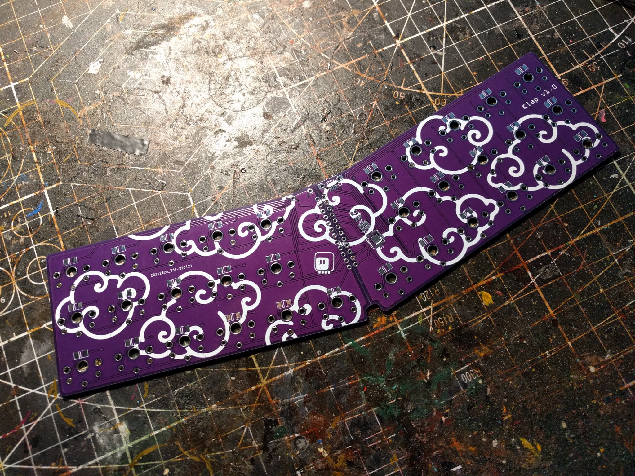
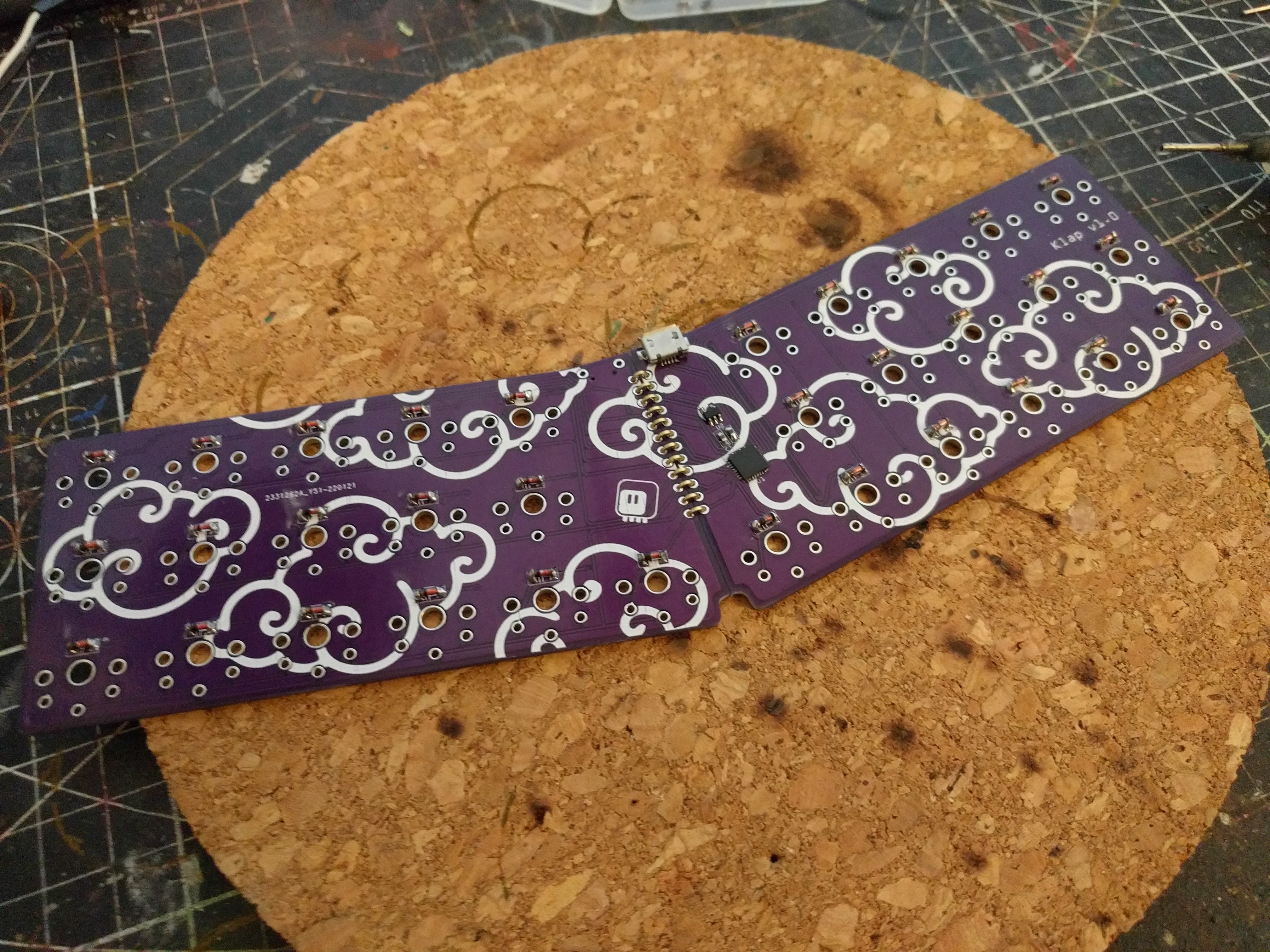
01/31/2022 at 17:58 • 0 commentsThe PCBs have arrived, and I did the usual assembly. Nothing especially exciting here:
![]()
![]()
-
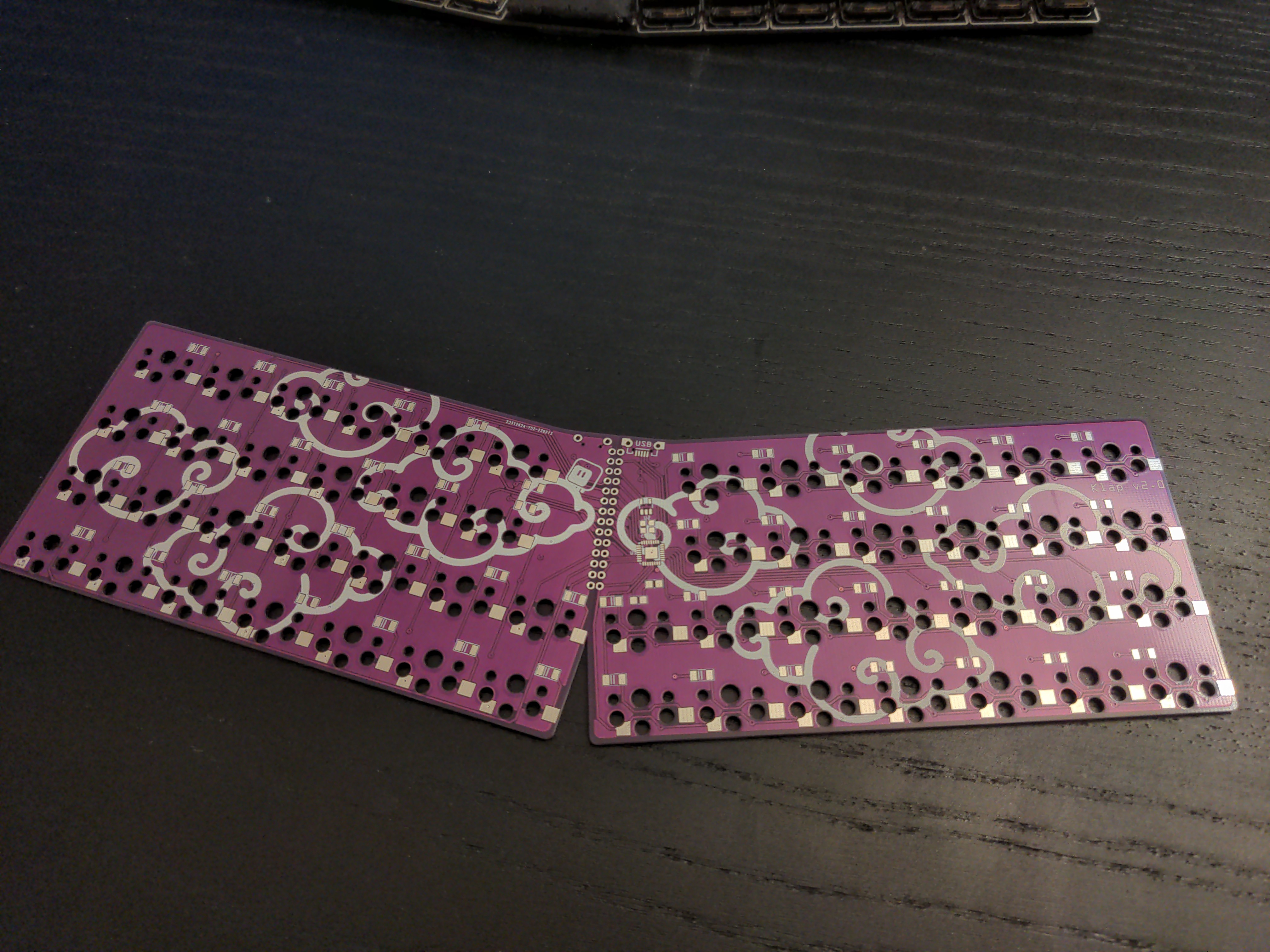
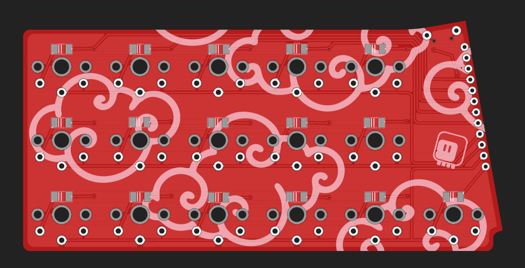
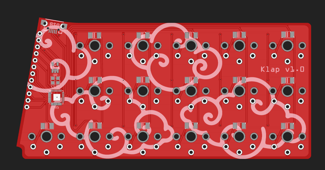
PCB Design
01/31/2022 at 17:06 • 0 commentsI really started this to have an excuse to try the new version of KiCad, but after half an hour I gave up and switched back to Fritzing. Just like in the #Kleks Keyboard, the PCB is reversible and constitutes a half of the keyboard, the other half is a second copy of the same PCB, but flipped over.
![]()
![]()