Details
Entry by: Tim
Technology: Skywater 130nm CMOS
Size: 3 DFF, 1 NAND, 1 AND, (1+ AND for clock gating) ~ 10x10µm² on the IC.
This is a submission for tinytapeout that combines 500 very tiny digital designs into a single ASIC to be manufactured by eFabless open shuttle program. The maximum allows space on the die is 100x100µm² and the design can use 8 inputs and 8 outputs. Both, of course, still rediculously oversized for a minimized electronic die!

Design entry was done using Wokwi, shown above and linked here. The design is based on the non-inverting johnson counter shown before. Since both positive and negative outputs are available, the decoding logic reduces to a AND and a NAND.
The schematic entry is converted to a verilog source by Wokwi:
 assign io_out[0] = net3;
  assign io_out[1] = net4;
  assign io_out[2] = net5;
  assign io_out[3] = net6;

  and_cell gate1 (
    .a (net9),
    .b (net10),
    .out (net4)
  );
  dff_cell flipflop2 (
    .d (net3),
    .clk (net12),
    .q (net10)
  );
  dff_cell flipflop3 (
    .d (net10),
    .clk (net12),
    .q (net5),
    .notq (net13)
  );
  dff_cell flipflop4 (
    .d (net5),
    .clk (net12),
    .q (net9),
    .notq (net3)
  );
  nand_cell gate7 (
    .a (net10),
    .b (net13),
    .out (net6)
  );
  and_cell gate9 (
    .a (net1),
    .b (net2),
    .out (net12)
  );
endmodule
Then a github action in a github repository fetches this, performs synthesis, placement, routing and layout generation.
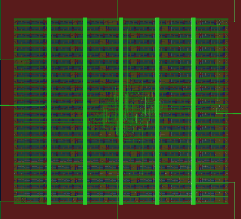
 The generated layout is shown above. Only a tiny part of the actualy space is used. And even that is mostly occupied by the scan chain shift registers, that are used to read/write to the 16 I/O pins.
 Another design I handed in averaged 50000 cells/mm² for mixed cell types. Based on that, we can assume that the 5 cells occupy 0.0001 mm² or about 10x10µm², one percent of the allowable space. I guess this is surely the smallest electronic die, but maybe not the most efficient one.
 Tim
Tim
Discussions
Become a Hackaday.io Member
Create an account to leave a comment. Already have an account? Log In.
Well played !
What about the RESET of the state ?
Are you sure? yes | no
Yeah, somehow the DFF in Wokwi are missing a reset input. I used a non-inverting Johnson counter, hoping that they are initialized all in the same state (either 111 or 000), which are both valid.
Are you sure? yes | no
"hoping"...
yeah it's going to go up in flames then ;-)
Are you sure? yes | no
Very hard to make DFF cell that is not biased and will come up in a random state :) I'll take my chances.
But it's a good point regarding the Wokwi flow, I asked in the discord.
Are you sure? yes | no