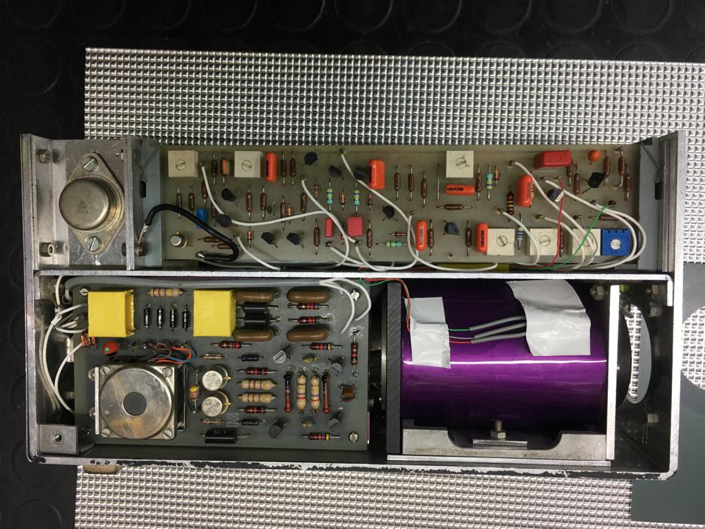
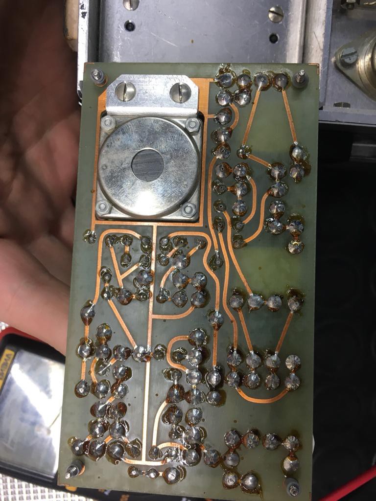
There is one board easy to access and has a little transformer, diodes, caps and stuff that gives you an idea of what the board does.

I labeled the board as P5. It is the one on the bottom in the previous image. It has a total of 7 wires connected to it. One of them is the center of one of the the coaxes (18) connected to the connector of the front pannel. It is powered by the 15V provided by the LM7815.

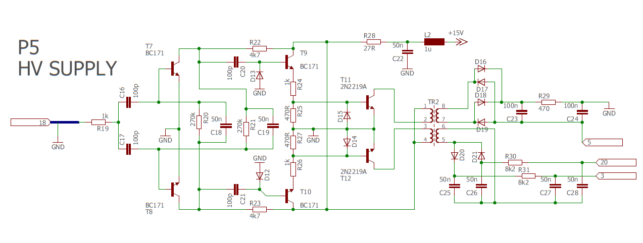
I traced all the board into a schematic in Eagle. The board has some kind of simmetric amplificator with 3 transistors on each side for gain purposes I suppose. It is used to power the transformer, which gives power on two outputs at different voltages.

I tested it with a 5kHz square signal (feeded into the base of T7 or T8, I get in the output the same frecuency) and it works, kinda? I get around 70V in cable 5, around 200V in cable 3 and -40V on cable 20. If I feed the 5kHz signal into R19 I get half the frequency in the output (If anybody knows how this configuration is called, please tell me). I'm waiting for a function generator to arrive so I can test different waveforms.
I'm thinking it works with the horizontal deflection signal (which I presume I have to inject via the front panel connector), which for 50Hz should be 15625Hz. As the frecuency rises, the output voltage rises too, I need to find the frecuency at which this board powers the vidicon correctly, and I think it should give me voltages of around 1000V for the anode.
Also, I've ordered some JFET transistors as I've measured some of them and they were not quite right. I think I'll wait untill I get the function generator before I do more testing, but maybe I make the schematics for another board (an easy one hehe).
I'm sorry if I'm rambling too much and if there are typos. I'm not a native English speaker.
 El Juanan
Discussions
Become a Hackaday.io Member
Create an account to leave a comment. Already have an account? Log In.
See here for a two-transistor bistable circuit which resembles yours: https://www.tutorialspoint.com/pulse_circuits/pulse_circuits_bistable_multivibrator.htm
Are you sure? yes | no
That's fantastic! Thanks a lot, really.
Are you sure? yes | no
BTW I would redraw the schematic to eliminate the bottom power rail. It confuses and has obscured the bistable configuration of the first two BC171 transistors.
Are you sure? yes | no
It seems to be just a normal amplifier with push pull outputs driving the transformer. The pairs of BC171 and 2N2219A form darlington pairs. I think if you redraw the circuit around the front BC171s you'll find that they form a flip-flop, hence the frequency is halved, and the waveform is square so it doesn't matter what the input waveform is as long as it triggers the flip-flop.
The rather low capacitor values after the bridge rectifier feeding point 5 indicate a high frequency is used. The use of half-wave rectifiers for the other two outputs and the relatively high resistor values indicate that they don't supply much current.
Are you sure? yes | no