 suikale
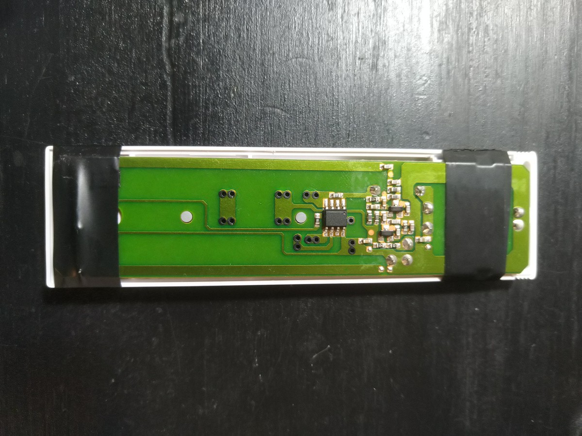
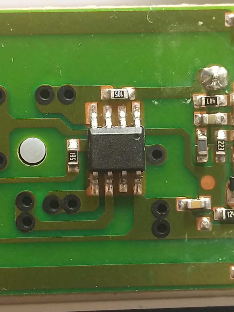
Step 2: Use electical tape to secure the battery and buttons to the PCB leaving the main IC exposed. It is not required to identify the IC, but it would help with the complete reverse engineering process
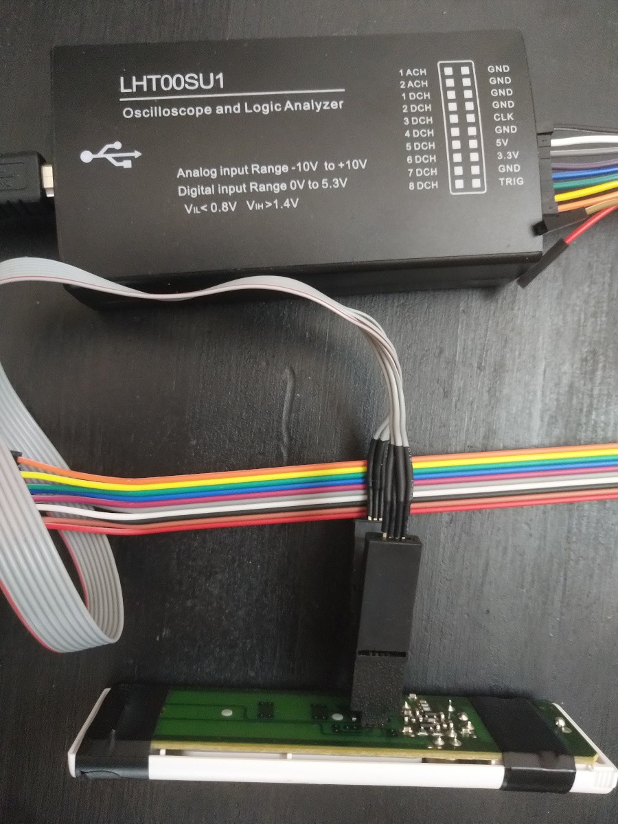
Step 3: Attach a logic analyzers digital pins to the IC. Order of the wires doesn't matter
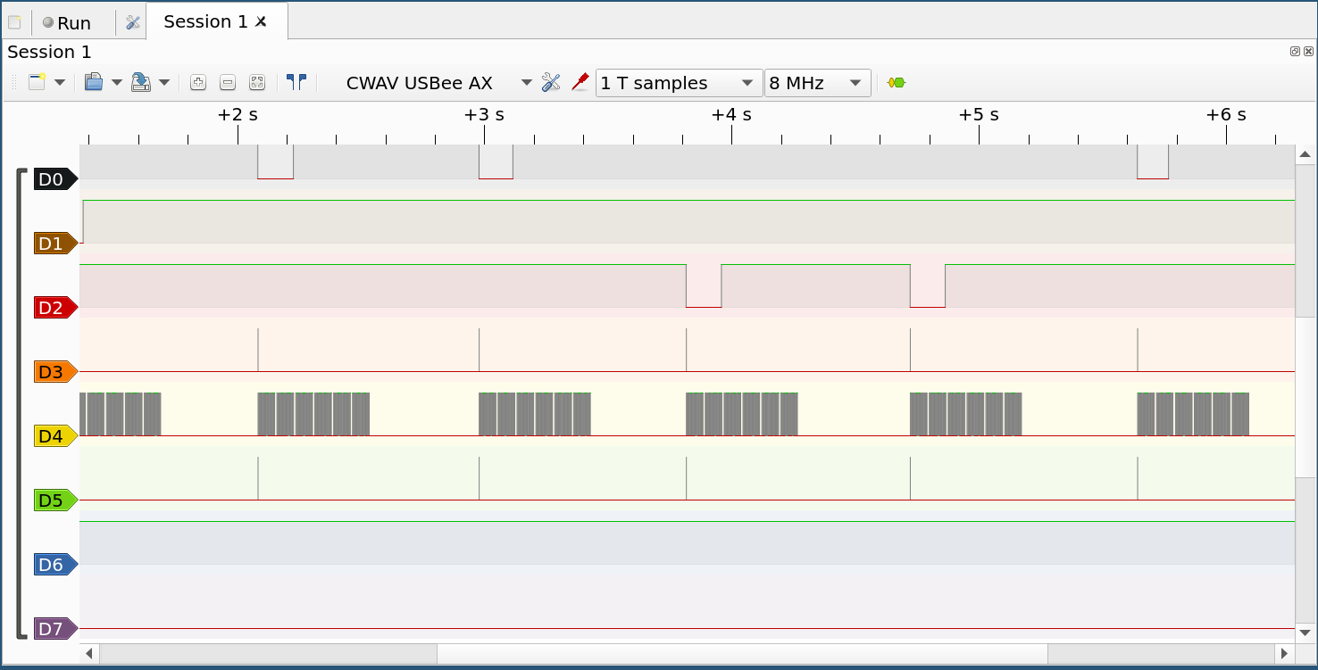
Step 4: Setup Pulseview, start capture and press each of the remote keys. 8MHz is a good quess for initial frequency. D0 is IC pin 1, D7 is IC pin 8 and so on
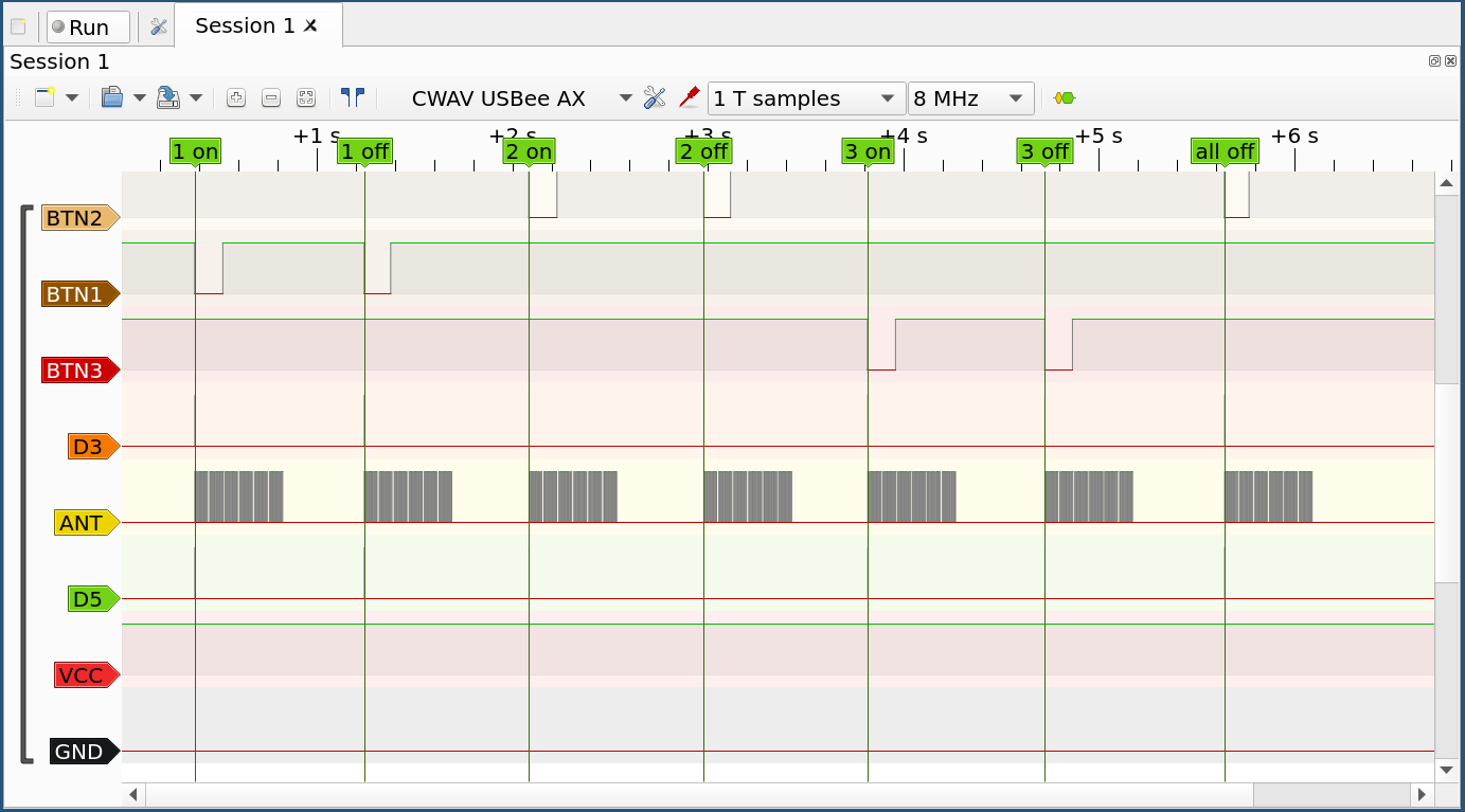
Step 5: Label the pins and figure out what the pins are used for. BTN1 is for capturing 1st row of buttons, BTN2 for 2nd row and "All off" -button, BTN3 is for 3rd row. ANT is for the data sent to antenna. D3 and D5 are used for differentiating key presses for each BTN line and they are not needed here
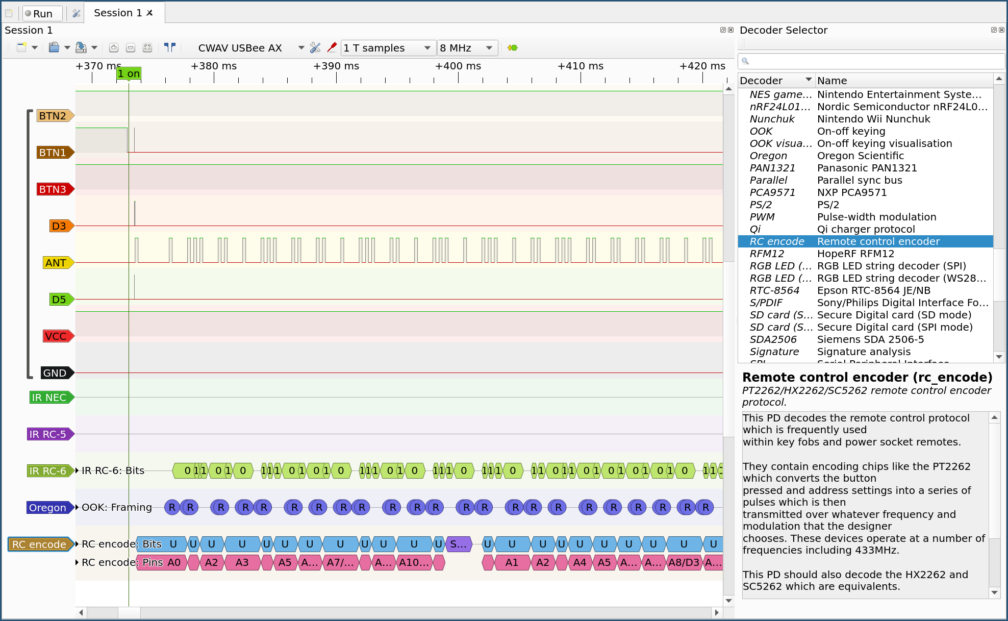
Step 6: Try to decode the signals using Pulseviews decoder selection. Since the every decoder I tried give garbage data lets treat the signal as unknown proprietary data
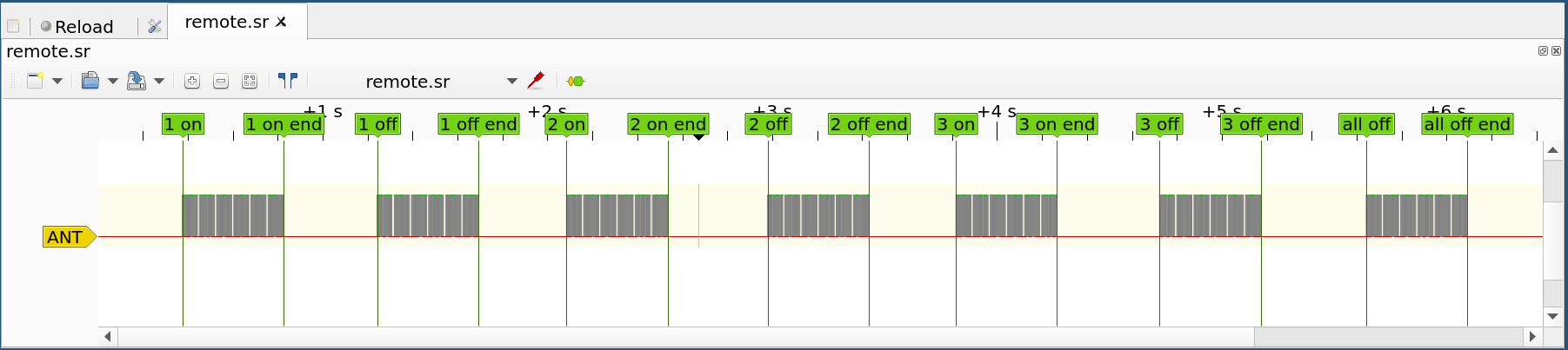
Step 7: Save the unmodified data. Delete all other lines but ANT. Add markers sandwitching out only the essential data. Save each label range as separate .sr file
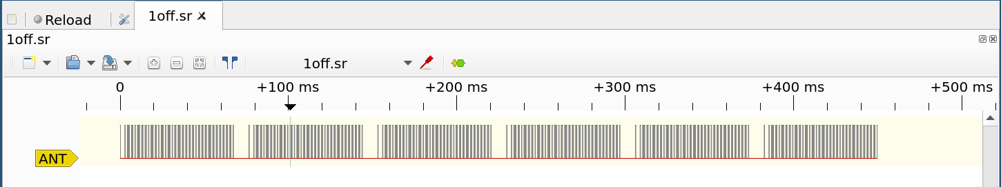
Step 8: We now have isolated the data that needs to be sent through the homemade transmitter to seven different .sr files
Discussions
Become a Hackaday.io Member
Create an account to leave a comment. Already have an account? Log In.