 lion mclionhead
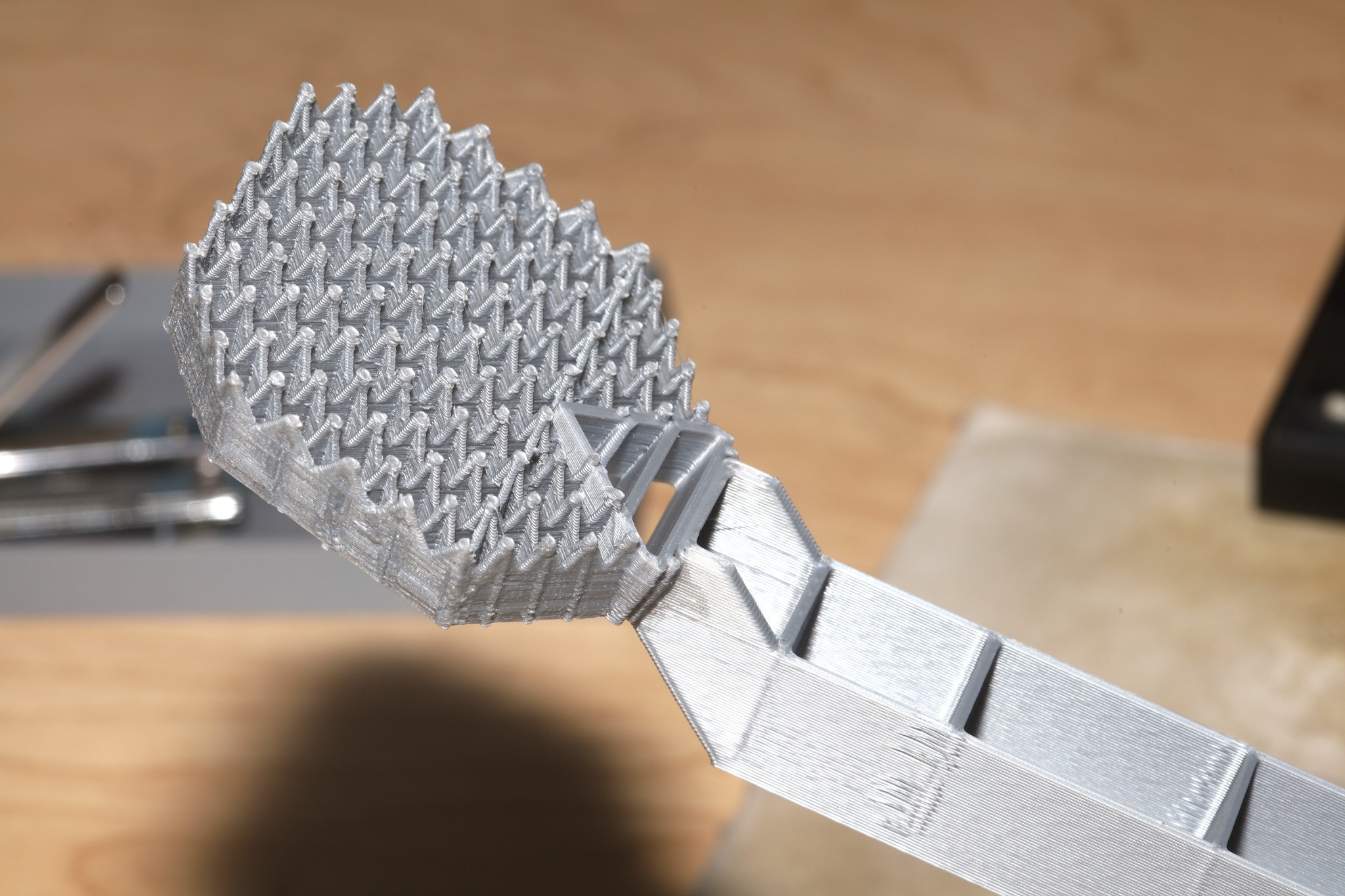
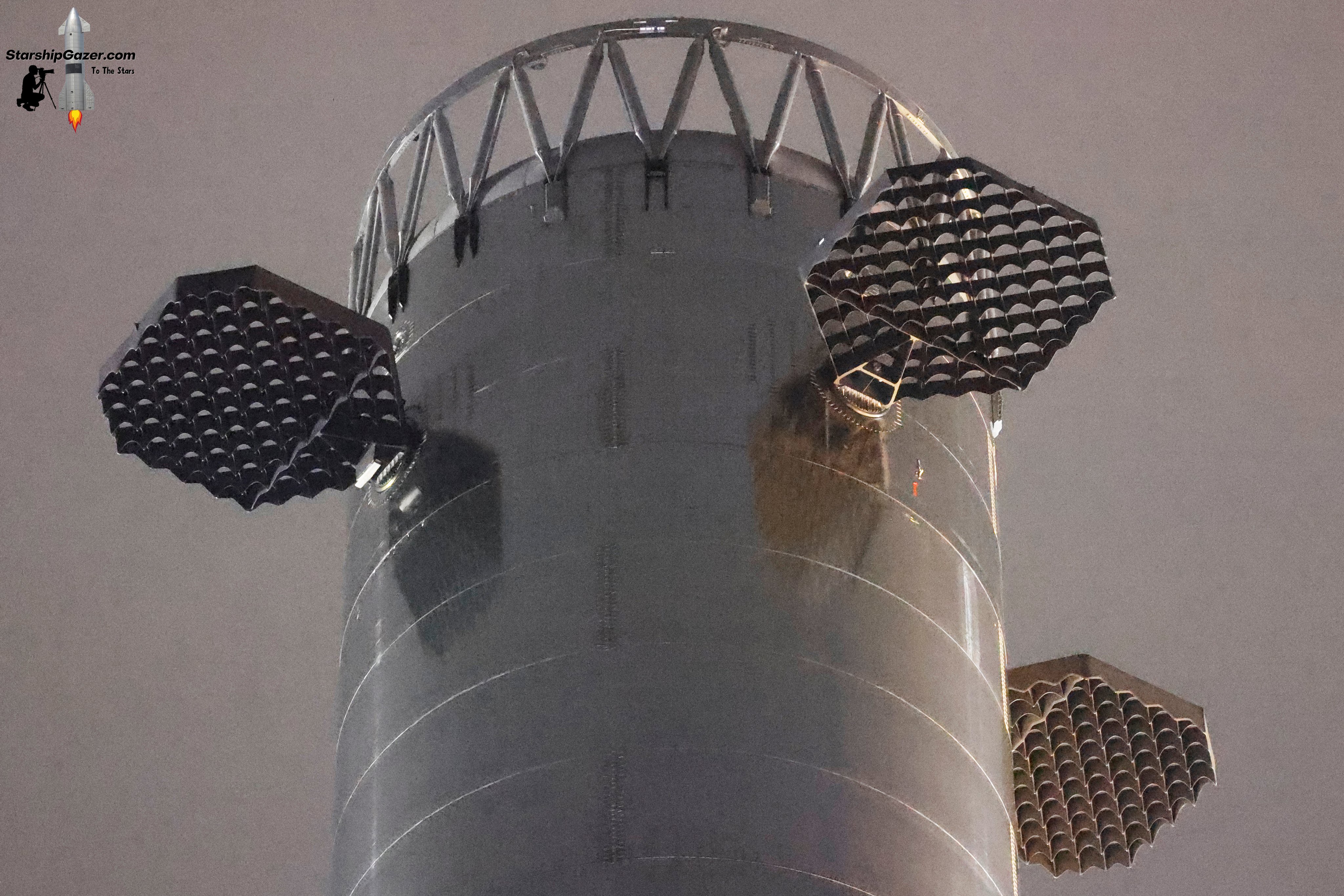
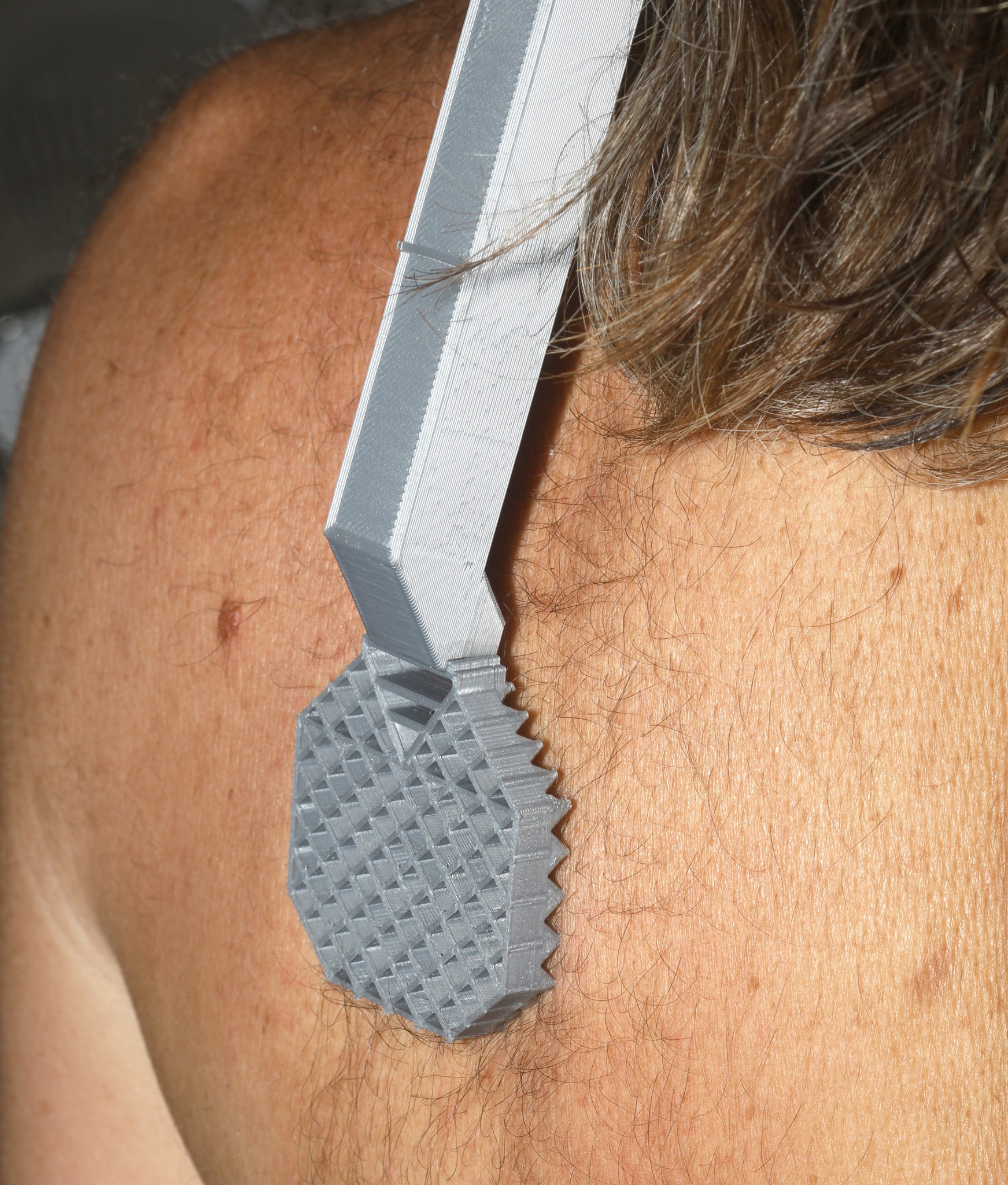
Tried improving the scratch by increasing the handle angle 10deg. Also laminated it with CA since the border walls break easily. It manely scratches with just the last row. The problem is the slanted grid fin is not the optimum shape for a scratcher. It's slanted to force the tail down & the engine section up, increasing the angle of attack.
The side grid fins would be a better match, would be a lot easier to model, but wouldn't look as neat. The catching pins would have to be removed to make it scratch.
The 8mm tall joint joining the handle is very fragile. No matter what, there's going to be a transition to the 8mm height of the grid fin.
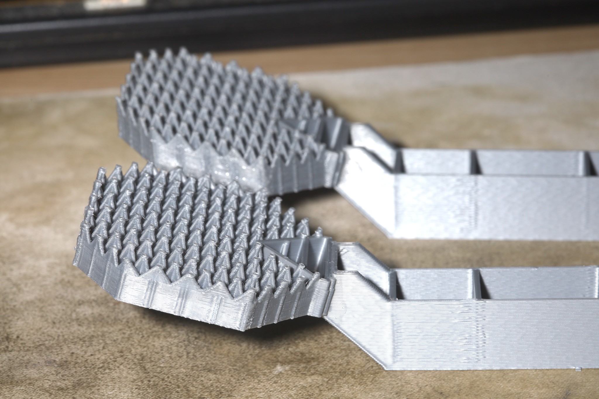
The grid fin printed by the .2 nozzle with .5 walls was very fragile, breaking when pressed against a table. The grid fin printed by the .4 nozzle with .3 lines & .5 walls didn't break with the same pressure.
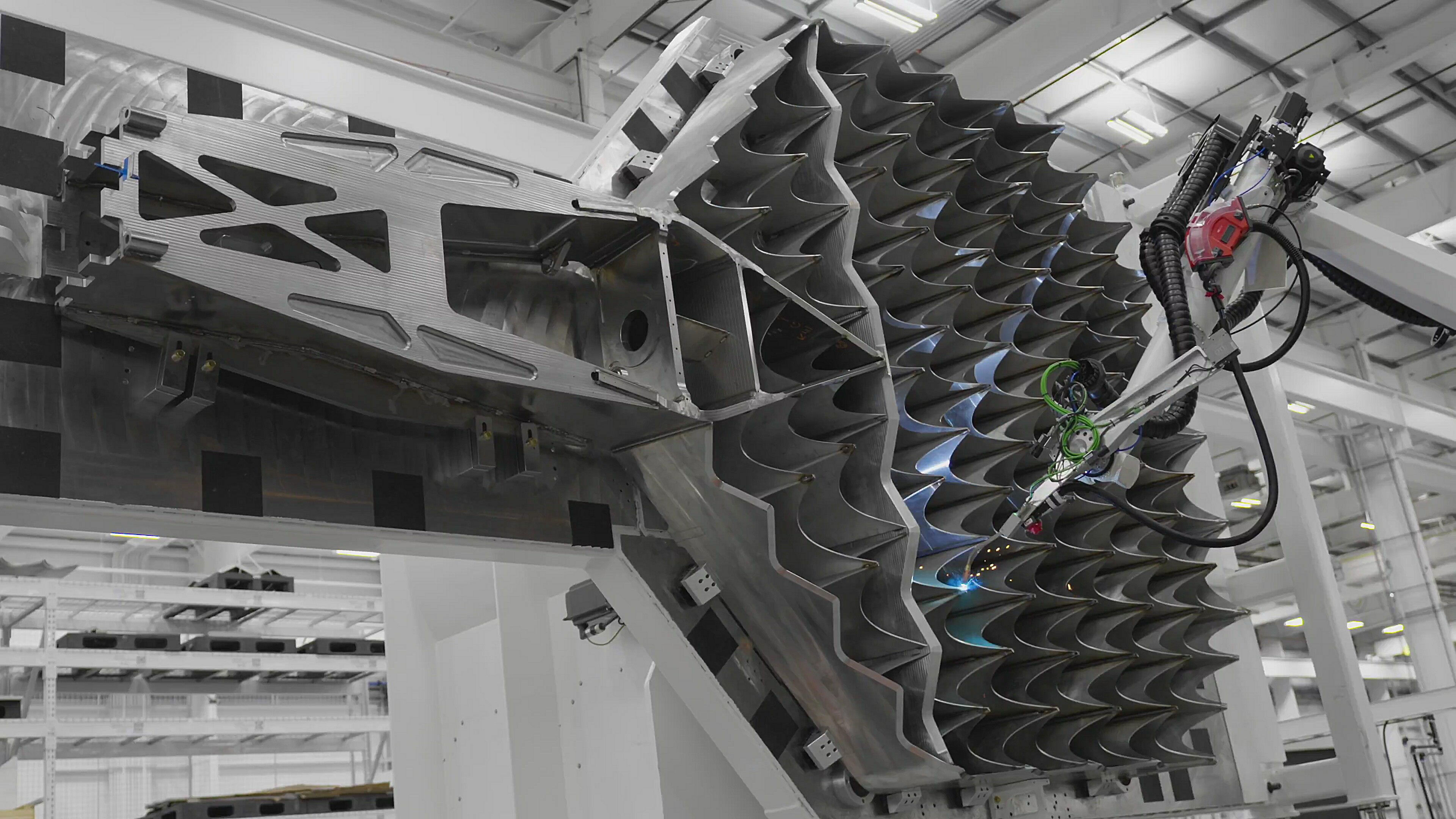
They had another photo of the slanted grid fin.
-----------------------------------------------------
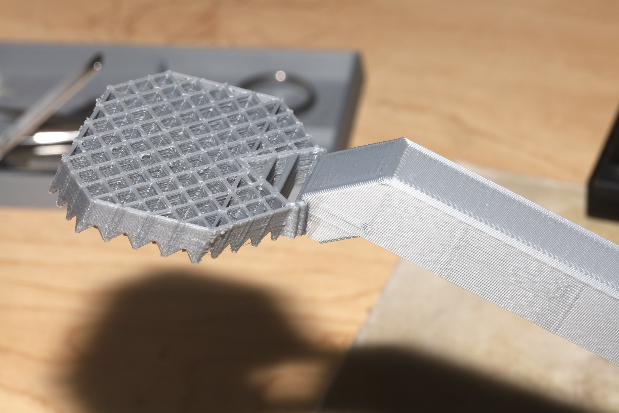
Decided to go with a right angle grid fin to increase the assertiveness.
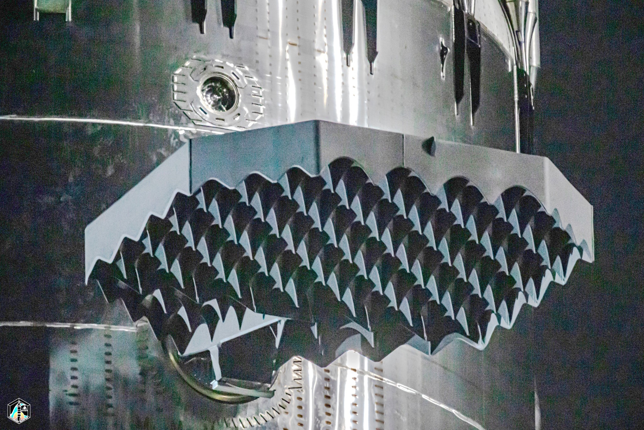
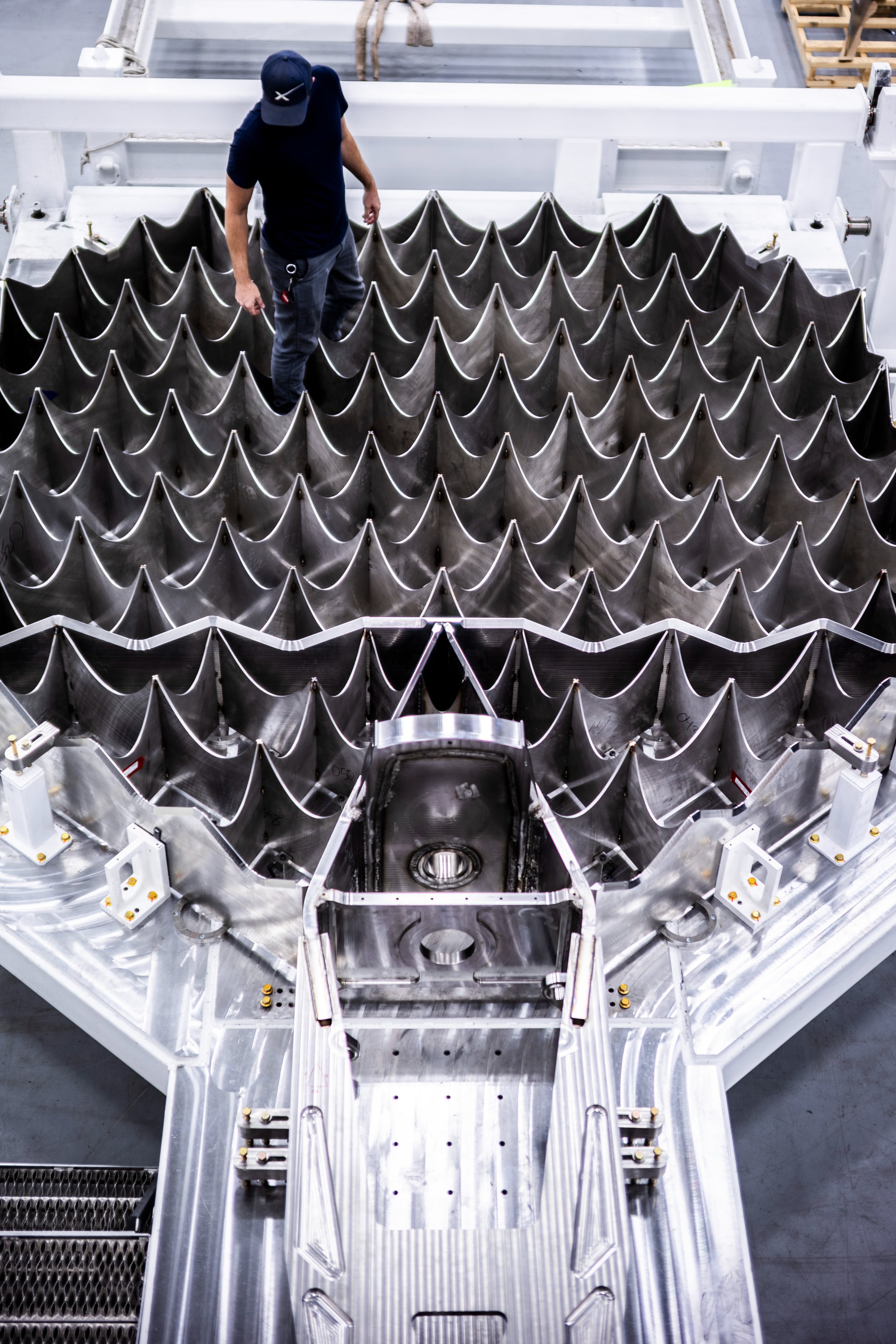
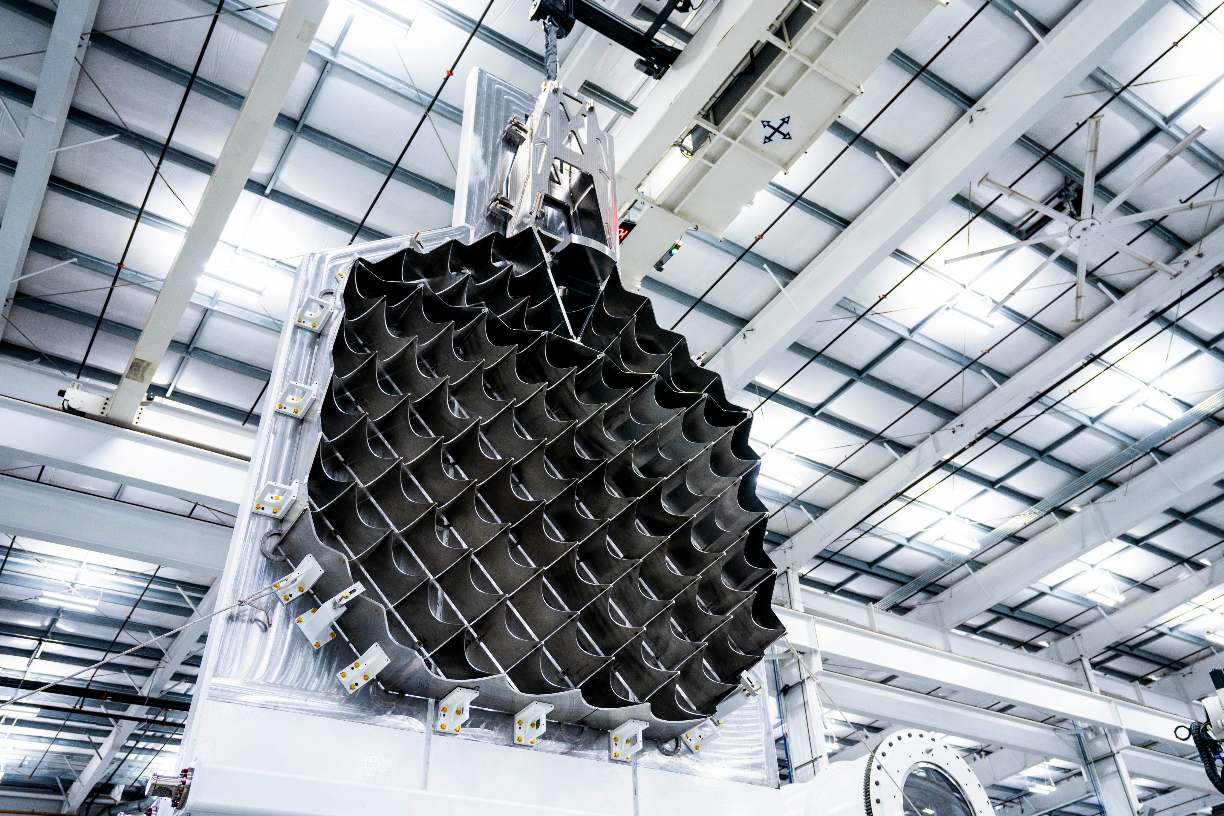
Some photos of the right angle ones showed they're the same dimensions & the catching pin wouldn't be joining us if it was to be a scratcher. The booleans still required fiddling with the threshold in blender.
The 10 deg handle angle still seemed right, even if many positions only use the farthest row of spikes. An adjustable angle would entail a set screw.
Discussions
Become a Hackaday.io Member
Create an account to leave a comment. Already have an account? Log In.