 kelvinA
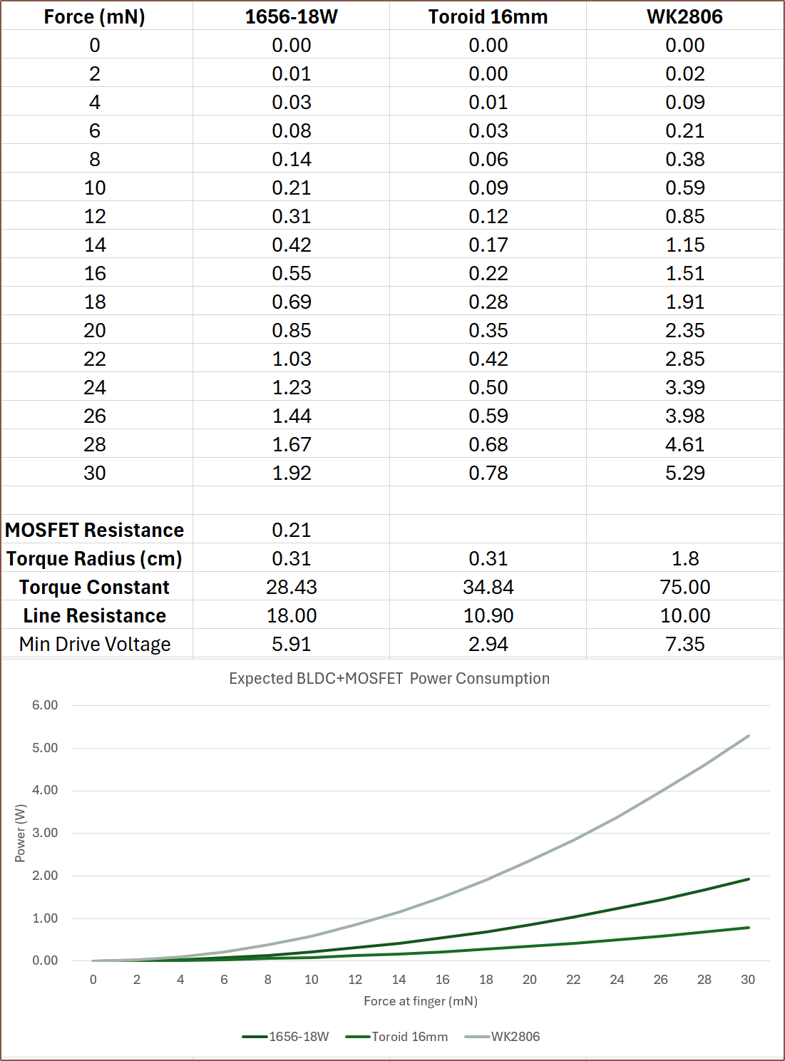
So I've added torque radius into the equation, which essentially is the effective radius of the force if there was no gearing or reductions. This paints a very different picture now that there is a 2.6 : 1 reduction for getting the power from the motor and into the belt.
Additionally, my current understanding that, all else being equal, the proportionality of rotor radius, rotor length and number-of-turns is quadratic, linear and linear respectively. Thus, I've calculated the expected torque constant difference from the motor mentioned in the paper with a 40mm long rotor and 78 turns. There is barely enough space for a 50mm rotor and that would increase the torque constant to 43.5. This calculation assumes that a 4-pole rotor can be obtained. I'd expect less torque if using the 2-pole magnet I found on aliexpress.
The $32 1656-18W motor also now has more favourable power consumption now.
I'll have to see what the torque numbers are when at the new max expected speed of approximately 1200RPM.
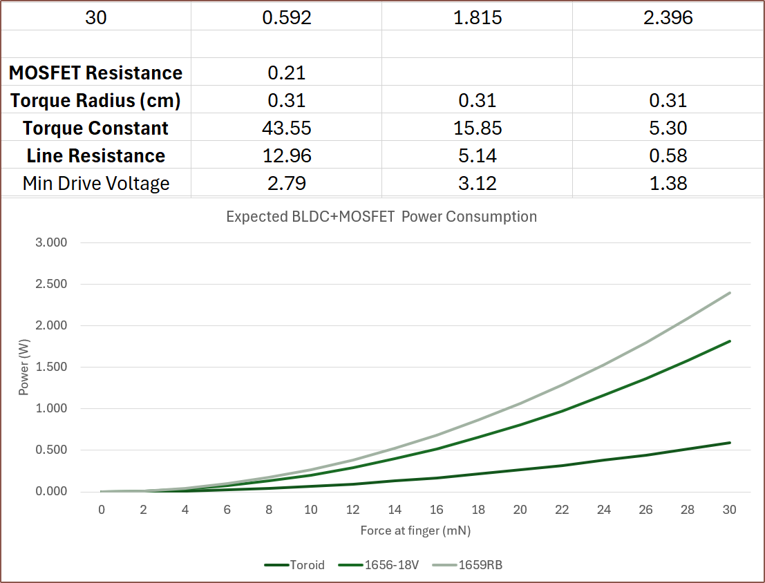
[Apr30] So I can see the amp-turns in action. I can fit 36 turns at 0.25mm diameter, 78 at 0.18 and 106 at 0.15mm, and with a 50mm rotor, they all get essentially 0.6W peak when putting in the resistances and compensating the amp. The only thing that changes is the minimum drive voltage, dropping down to 1.29V for the 36 turns configuration.
Thus, I think the strategy needs to optimised from other perspectives. For example, If I aim for a minimum drive just under 3V, such as the 78 turns configuration, I could use the battery voltage directly. I'm already planning to read the currents drawn by the motor, thus I'd save on voltage conversion losses. With this in mind, the 18V version of the 1656 makes more sense:
Discussions
Become a Hackaday.io Member
Create an account to leave a comment. Already have an account? Log In.