[14:15]

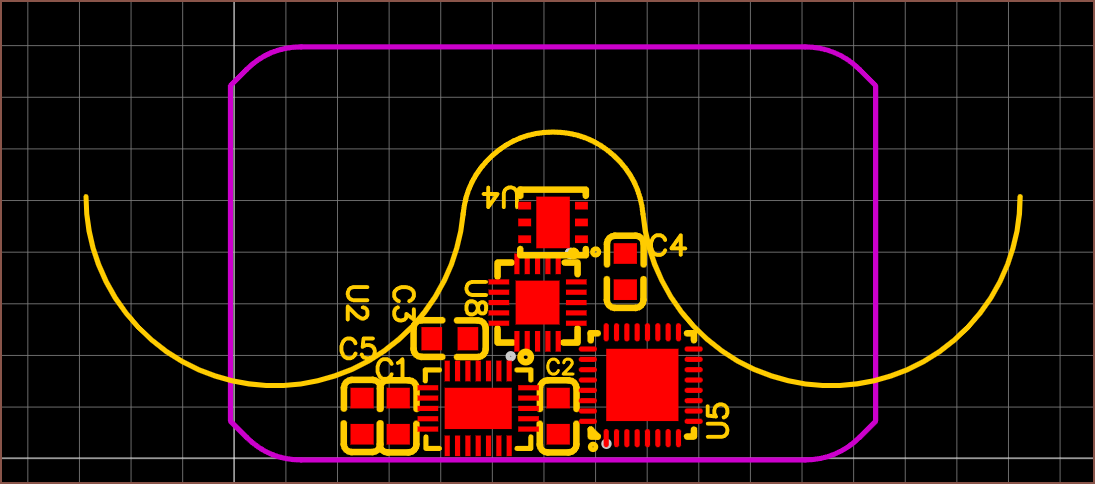
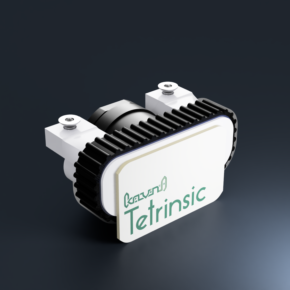
I've already had to increase the size of the board to 25x16mm and reduce some passives to the micromanagement 0402 package, as well as shuffle the IC's around, just so that I could have any resemblance of fitting things into the space provided. At least the motor mount nuts are fully covered by the PCB now, so Tetrinsic should look a bit more aesthetically pleasing for those that enjoy seeing things like Apple's PCBA designs.

Whilst increasing the amount of shared passives and seeing how many more the MCU wants, I found out that the M032 chip is the one with the USB controller. The M032TD2AE has the same amount of flash as the M031 I discovered last log and reduces the IO to 23 pins (from 27). It's 20p more expensive and Digikey has almost 2X the stock. Since this M032 could be more useful in any future electronics projects in the future (due to that internal USB controller), I'm going to use it.
It would be really nice if I can flash the MCU through USB, but if not, I'm likely going to make the 27 ohm resistors (specified in the datasheet) external (since I don't have a lot of board space to go around).
[16:15]

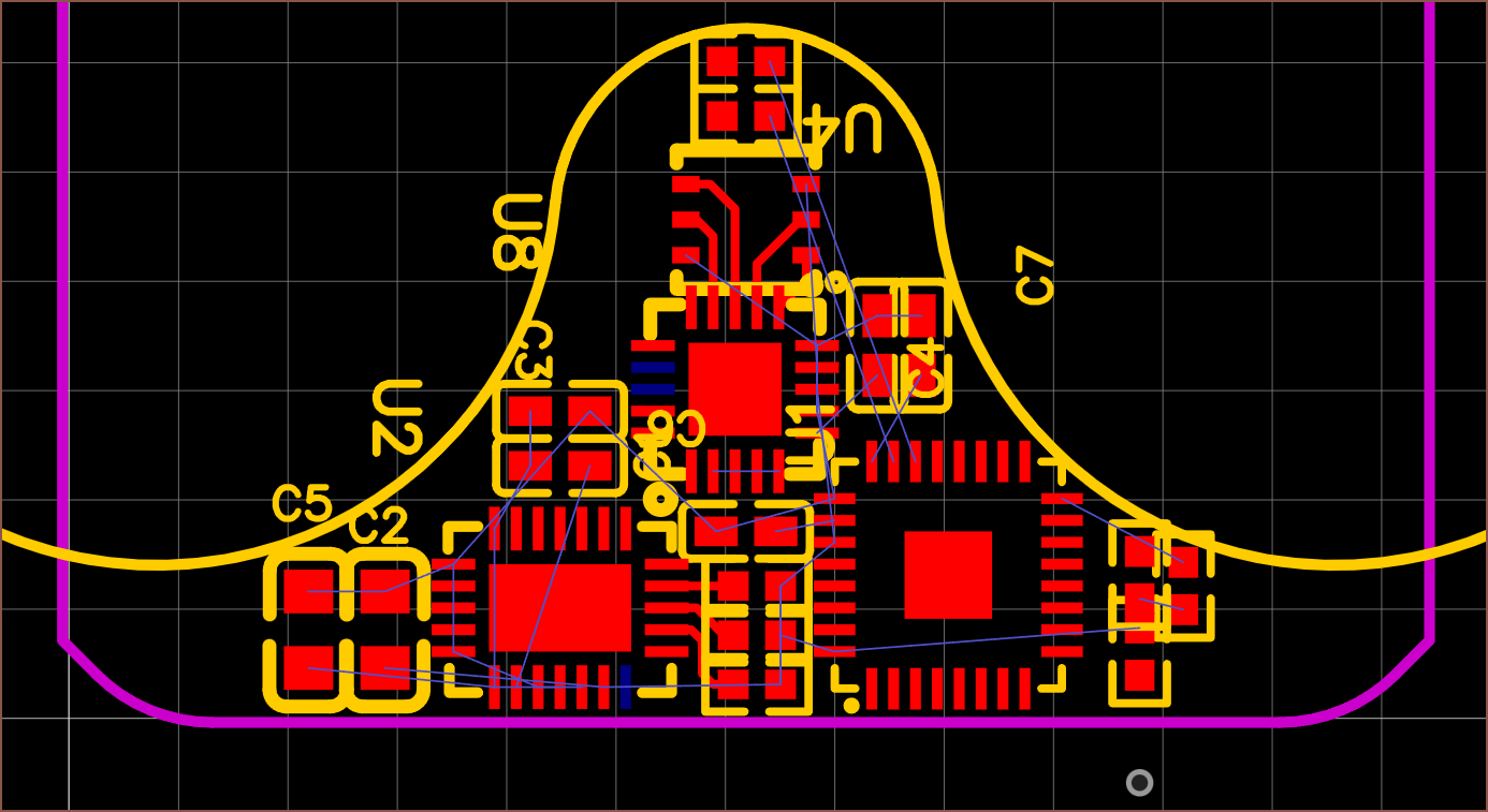
Exciting. I've managed to cram in all the passives I know I need at the moment. Don't mind the silkscreen at the moment. I've also started connecting some pads together to see how close or far ICs need to be so that things are routable.
The blue pads are the not-connected ones that I can delete if needed. I'm assuming that the magnetic sensor doesn't need the pad so I've already deleted it to make routing easier. I've also shrunk the M032 pad so that I can fit vias.
[23:15]
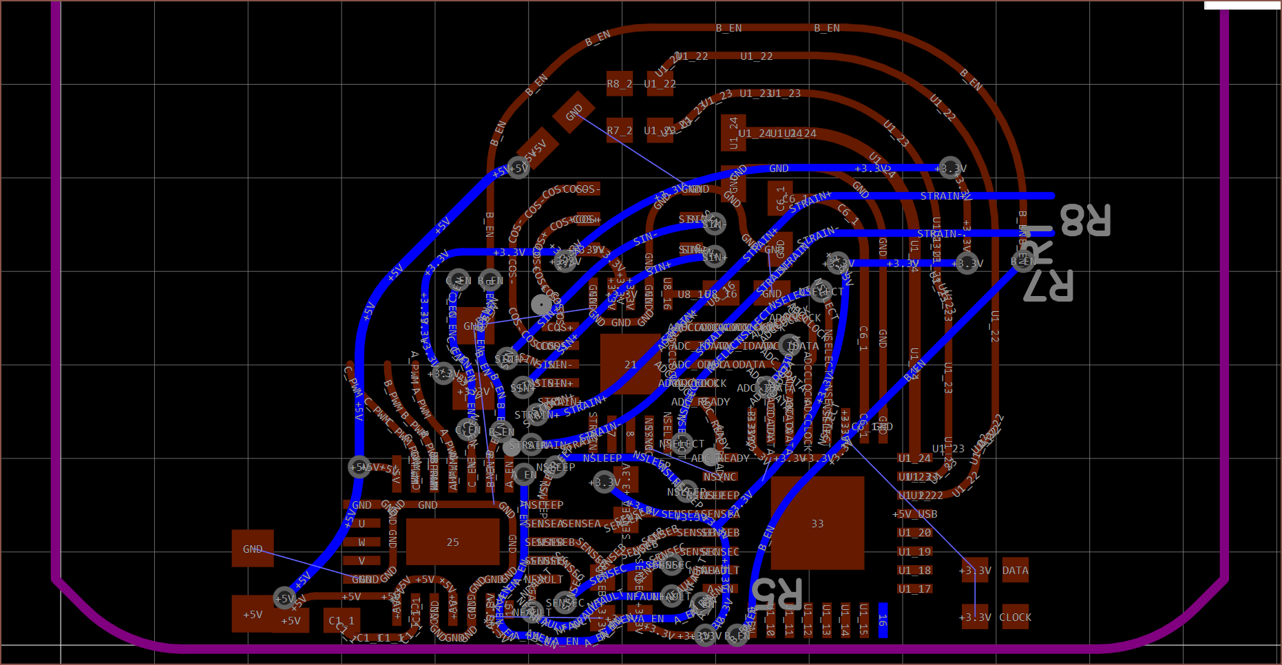
 This is the routing I've been able to get today. The next time I find time, I need to connect the other 4 PWM pins to the MCU and figure out what pin I can use for the I2C feature in the "Universal Serial Control Interface". Then I need to start making some external cable pads.
 I'm also going to need to increase the height of the PCB to 16.5mm.
 kelvinA
Discussions
Become a Hackaday.io Member
Create an account to leave a comment. Already have an account? Log In.