Yesterday, I've mostly been thinking about how I'm going to attach the motor to the rest of the build, and how to go about a 3D printed load cell.
Motor Updates
For starters, I'm thinking of cutting off 2 of the 3 tabs and M2.5 tapping the remaning one. I also was able to easily open up the motor and thread the ribbon cable back through the hole and through the gap between the rotor and stator. The stator electronics seems pretty attached in there, so it doesn't seem like I could 3D print a custom stator mount, forgoing the aluminium one entirely.
![]() Load Cell Thoughts
Load Cell Thoughts
LED or LCD?
I was planning to have a left and right variant of Tetrinsic to give me the most amount of space for this mystery load cell, but then I started thinking "Should I have this thing (the ball chain) LED backlit?" and that soon turned into "Should I use a single daylight white COB LED under a thin, printed sheet, or should I opt for a IPS display where the ball chain slides across its surface?".
I've found both a suitable LED strip and LCD screen, but I couldn't find an addressable LED that would likely fit.
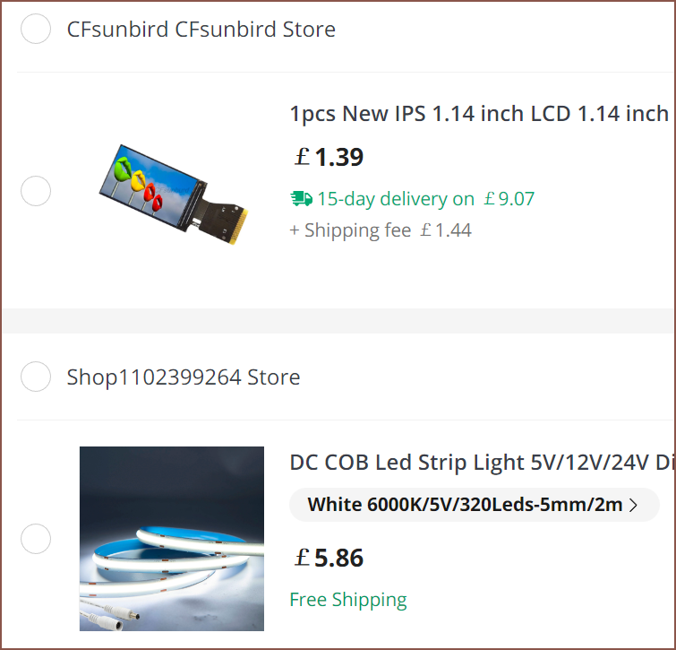 Obviously the screen option is going to be more expensive and more complicated to implement. I'm just wondering if those drawbacks are still worth an implementation. The aesthetic sells, even if one is unlikely to actually see the Tetrinsics in actual use with Tetent.
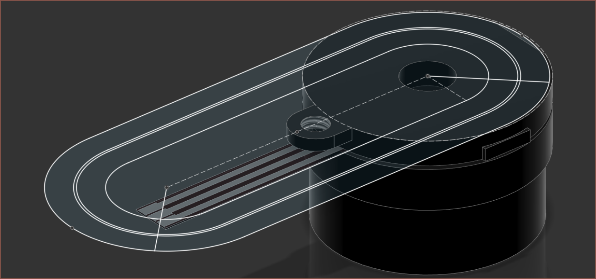
I can see a possible option for the screen version. The screen is 17.6mm, so it covers the entire top section. This means that I wouldn't be able to screw a bolt into the single motor tab and instead would have to do something like a grub screw mount on the cylindrical face of the stator. Half of the initial route, shown in blue, and the possible route, shown in red is shown below.
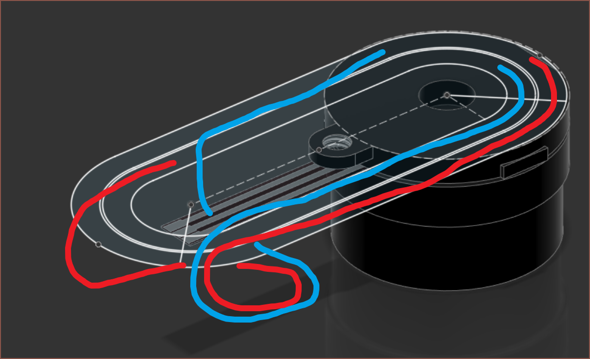
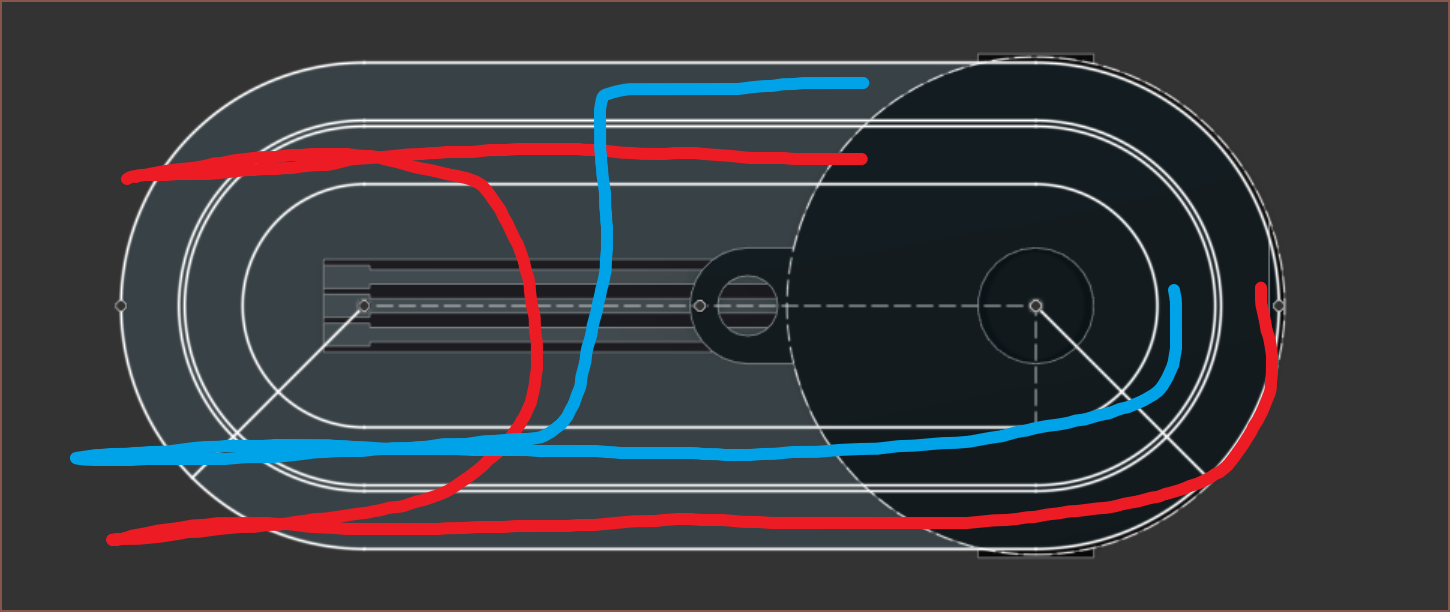 The red path would mean that specific left and right sides don't have to be printed (like the current belt design), but I'd have less mounting space for the load cell.
The LED strip would be more adjustable, taking advantage of the ball chain. Unlike belt loops, I wouldn't have to specifically buy different lengths to make a longer Tetrinsic. Instead, I should be able to just take a length of ball chain and DIY it into a loop without much of a trace. The COB led strip length can also be changed for different applications unlike the display which is fixed at 24.9mm of active area.
Me2: But come on! Think of the aesthetic! And most of r/mechanicalkeyboards is, generally speaking, the same layout with an artistic choice in keycap colours.
I've got an idea. I could design for the screen, then make a 3D printed part that takes an LED (or nothing) instead. Then one could choose between no / solid colour / animated backlighting. Playing all sides, so that the solution always comes out on top.
I'm likely going to need more pins then.
Microcontroller Search
The next M032 up looks decent. 2X the RAM and FLASH for a larger package. Only pennies more.
 If I just look into any USB enabled, 32 bit microcontroller, an option is this tiny BGA:
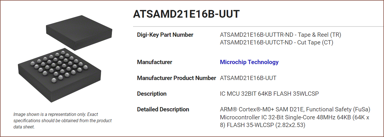 This might not be an option though since routing the pins out might be tough on 2 layers, and there's only 3 more IO pins than the M032 I'm using now. That's also an entire other datasheet that I have to read through.
 This one sounds really good.
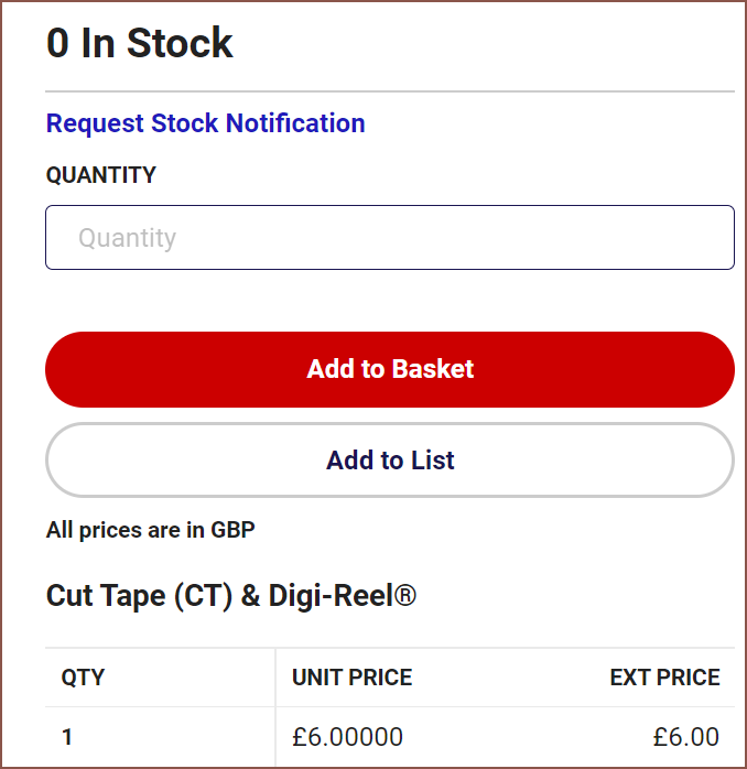 SIX POUNDS?! Outto stock?! What?? What happened to the 385?
 Huh? Is this from some "Marketplace" thing?
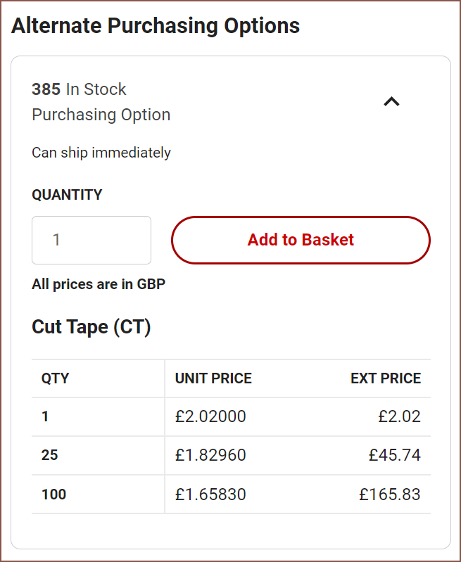 No it looks... perfectly fine... so then why...? Do they just not have Amazon's feature that automatically shows the in-stock listing, or perhaps they deliberately show the higher cost option?
Oh right yes I should also mention why I've completely skipped over the RP2040. Dual core, loads of RAM, 30 I/O pins oh and probably great software support... where's the issue?
 The memory chip is external and there's only 4 analog pins. I think that I only need 4 actually, so this might not be a problem. I've got more worry about the size of this external flash; I predict that I'd have more PCB space but I don't know if I'd have enough for a 7x7 chip and some flash storage. Additionaly, the absolute max rating is 3.63V and the LDO source is 3.45V nominally IIRC (3.3V rated, 3.6V abs max). The LCD is also 3.3V, so perhaps I'd have to take the digital voltage down anyway, but I'll try it and spin up a new PCB if it fails.
Then again, I should look into it though since it supports up to 16 megabytes of FLASH (which, for a microcontroller, sounds like A LOT). The AliExpress boards I found were like £2 or less with 16MB, so it can't be that expensive. I'm assuming it's the relatively large looking 8-pin chip.
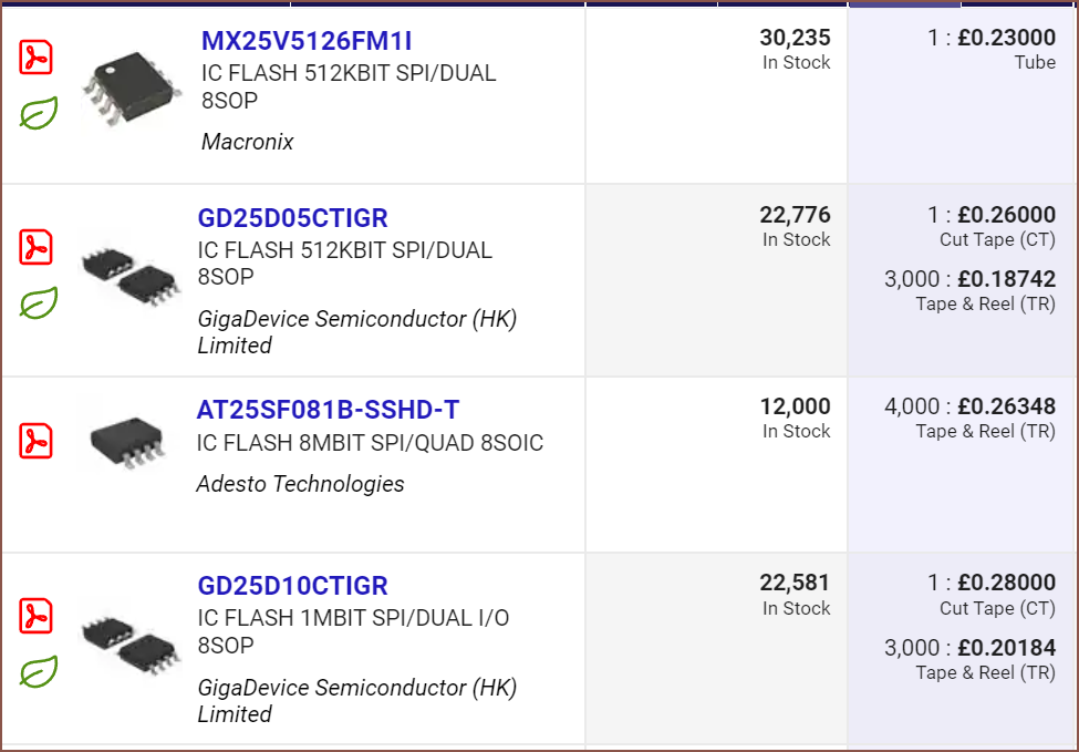 Wow. They're all in this standard 8SOP package and really cheap. I don't think I'd ever have to worry about compile space with 1 M...bit? Wait has memory been specified in bits this entire time?
  Oh so is that why there's an "x 8" or "x 16" or something for these microcontroller specs?
 Ahhhh okay okay. Is there anything else specific I should be on the lookout for?
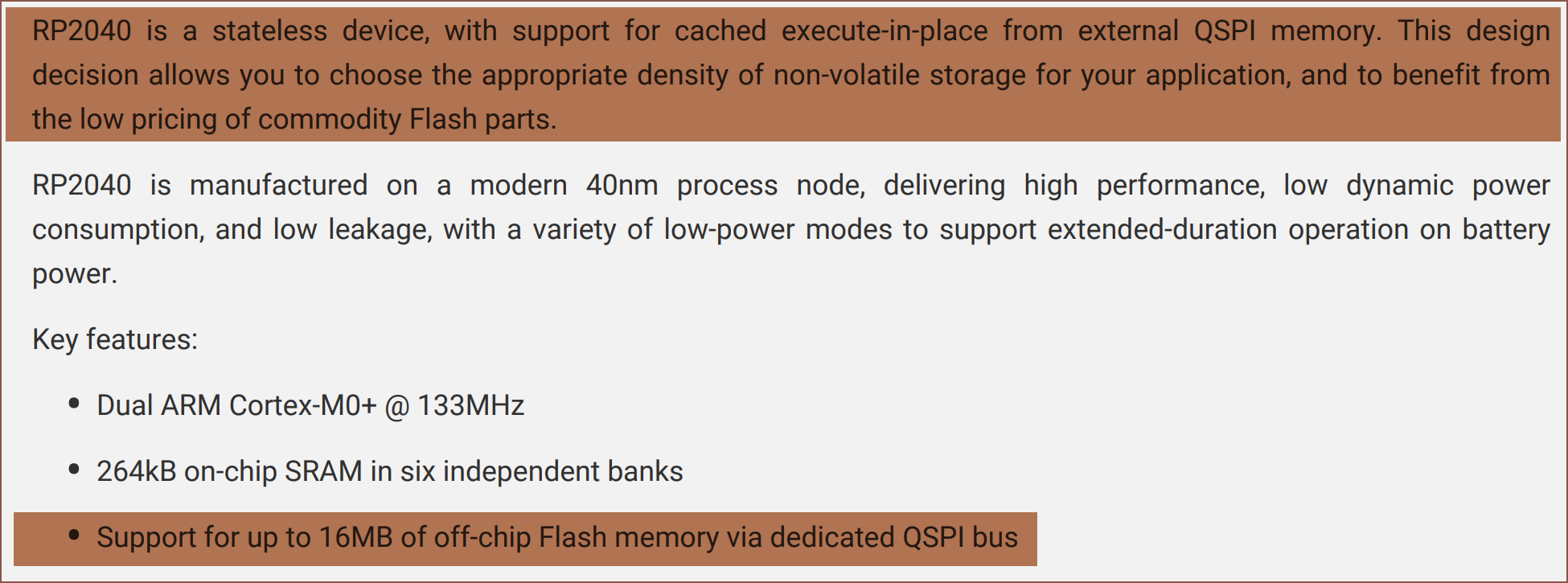
 Ahhhh mmmmnnn.
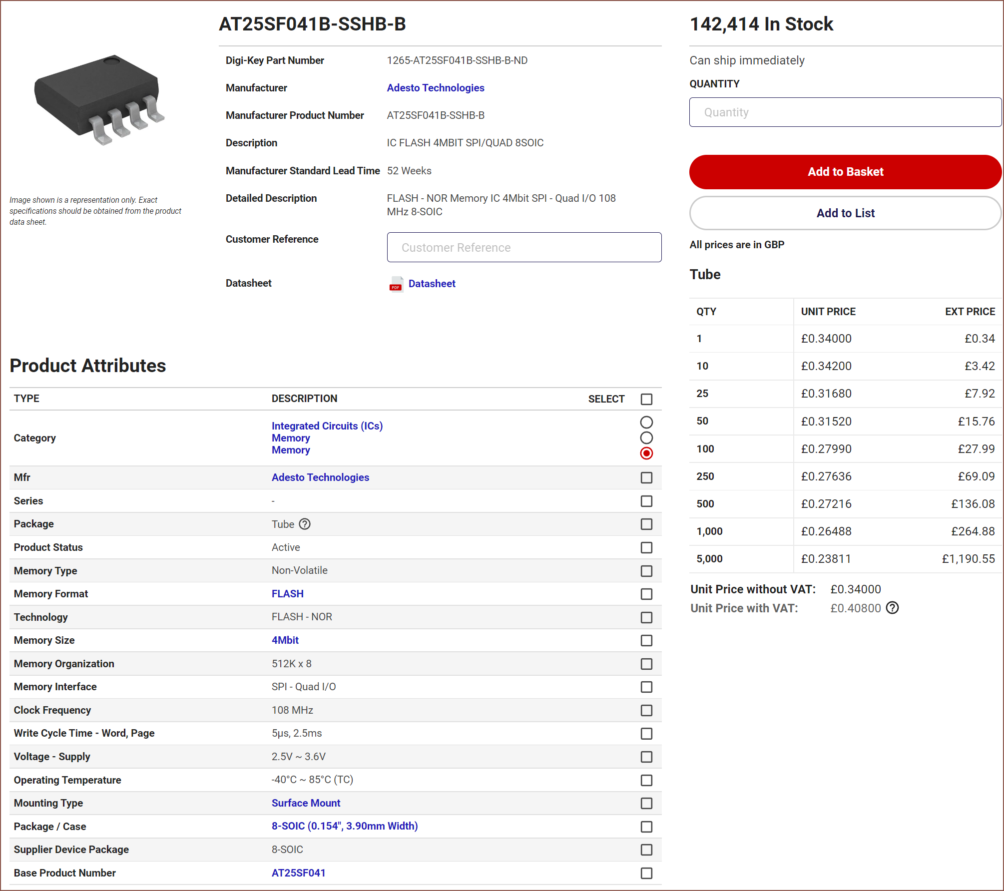 This looks like a good one. No idea why 10pcs costs slightly more than 1, but at 34p per each I'll look the other way.
That would put the total for the RP2040 at £1.14 for 256K of RAM and 512K of FLASH, which sounds decent actually. More than decent; isn't the RP2040 undercutting the entire (Digikey) market in almost every way in every metric other than available PCB surface area requirements???
If I can actually fit that 8-pin FLASH, then I could get access to a seemingly easy microcontroller to run Tetrinsic on. I'd have loads of memory, an entire core I could dedicate specifically for the screen, and likely a magnitude more internet documentation than Nuvoton's M032 line.
Conclusion + Concerns
It's looking more and more like mining a solution for a "Tetrinsic 2.0 even though 1.0 hasn't even happened yet" will bring forth a slew of benefits but be more expensive as a result. It's certainly a harder solution to mentally process, but the benefits would be:
- Higher quality material in contact with skin
- stainless steel instead of rubber
- Better aesthetic
- ball-chain looks more elegant and less mechanical/technical than a rubber belt
- potential option for LED or LCD backlighting
- Potentially cheaper PCB and easier to program microcontroller
- Potentailly less friction / resistance
- Smaller size
- Potentially better pressure sensitivity if I'm able to integrate a full-bridge load cell instead of the half-bridge solution I currently have.
The drawbacks would be:
- Potentially higher overall cost, especially factoring in the ball chain splicer
- Potentially noisier operation
- Potential for play in the ball-chain
- Higher build complexity
Things I'll have to further look into:
- Load cell space
- Available pins for RP2040 to see if I have enough and of the right kind.
- Amount of extra complexity in PWM controlling 5V LED when I have 3.3V logic.
- Thickness of 5mm LED strip
 kelvinA
 Load Cell Thoughts
Discussions
Become a Hackaday.io Member
Create an account to leave a comment. Already have an account? Log In.