So I started looking into the 595 IC once again, but it doesn't seem that I'd be able to send a PWM signal though it all that well. I decided to instead look into implementing the last thing (that I can remember, at least) which is the Memory In Pixel LCD from JDI.
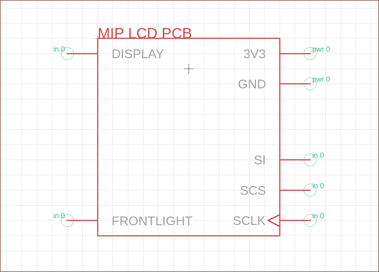
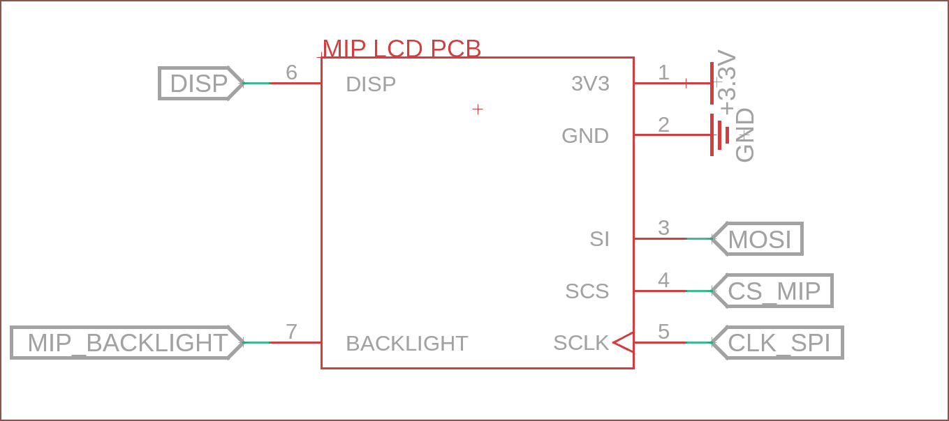
I was able to find this project which also includes the schematic for a breakout board. From the readme, I've created a symbol of the pins that I'd need to actually controll the board, and will put all the other components on a small PCB behind the display itself. Since I'd like to see if I can use a single 12P ribbon cable for all interconnects, an idea I've got is to also have the addressable RGB also connect via this LCD daughterboard (instead of having to make pad space on the main PCB). I'll see if that's a good strategy at a later time. For now though:

In the schematic, it looks like this:

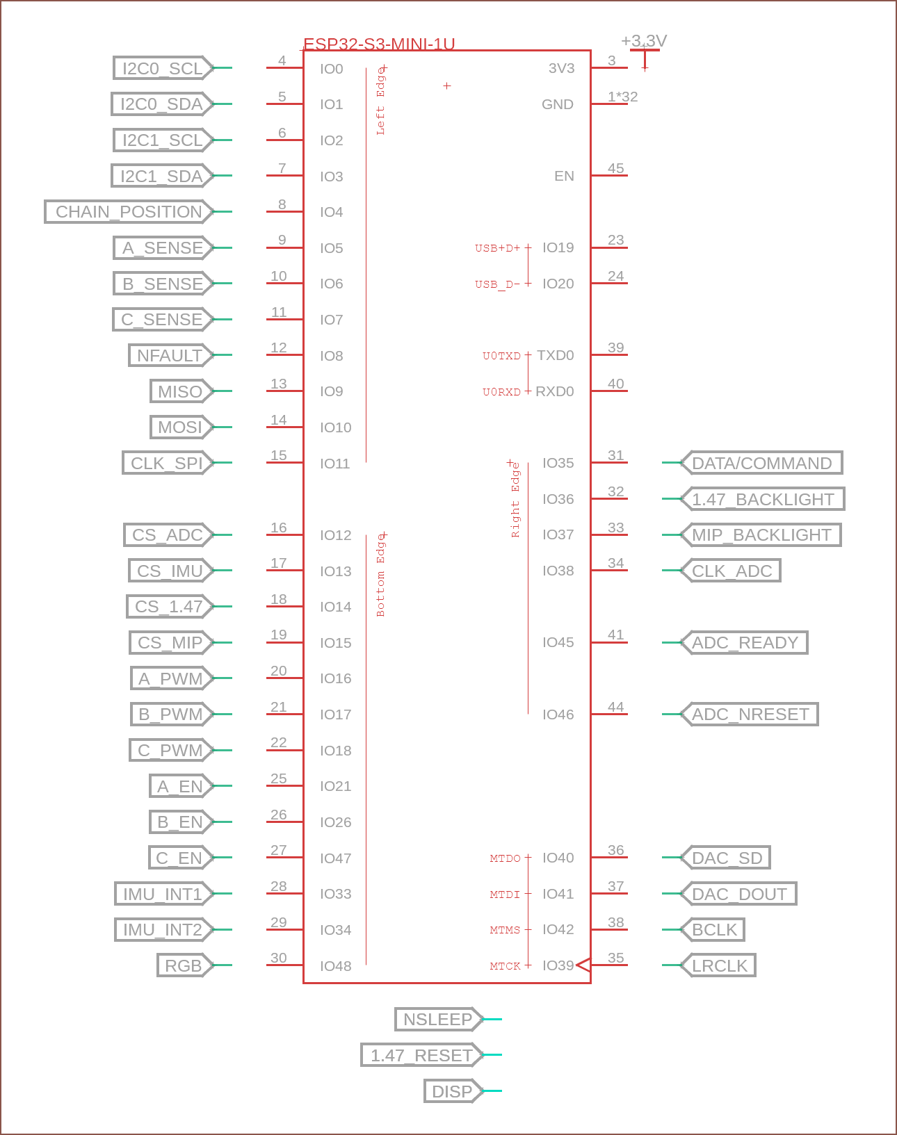
And that should be the last main component, so my pin utilisation looks like this:

Ouch... over by 3 pins. Ok... looks like I'm going to look into that 595 chip and see if I can get out of this.
 kelvinA
Discussions
Become a Hackaday.io Member
Create an account to leave a comment. Already have an account? Log In.