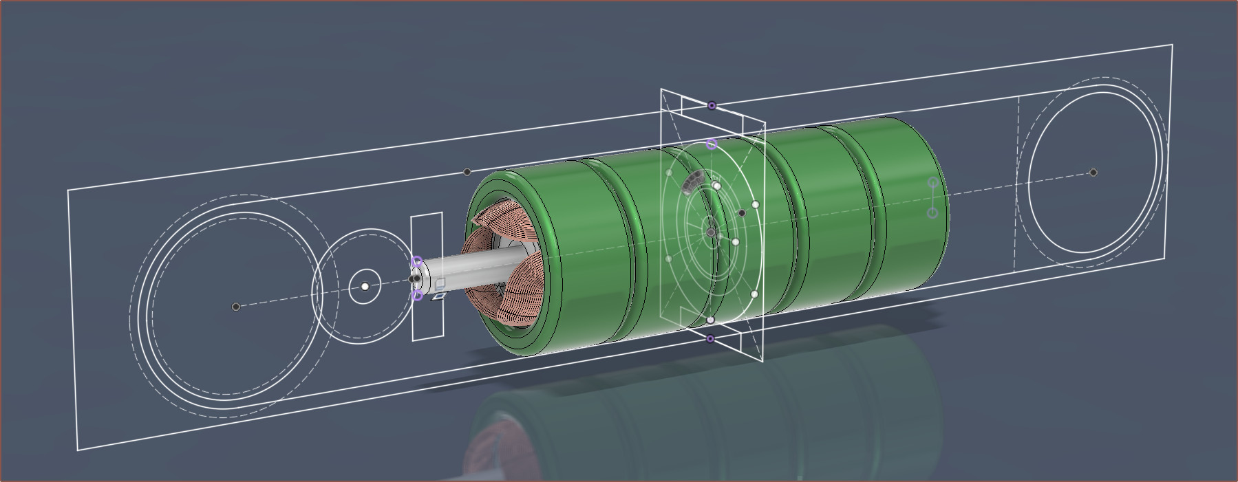
So this is the wireframe sketch of the proposed Tetrinsic strategy. The belt has just been approximated, but the actual belt path would go though both rectangles in the centre plane (which represent the cross section).

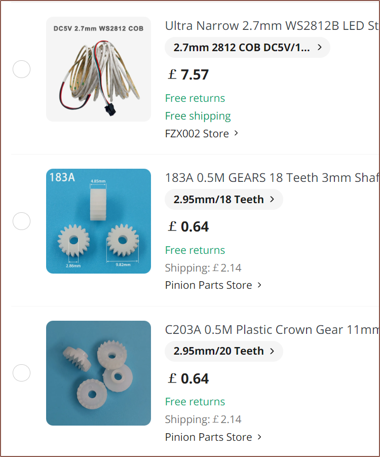
The plan is for the belt to roll on SLS printed, flanged 30T spur gears, and then connected to a crown gear (which I've never heard of until today) via an 18T gear. All gears are 0.5M.
Additionally, addressable LEDs exist in a 2.7mm COB strip which has 160 pixels per meter. The plan is to have one strip on each side of the belt. I'd consider this a "side-lit" approach.
I've been able to find an Alibaba supplier of a 4-pole, 50mm long, N35 magnet which is $7/ea for 10pcs, along with $64 UPS shipping to the United Kingdom. Thus, the magnet is about £12.30/ea after VAT. For now, I'm going to try the 2x40mm N42 magnet approach.
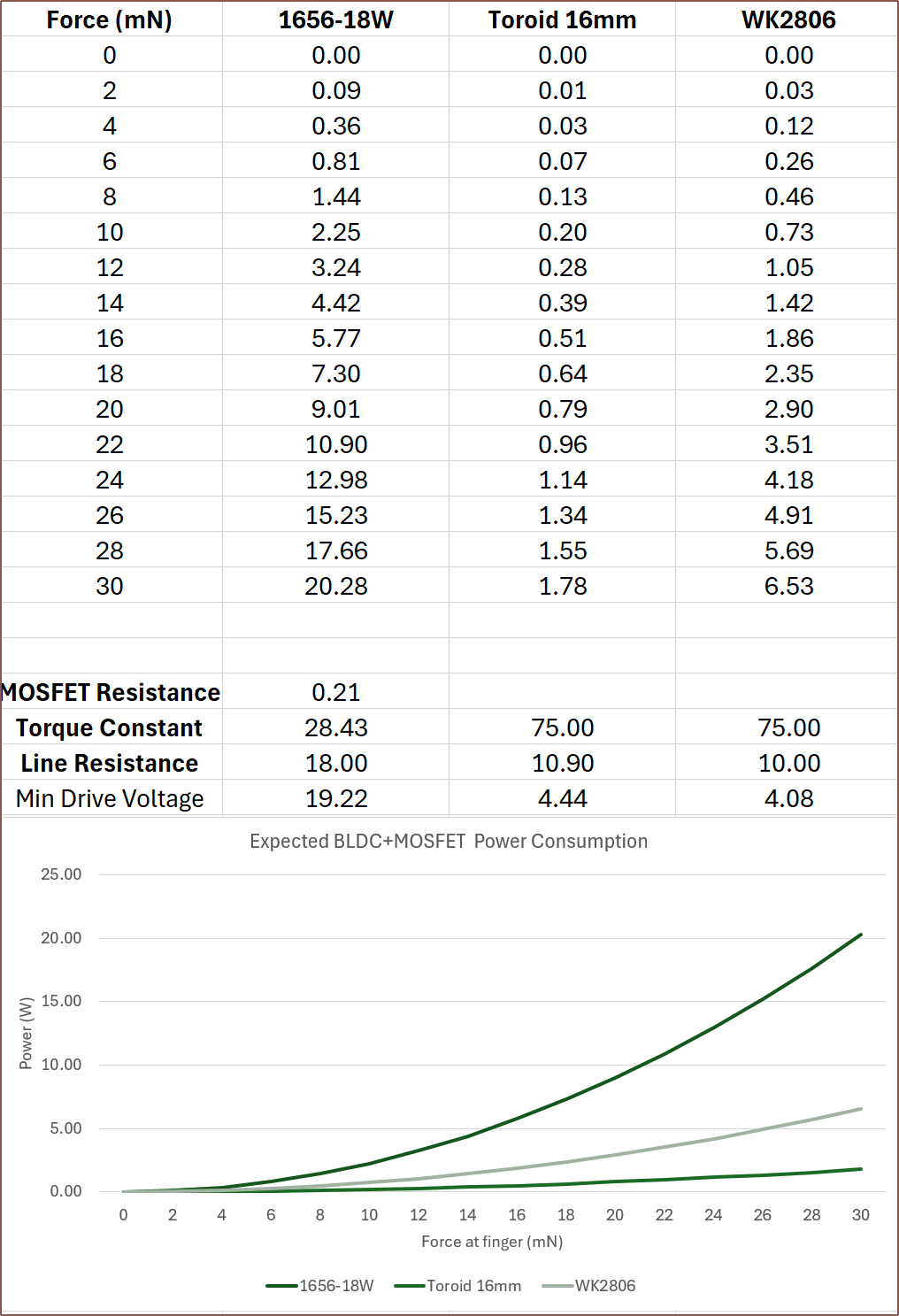
I also believe that I should be using the line / terminal resistance for calculating the minimum drive voltage and 0RPM wattages, as at least 2 coils will always need to be powered in a 3-wire BLDC to complete the circuit. The power numbers look steep but also more believable.

VMOT = 5V seems like a good value as the LEDs also need this voltage.
 kelvinA
Discussions
Become a Hackaday.io Member
Create an account to leave a comment. Already have an account? Log In.