I've just modelled the concept for the SuperSpindle and tweaked the Spindle (see below). The idea of the SuperSpindle is to be 3 tool positions wide so that the Slime's can rotate 90 degrees and a longer spindle can be used. While the effective head is 442mm long, There's still 558mm of travel on the X axis. I think the whole thing looks pretty cool.I fixed the Spindle file that broke when I decided to rotate the tool plates 180 degrees, got the spindle motor and ER16 collet from GrabCAD and inserted it into the file. I've also finally replaced the M3 square nuts (intended for the metal BMG extruder ages ago before I decided on creating the SecSavr Slight) with M3 bolts.
In other news, I asked BTT why there wasn't a listing for the M8P by itself, and it seems they've now added it on.
I do wonder if the STM32G0 is enough. Well the S6609's have interpolation so maybe running a few axes at 1/8 will still be ok, such as the Select, W or V axis. I still miss the old days when the OctPro was only £37, but other than the microcontroller's performance concerns, I can't see any reason to go OctPro instead of the M8P for my needs.
For the past 4 hours, I've been quickly modelling and this is where I've gotten to on the X Arm.
Tool Bar
Before going to the mini Z axis assembly in the X Slider, I wanted to look at modelling a concept Tool Bar.
I added the Selects and a few Slights to check alignment.
There's enough space for an 82mm tool and can be extended further if needed.
It seems that I can get 10 tools but not 12. I reduced the distance to 65mm and it still wasn't enough. This is when I realised that the implementation of the X Arm and V Axis could make or break getting 12 tools installed.
Ex Armu
(said with a Japanese accent, referring to the anime Ex-arm)
Started off by placing the components like this.I was wondering if I could use a 10mm ID pulley and then fix the ends with 8mm ID bearings, but the motor and pulley were too large for that idea. So I looked at how these are supposed to be installed and found the bottom set on Grabcad [Part 1, Part 2]and put it in the model.The magnet of an adjacent tool would clip it though, so I did some tweaks.Eventually, I had this. I took a page out of my time with the Anycubic Linear plus in that the carrige can extend a few millimetres past the end of the rail without issues. This is so that I could go down to a 100mm linear rail.I then had the idea to swap the sides of the ball screw assembly around so that I could get a face to screw in (top right) and a larger amount of free space for the V axis.
More space needed
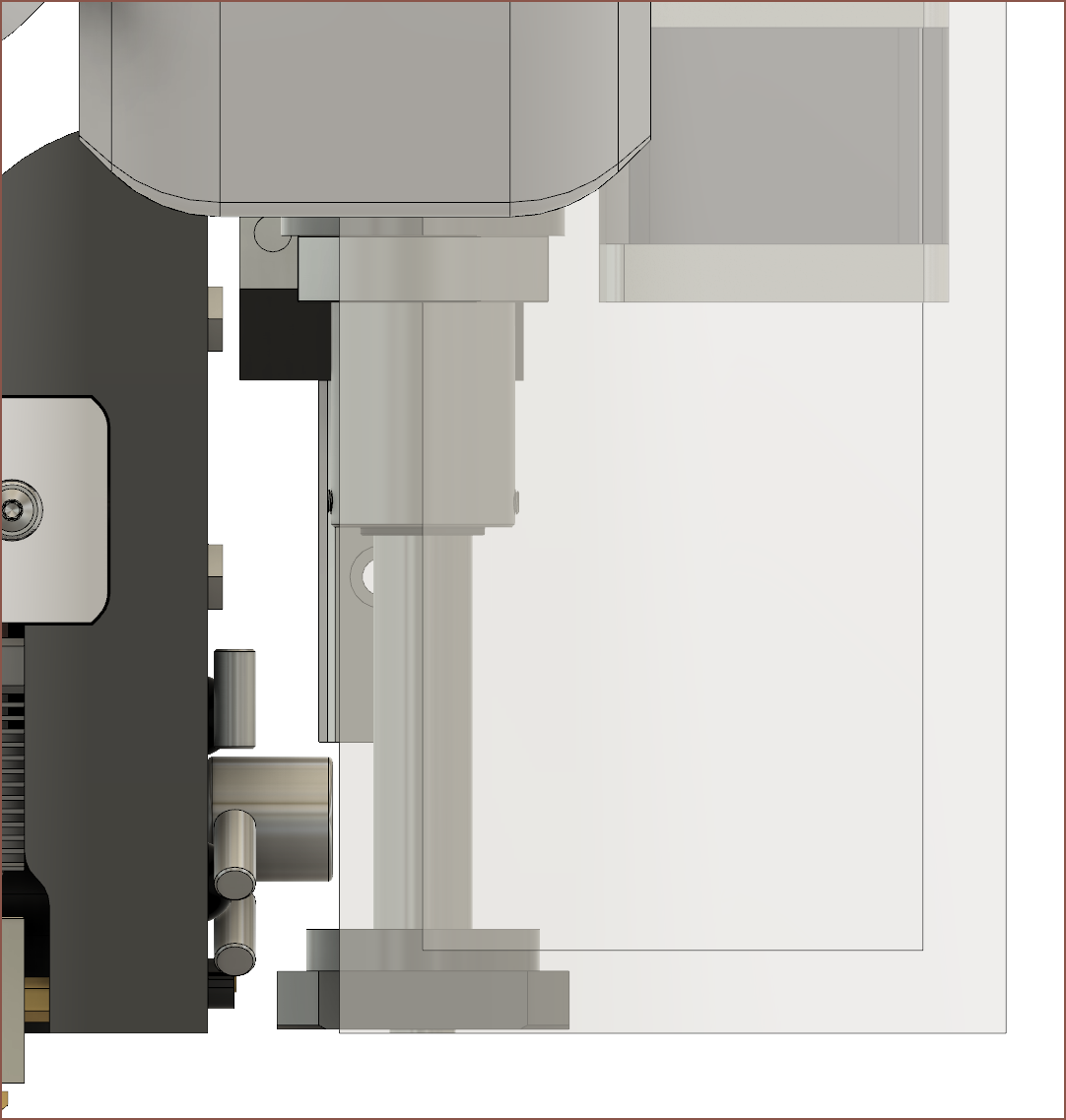
As you might be able to tell, the linear rail carrige is very close to the centre of the bearing, meaning that no shaft of any considerable size would be able to fit.
Some shuffling later and I got somewhere towards a better solution.
Some more refining and I got the above. I was able to go down to 140mm, which is 20mm shorter than where I started. I also brought the 150mm linear rail back for component stiffness.
V Axis
Now I need to figure out why multi axis CNC's need so much torque for rotational axes in the first place and then obtain a solution that fits in the space provided.
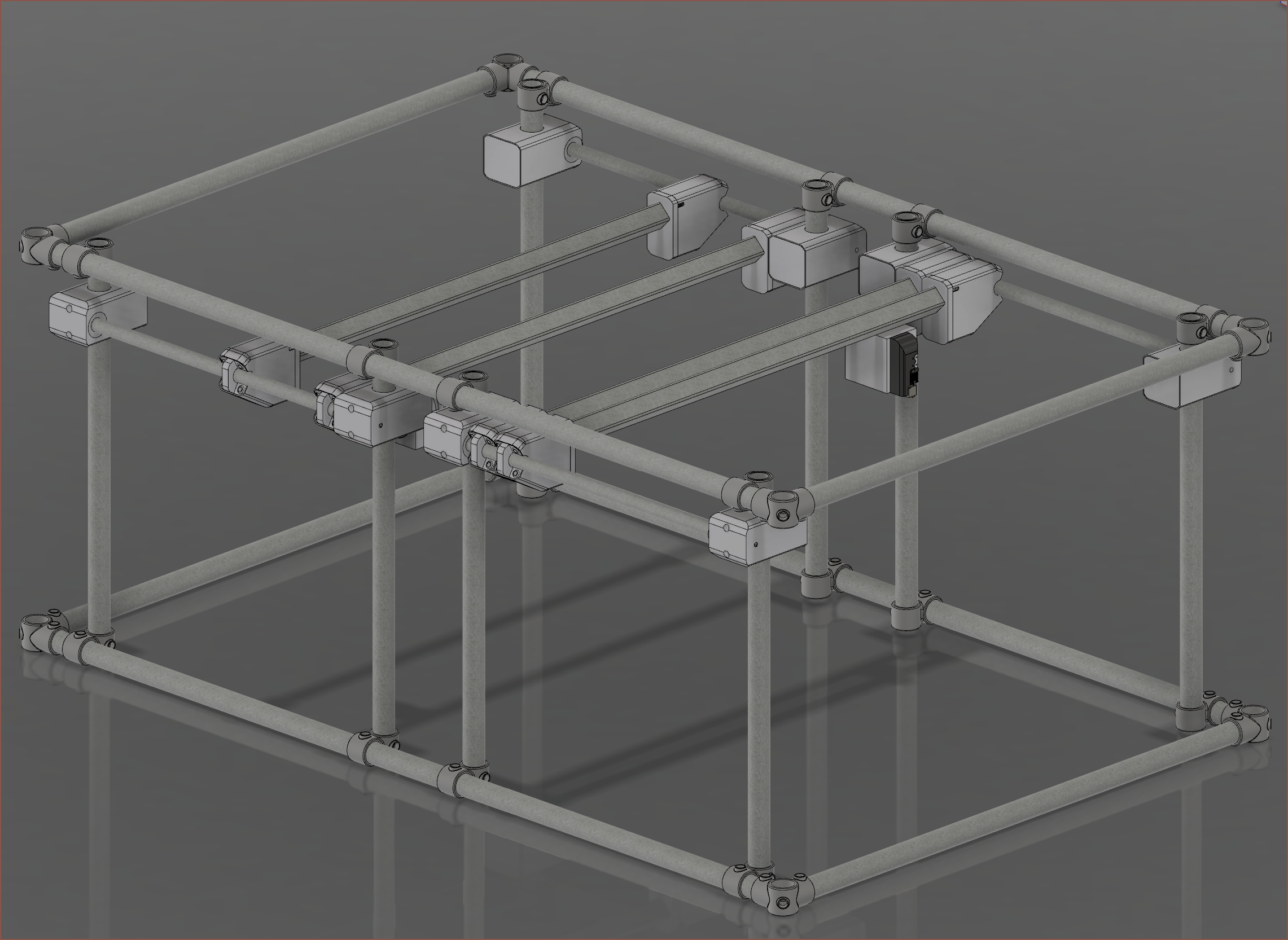
I've made the Y axis slider top and bottom faces of the cover symmetrical with the y axis tube. Not sure if it's added any visual appeal, but it has gained me 17mm of Z height. I now have an estimated 428mm from an 838mm distance from the bottom of the lower frame tubes to the top of the higher ones. This means I may achieve a 390x640x390mm build volume with the supervolcano melt extender.
I've also increased the distances of the Z beams from 750mm to 810mm now that the bowden tubes will be routed differently.
Now, I'm wondering if the 27mm tubes are the weakest link in this. It's still a wider diameter than what's used on the MPCNC (and probably has thicker walls) so I should probably try it before I deny it.
I'm wondering if I could have the X arm and slider be 1 part, and I got the idea to access the M8 nut cutouts from the side. This should also make it easier to dust as there's no deep top holes.
Next was the rail, and wow a HGR20 rail that's 150mm looks short.
It doesn't look like HGR20 is going to work all that well, so I swapped to HGR15.
Thought it was a good time to import the new slider into the main file and finally apply slider joints instead of rigids to the Slimes.
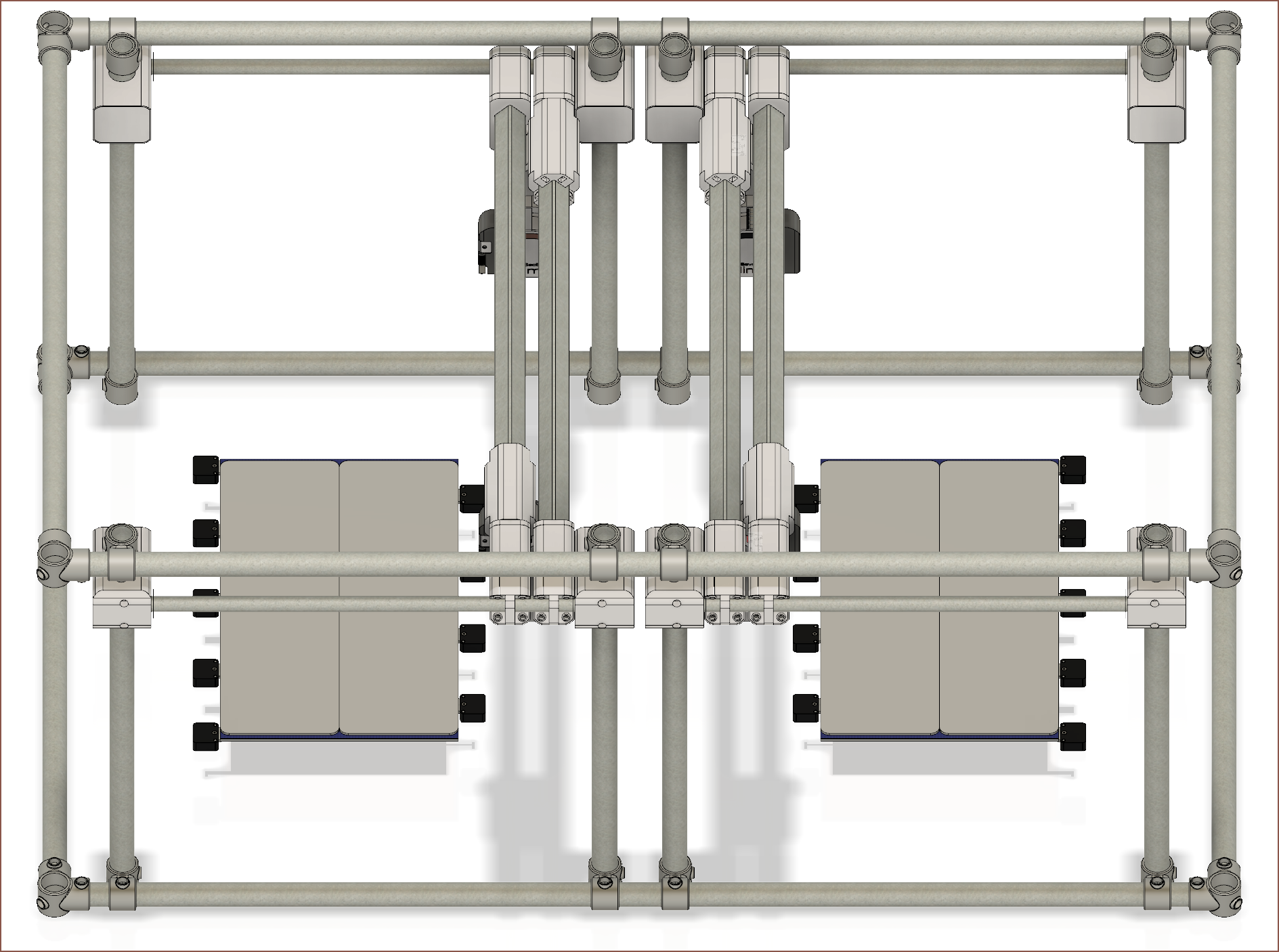
Now I can finally drag the heads around.What distance is that? Fusion: 200mm. Wait, if I play my cards right, I can get a solution I didn't think was possible because of the bowdens. No way. If I have the right Select connected to the left Slime (instead of left to left and right to right as I originally planned), a solution could exist.I'm not seeing any problems when taking Z into account either. This alteration would increase the independency of the IDEXY solution. For example, I could do mirror mode on the dual 65x20cm glass beds or access one more tool from the tool bar.The front Y axis would be able to get to the tool bar, but the Slime on the rear one will (probably) hit the bowden of the front Slime before reaching the tool bar.
My first guess for the length of the slider was 160mm and it looks to be a good one. I first tried going around, but that looked to take up too much X space, so I rearranged it:Now looking at it again, I could rotate the slider 90 degrees. Next I tried a couple designs but reverted on the ideas.Then I added the temporary arm idea, making sure that it wouldn't hit any adjacent tools when moving moving to the Tool Bar. I decided to do the Tool Bar after this because I had a feeling that I was going to have to move the Slime's down to accomodate the 150mm HGR20 and ballscrew for the mini Z axis, and that's looking to be the case. I might opt for 2 MGN15's instead; it depends on how everything fits in the arm, but 2 MGN's are more expensive than 1 HGR20 by a tad, not to mention having to make sure 2 rails per Slime are aligned would likely complexify assembly and maintenance.
Good thing that I found that 35cm glass because it looks like I'd actually be able to use most of the circular diameter. I'm planning on having the bed rotate so that it can reach the entire area.Unexpectedly, it looks like I might actually be able to get both Slimes to reach over the length of the Long Bed.
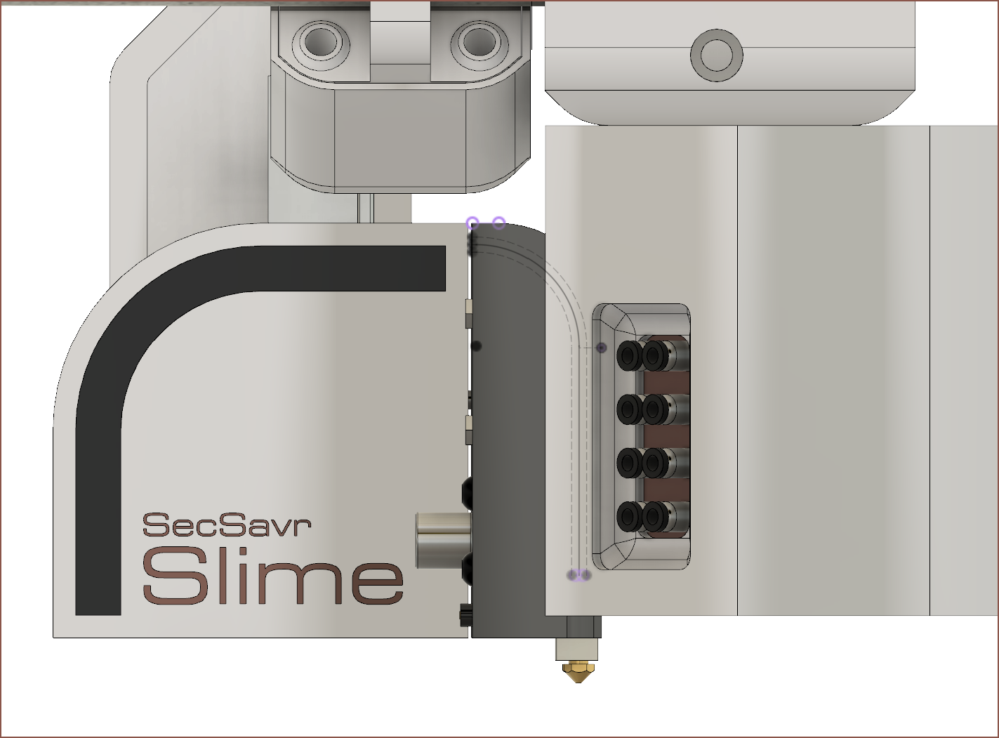
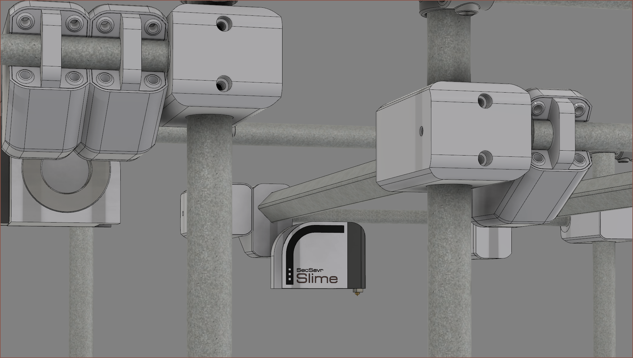
As I was staring at the gantries inside the SleepCinema, I had an idea for the way I'm going to do the Slime branding.
The idea is to have the left Slime as one colour and the right as a different one. I'm thinking a different colour for the text looks better:
I originally wasn't so keen on this new Slime shape that was needed for the camera, but I'm liking this design change now.
Then I thought "Slime" reminded me of the word "sublime" and went to look at the definition.Looking at those adjective definitions, that sounds quite a lot like this SecSavr to me, so it's a possible option.
Anyway, I also wanted to see what adding 3 dots would look like:
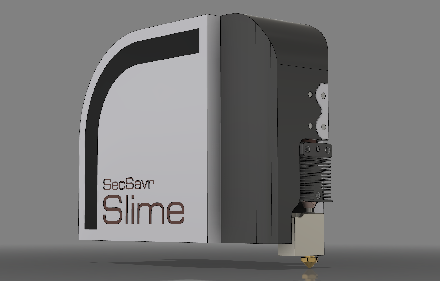
I think the dots tie together the overall brand (see my logo) and give a bit more of a technical vibe (like some Asus laptops [below]) but I do also like the uninterrupted line too.I've done the other side and those 3 dots certainly do add a bit of an "advanced tech" look.However, in the SleepCinema, the 3 dots look a bit extra:So I'm going to opt out of the dots.
I've just extended the second part of the clamp for the Z axis slider to create a cover that matches the Y axis.The SecSavr's looking somewhat "sleeper PC" now, but that just means that the design is calming and looking closer to a consumer appliance than DIY or industrial machinery.
Now I actually imagined that this slider would look a bit differently. I was thinking that I was going to have some additional fin that had a steeper angle than just extending the side curve for the bottom cover section. I also didn't originally have the top cover part in mind, and the white extrusion at the right of the image was invisioned to be a large bracket. Now that I mention it, I feel like there's a sketch I drew in a log somewhere.
These changes are due to the tubing I'm switching to coming in specific sizes. The Metal Store will still cut them to length if needed, but I assume that if I needed 1.1m, I'd have to pay for a 2m length.
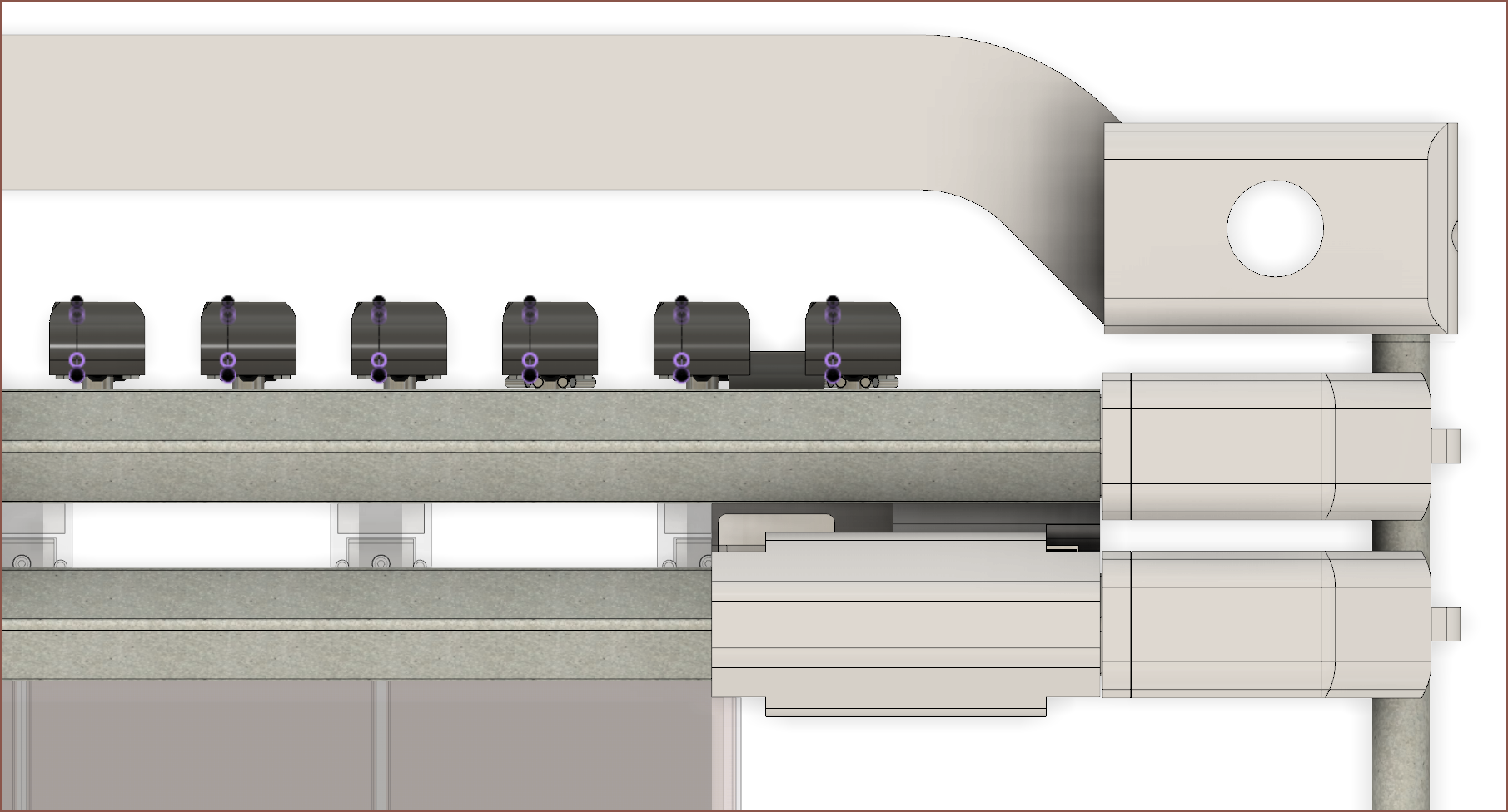
Looking at the CAD, I actually need the entire 1m span to be rollable so that both Slimes can still reach the full 500mm length of the default 3 axis bed. Thus, I'm going to see if I can hold the tube from the inside. This also means that I can move the X/Y motors so that the outer enclosure looks seamless. I plan to use the same overal slider for both sides, so that's why the motors are overlapping in the top image.
[E1] Finishing the cover and finding an alternative supplier
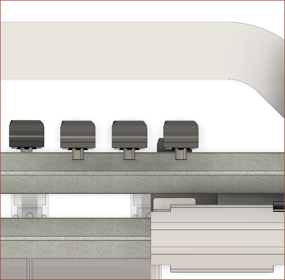
Now this looks more solid and professional. I've got to go back though and rotate the X axis motor 180 degrees so that the X axis belt is as close to the beam as possible. Additionally, I stumbled on another box section supplier and they're much more flexible.Thicker, longer and cheaper box section? Yes please.
But yeah there goes my lovely continuous cover idea.
[E2] New X axis motor location
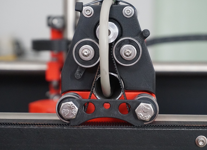
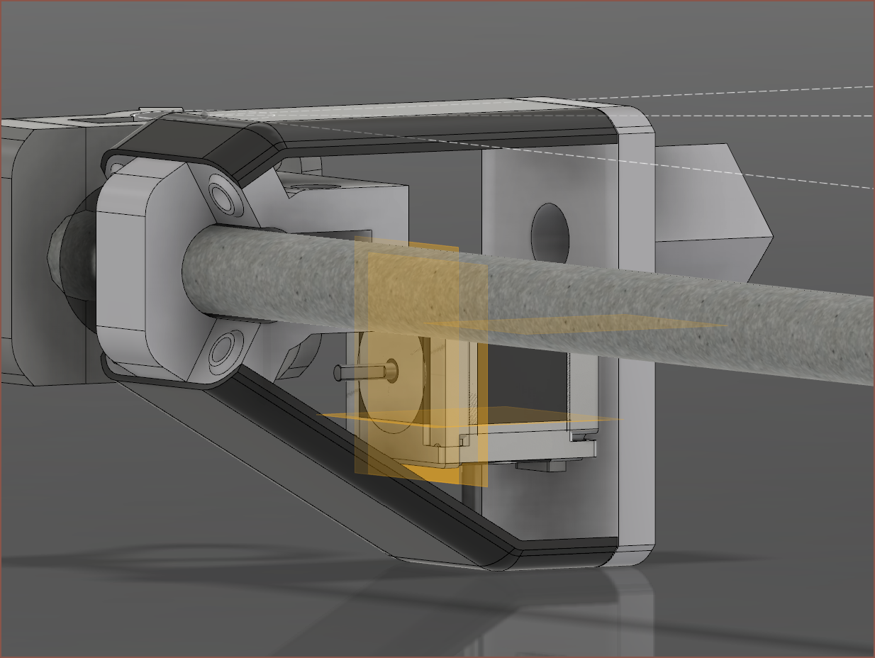
I think that worked out nicely actually. There's a 17mm cutout for the 15mm belt that you can see just after the white block part on the left. As this printer is being designed with CNC milling in mind, they're planned to be dual 15mm 3M belts that interlock like a zipper to hopefully have the same stiffness as a 30mm wide belt. It's an idea inspired from this MPCNC upgrade.
 kelvinA
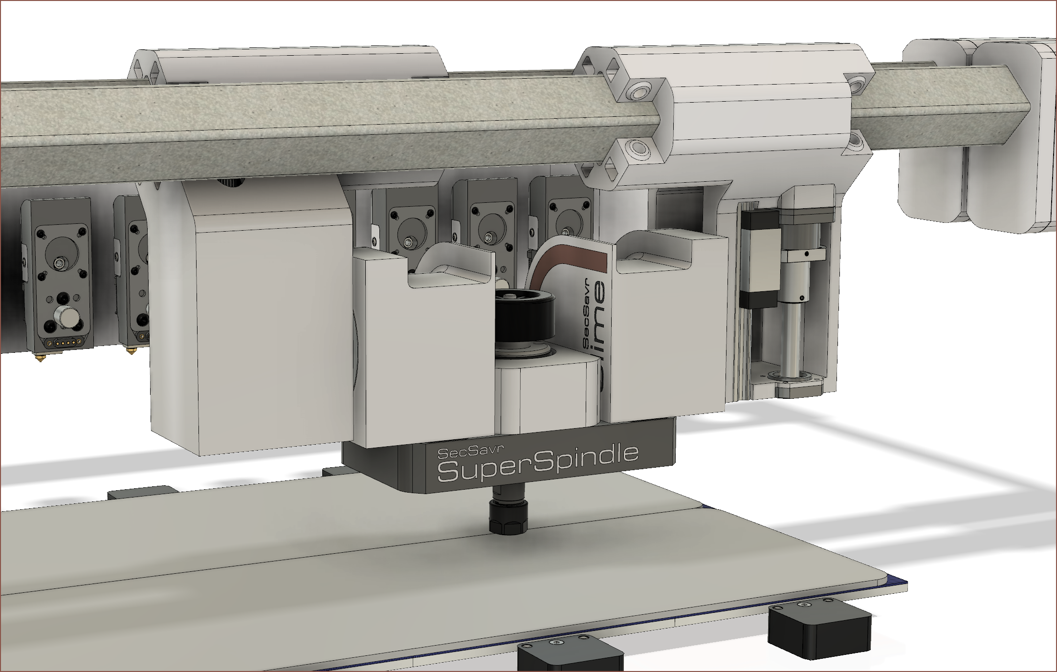 I've just modelled the concept for the SuperSpindle and tweaked the Spindle (see below). The idea of the SuperSpindle is to be 3 tool positions wide so that the Slime's can rotate 90 degrees and a longer spindle can be used. While the effective head is 442mm long, There's still 558mm of travel on the X axis. I think the whole thing looks pretty cool.
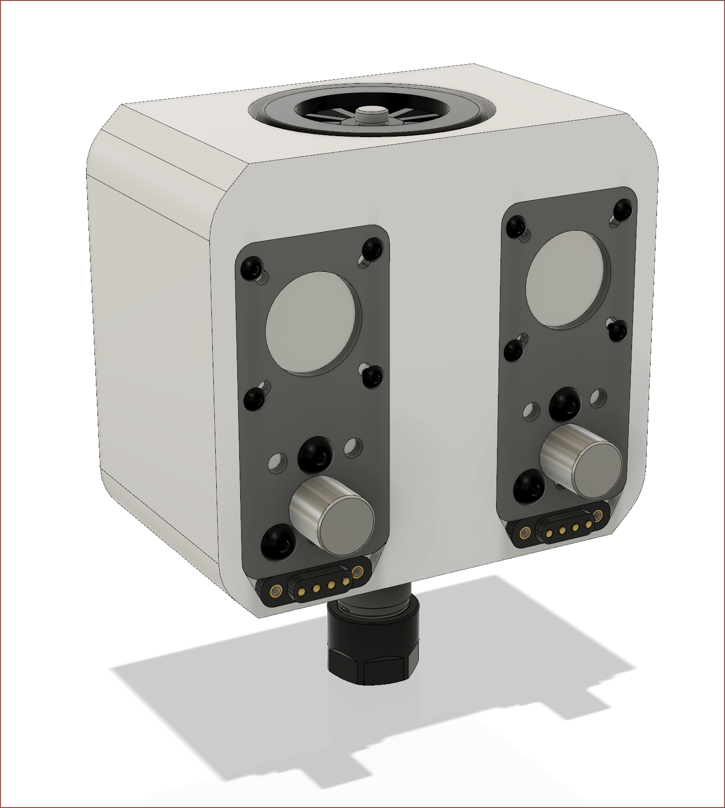 I fixed the Spindle file that broke when I decided to rotate the tool plates 180 degrees, got the
 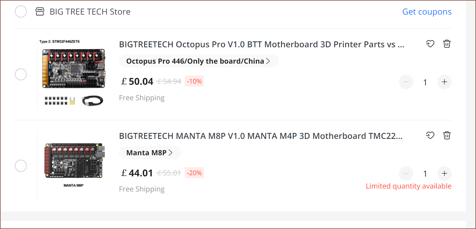 I do wonder if the STM32G0 is enough. Well the S6609's have interpolation so maybe running a few axes at 1/8 will still be ok, such as the Select, W or V axis. I still miss the old days when the OctPro was only £37, but other than the microcontroller's performance concerns, I can't see any reason to go OctPro instead of the M8P for my needs.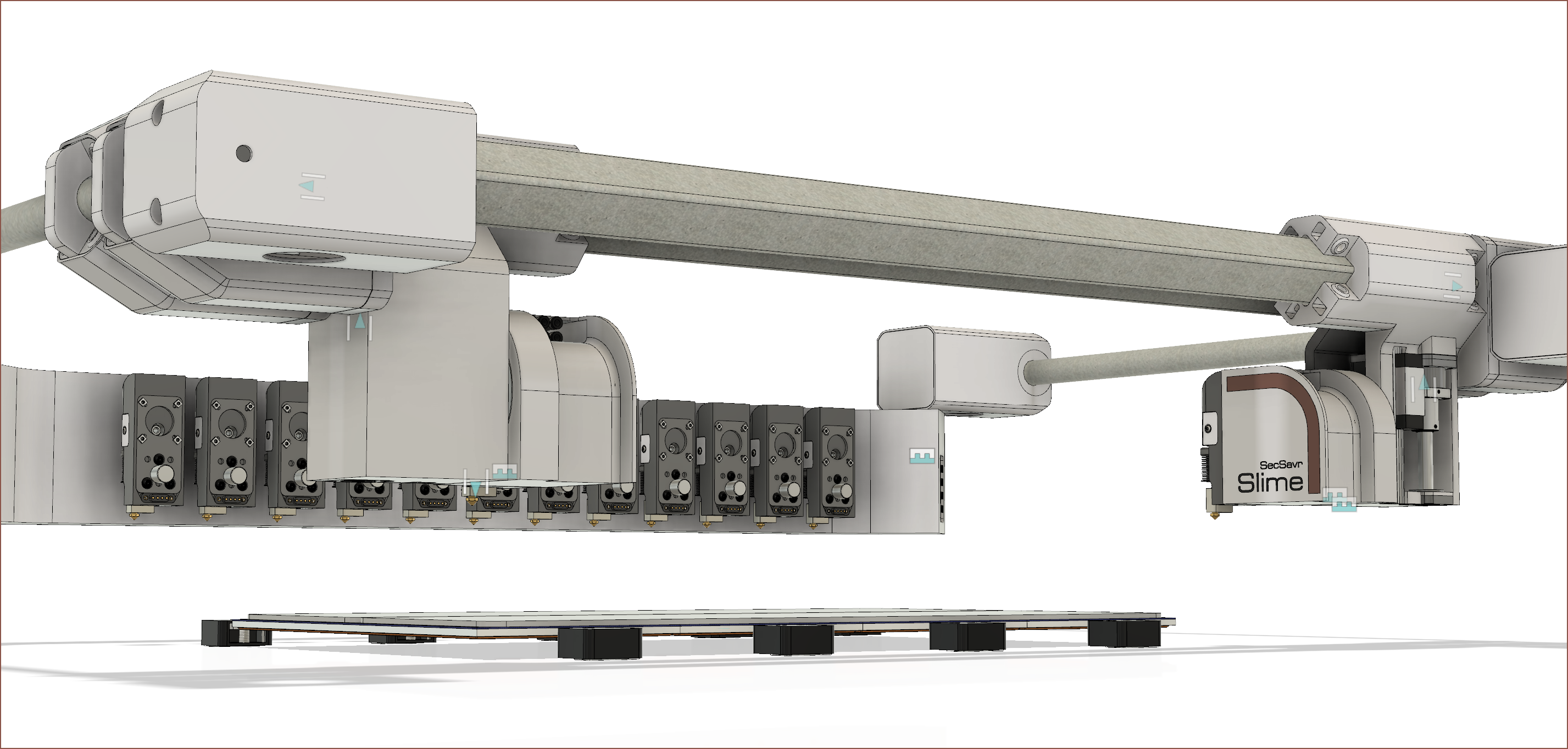

 It seems that I can get 10 tools but not 12.
  I reduced the distance to 65mm and it still wasn't enough. This is when I realised that the implementation of the X Arm and V Axis could make or break getting 12 tools installed.
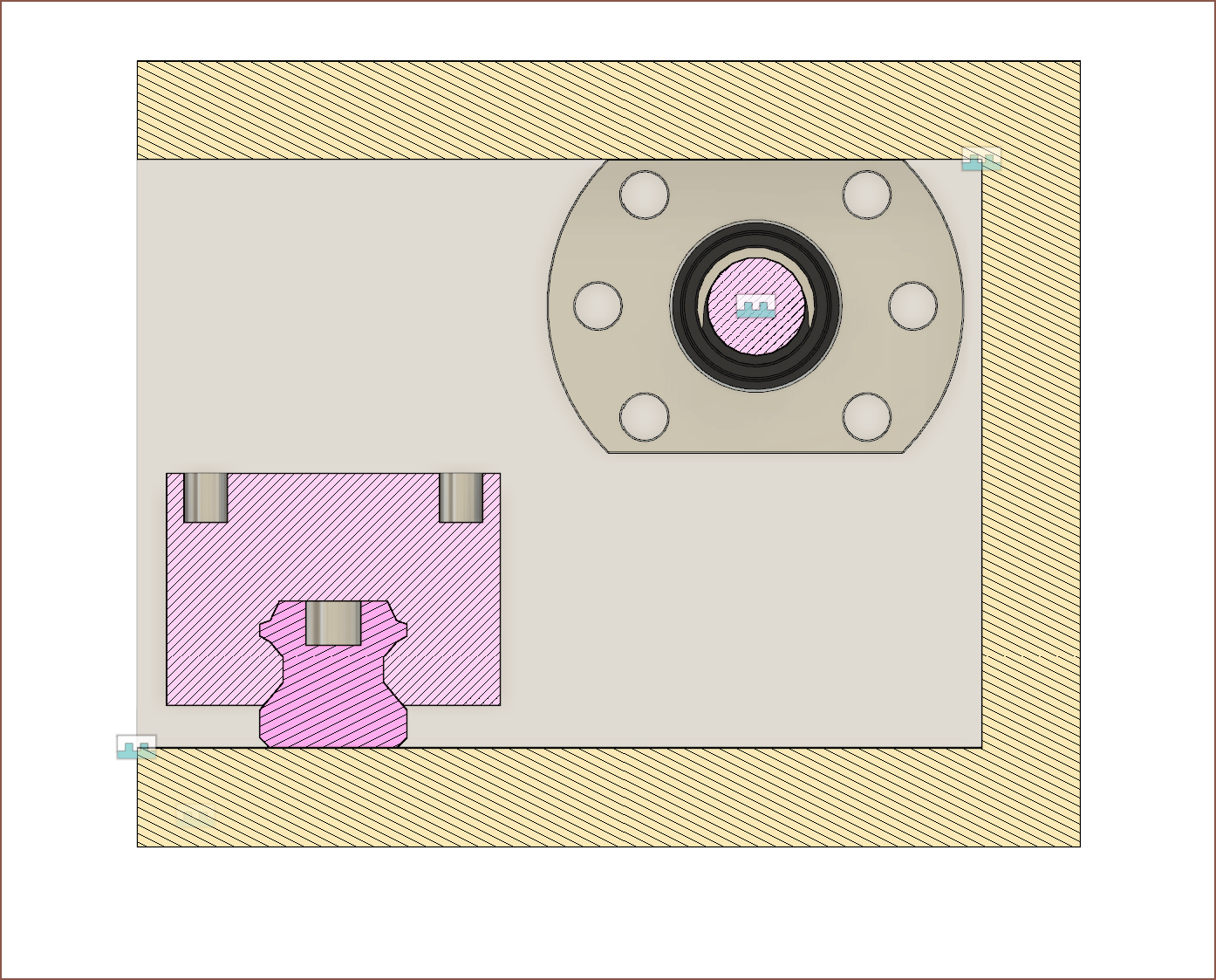 Started off by placing the components like this.
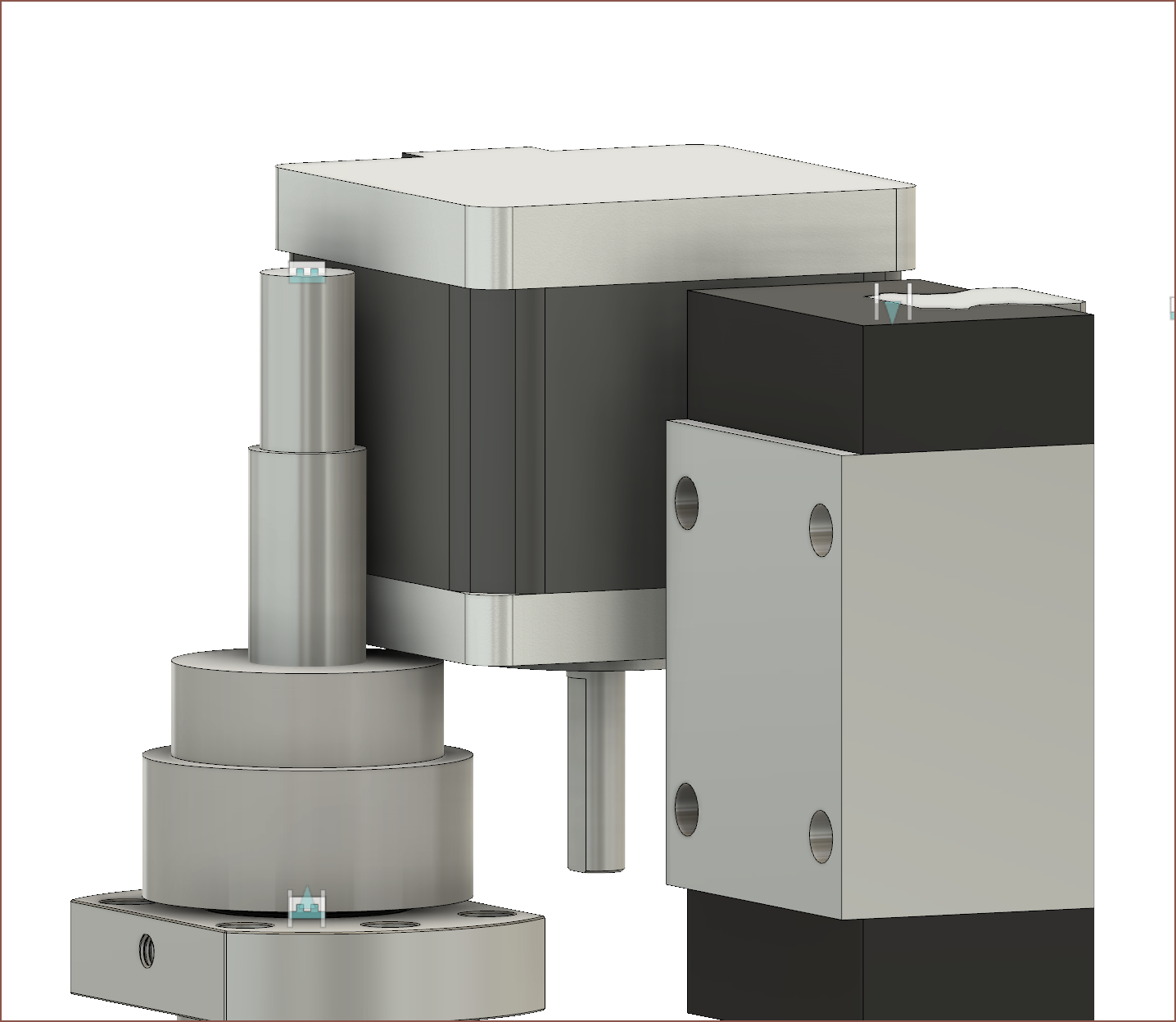 I was wondering if I could use a 10mm ID pulley and then fix the ends with 8mm ID bearings, but the motor and pulley were too large for that idea. So I looked at how these are supposed to be installed and found the bottom set on Grabcad [
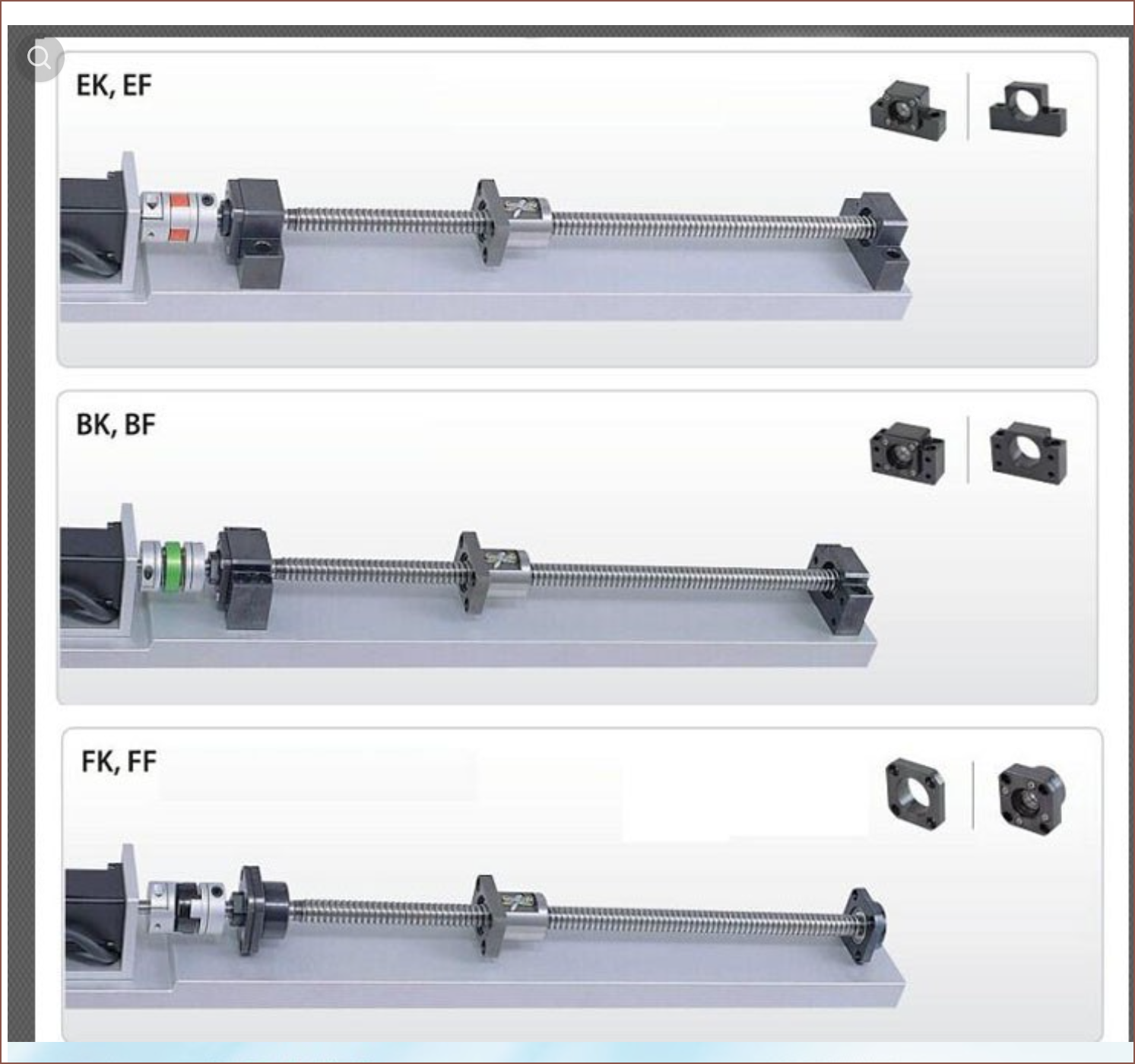 and put it in the model.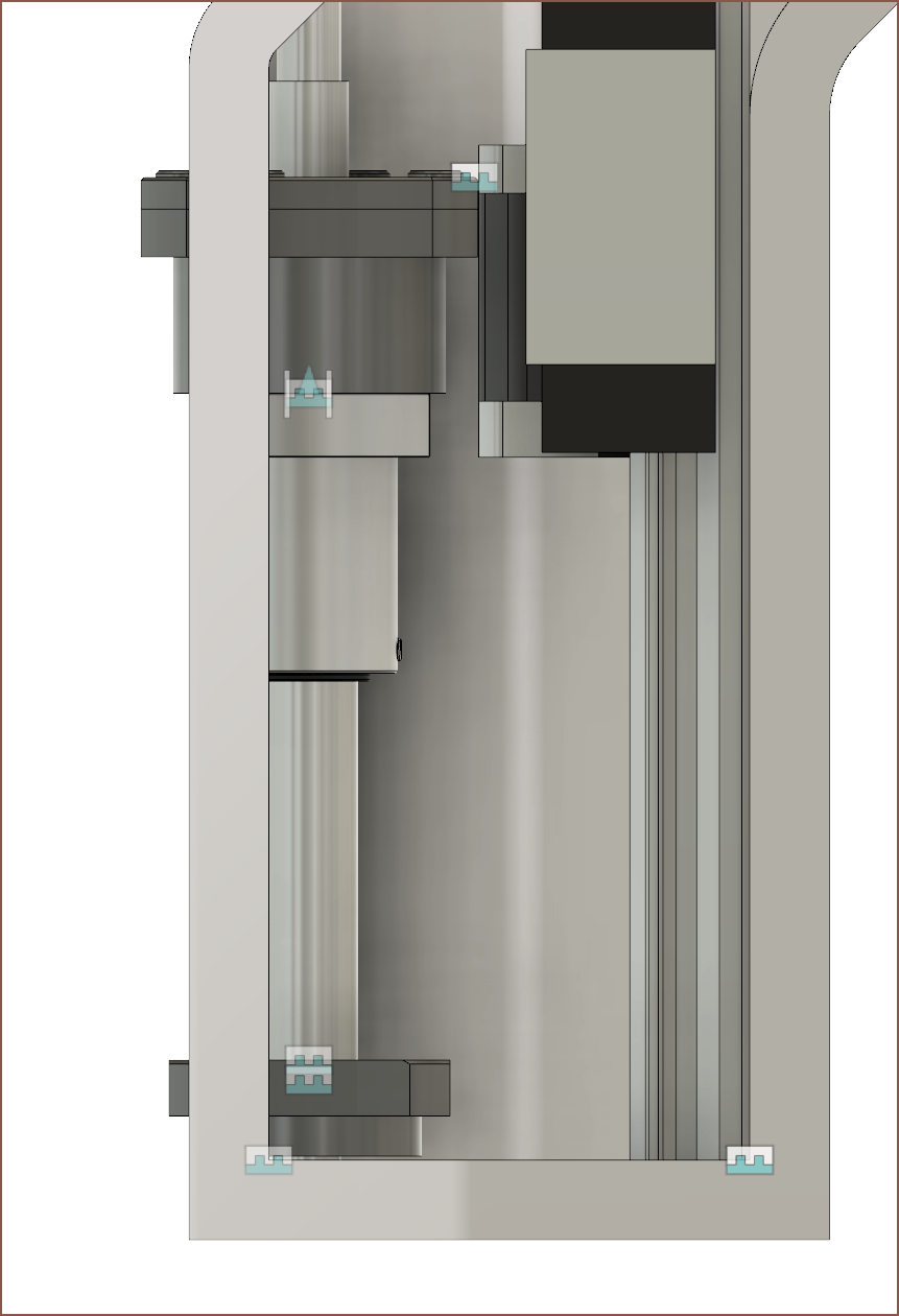
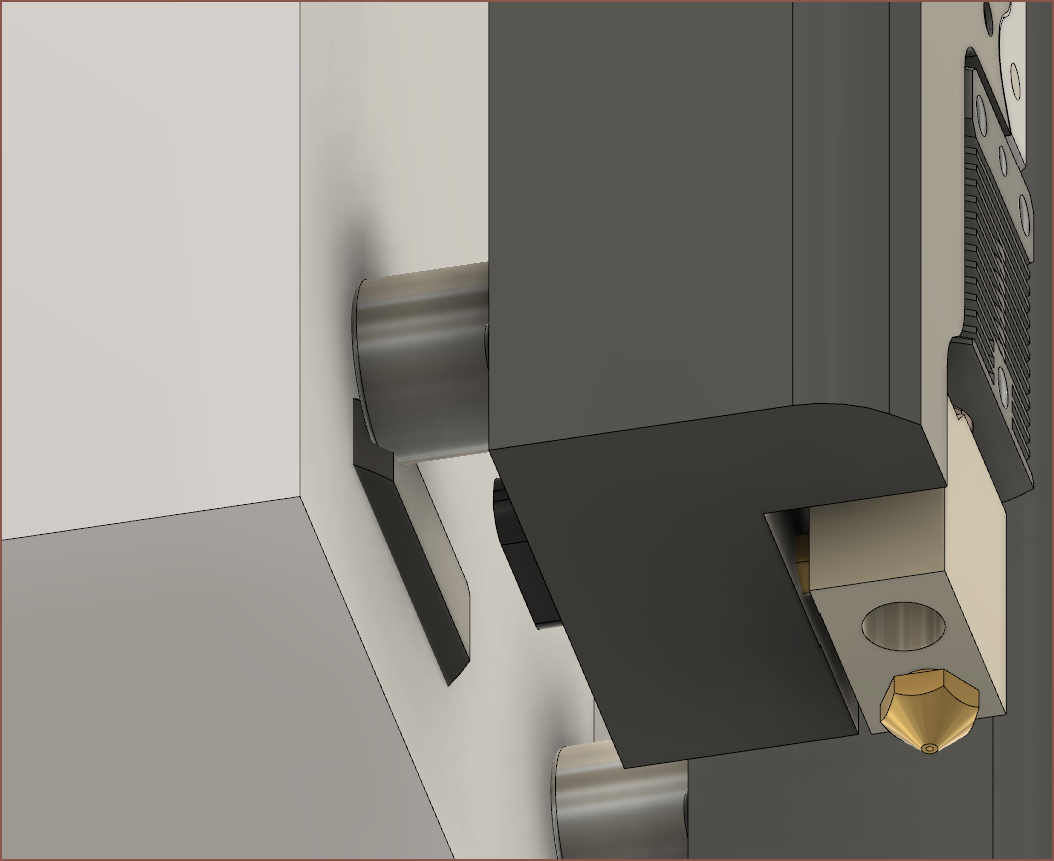 The magnet of an adjacent tool would clip it though, so I did some tweaks.
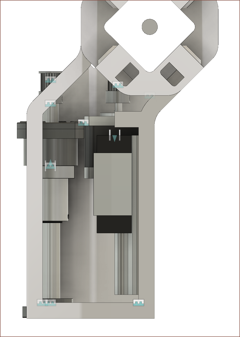 Eventually, I had this. I took a page out of my time with the Anycubic Linear plus in that the carrige can extend a few millimetres past the end of the rail without issues. This is so that I could go down to a 100mm linear rail.
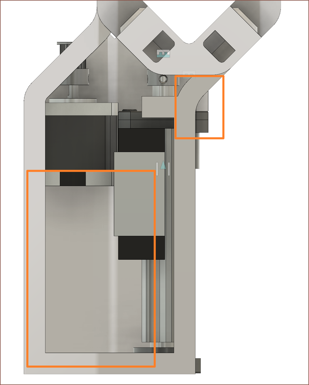 I then had the idea to swap the sides of the ball screw assembly around so that I could get a face to screw in (top right) and a larger amount of free space for the V axis.
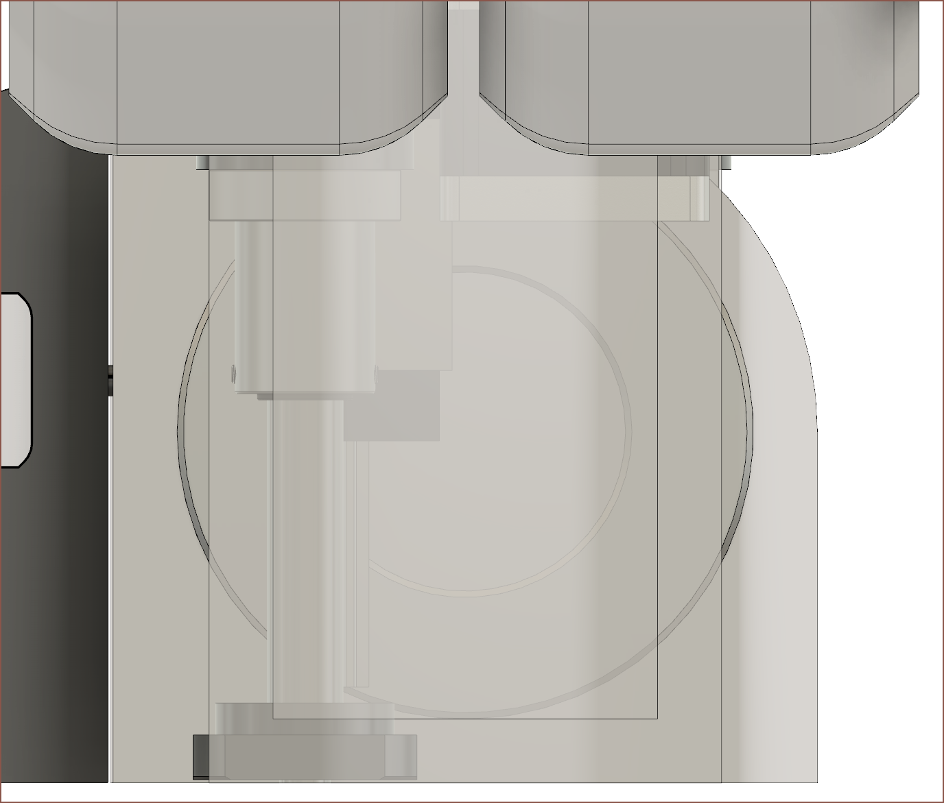 As you might be able to tell, the linear rail carrige is very close to the centre of the bearing, meaning that no shaft of any considerable size would be able to fit.
 Some shuffling later and I got somewhere towards a better solution.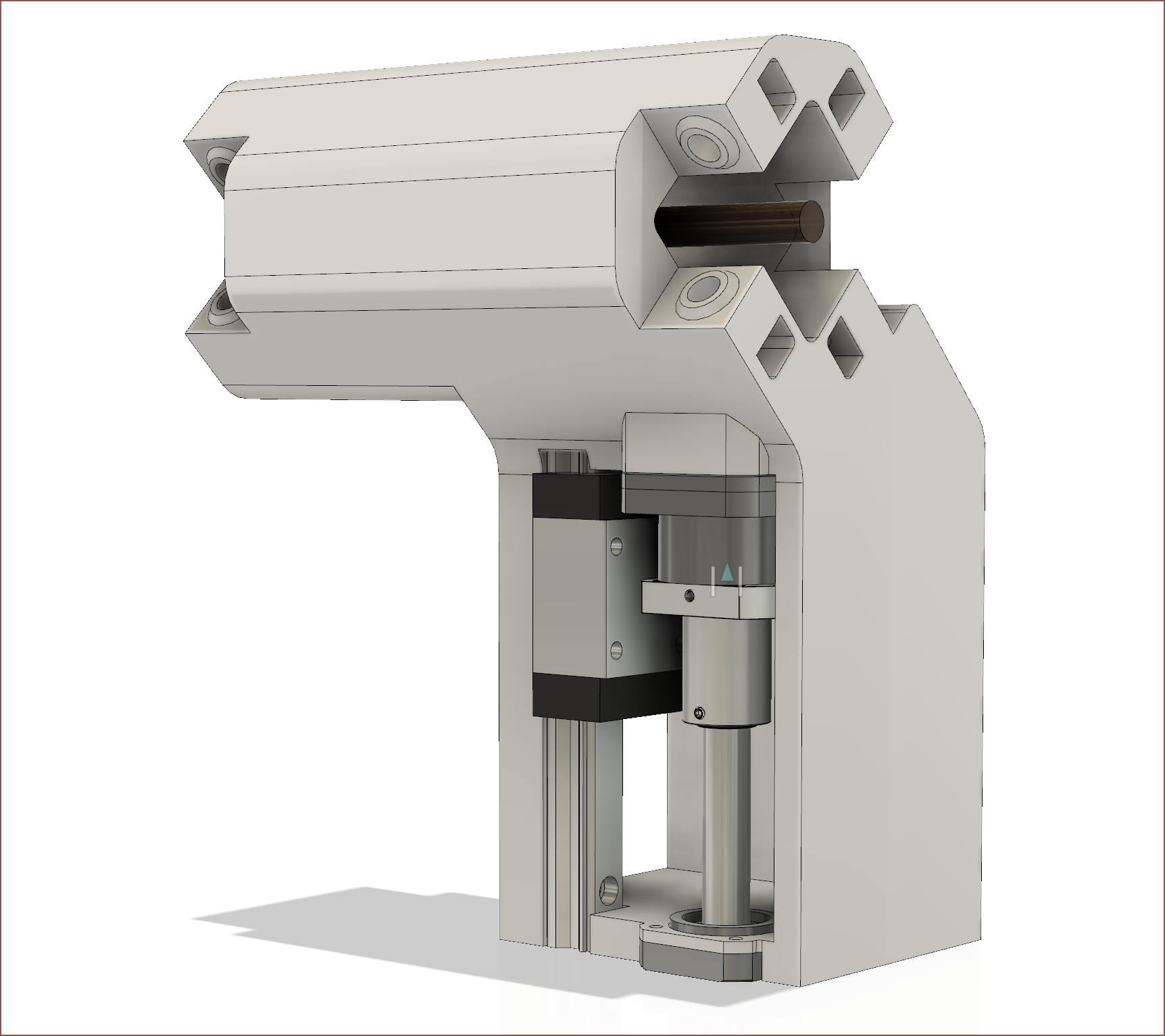
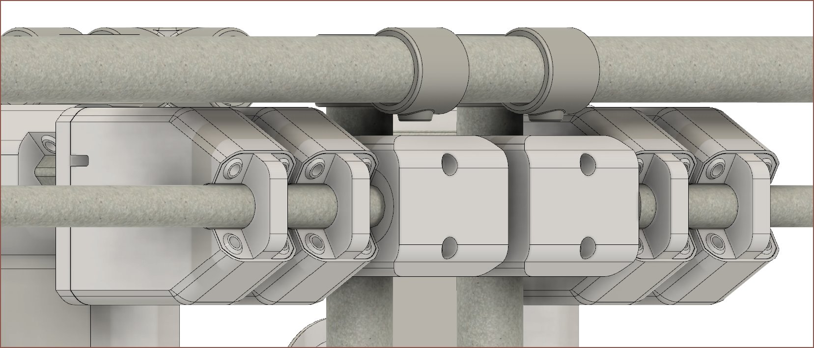 I've made the Y axis slider top and bottom faces of the cover symmetrical with the y axis tube. Not sure if it's added any visual appeal, but it has gained me 17mm of Z height. I now have an estimated 428mm from an 838mm distance from the bottom of the lower frame tubes to the top of the higher ones. This means I may achieve a 390x640x390mm build volume with the supervolcano melt extender.
 Now, I'm wondering if the 27mm tubes are the weakest link in this. It's still a wider diameter than what's used on the MPCNC (and probably has thicker walls) so I should probably try it before I deny it.
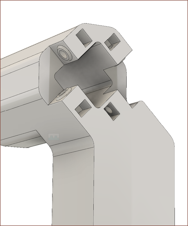 I'm wondering if I could have the X arm and slider be 1 part, and I got the idea to access the M8 nut cutouts from the side. This should also make it easier to dust as there's no deep top holes.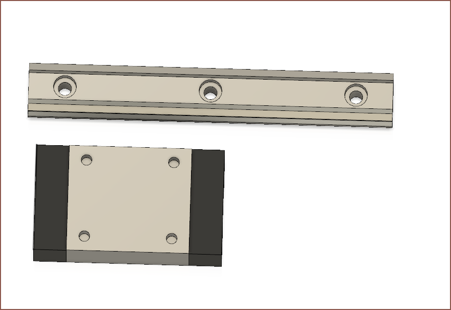
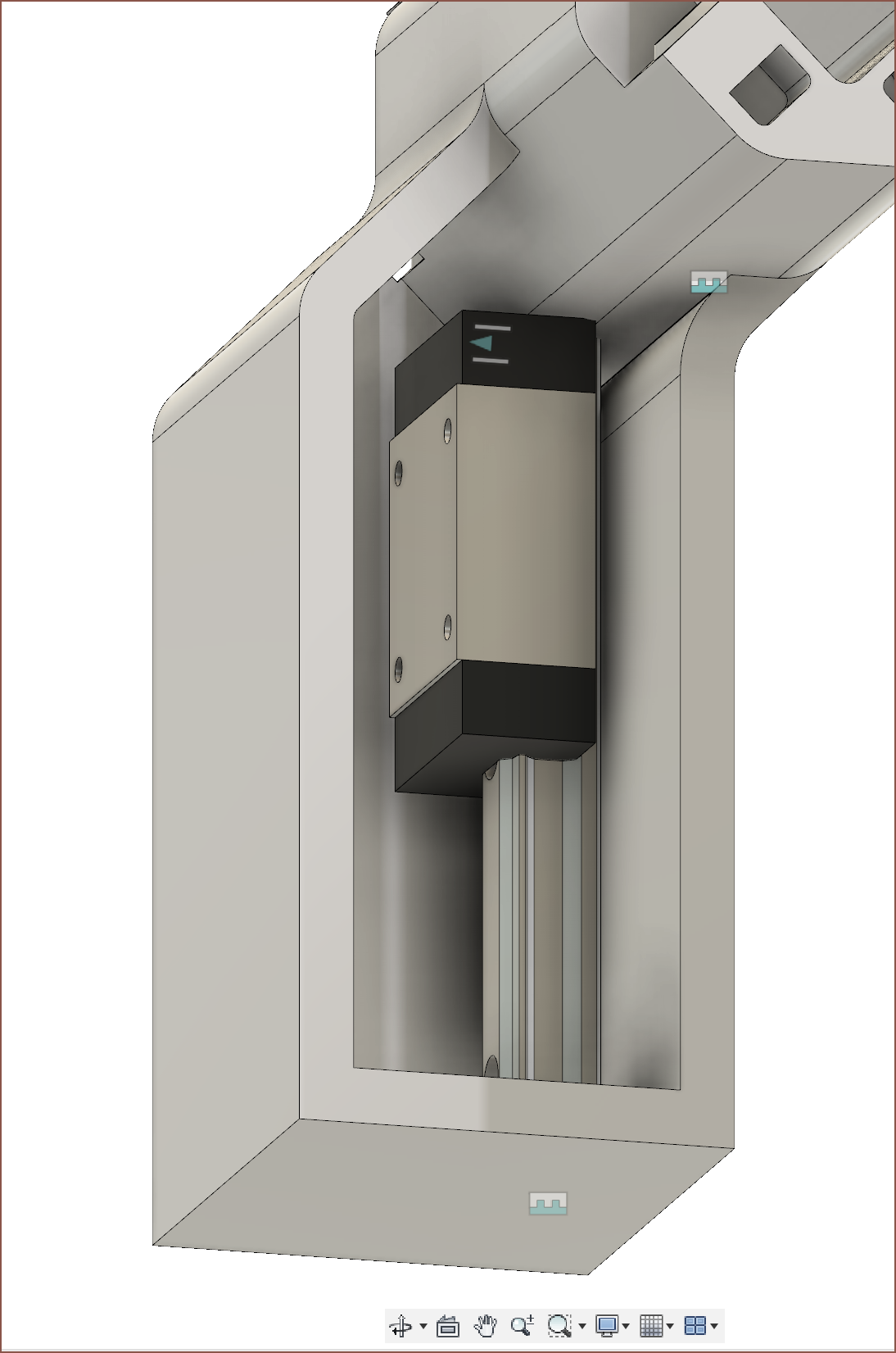
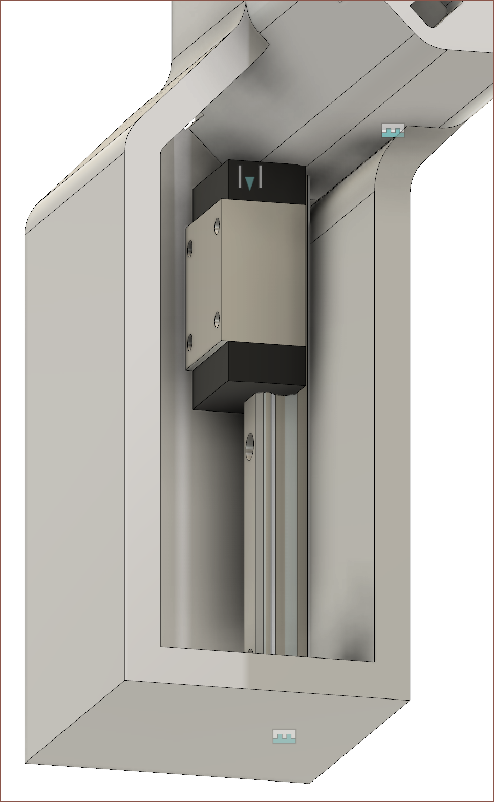
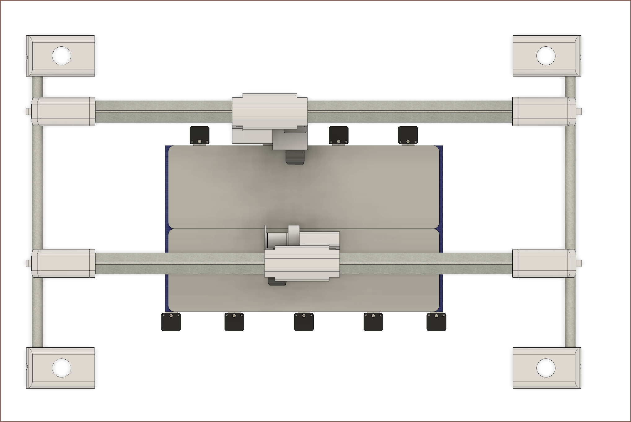 Now I can finally drag the heads around.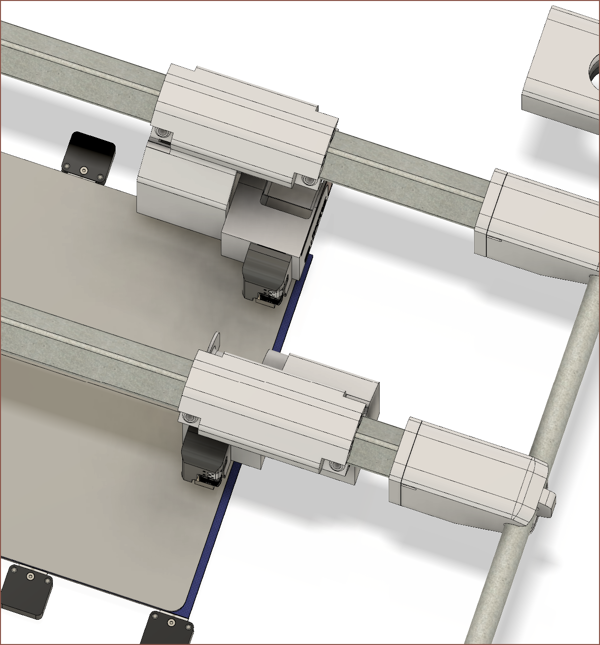
 What distance is that? Fusion: 200mm. Wait, if I play my cards right, I can get a solution I didn't think was possible because of the bowdens.
 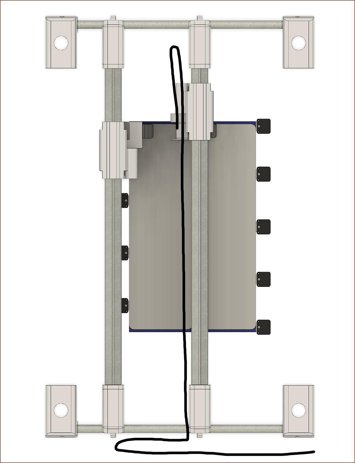 No way. If I have the right Select connected to the left Slime (instead of left to left and right to right as I originally planned), a solution could exist.
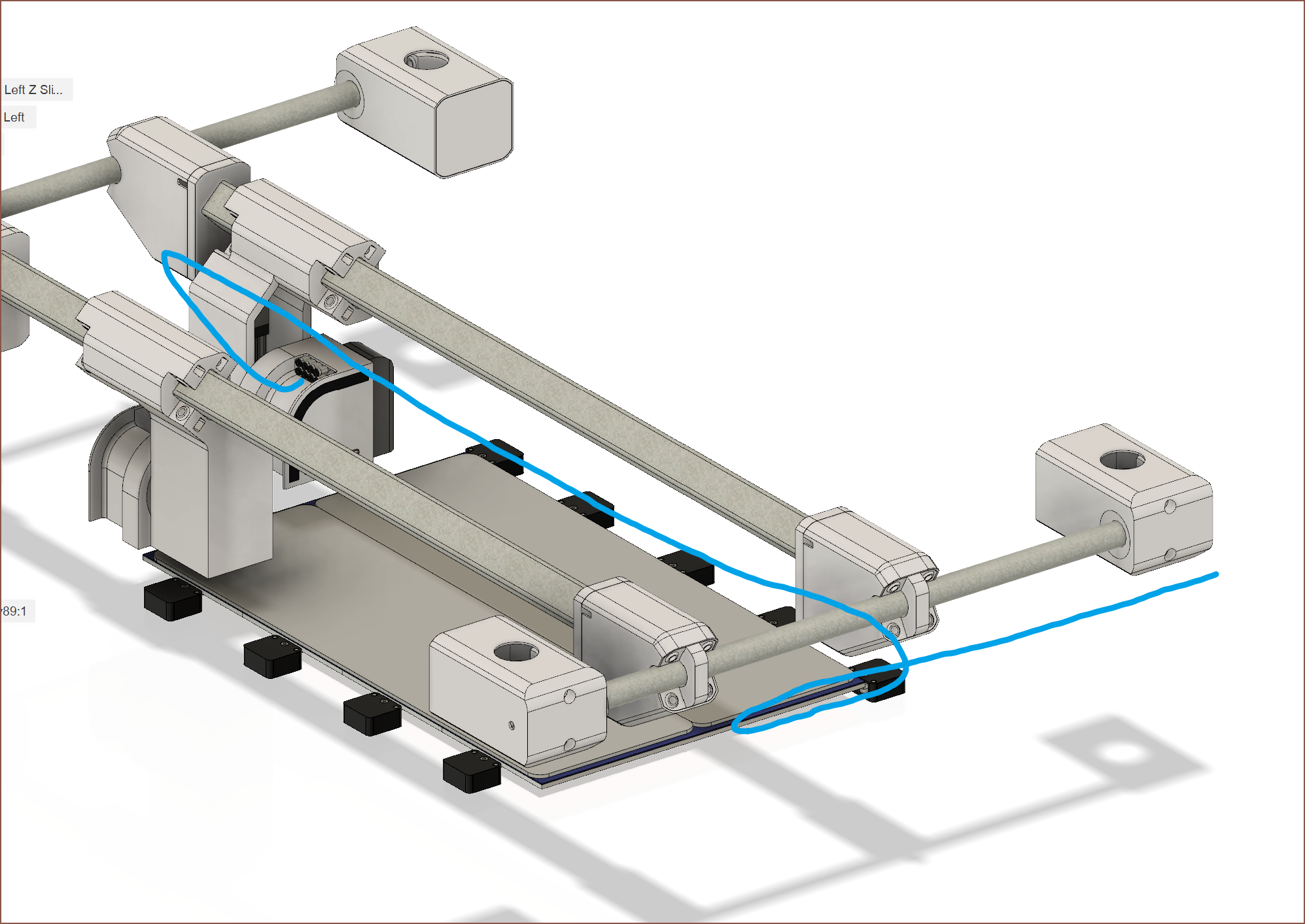 I'm not seeing any problems when taking Z into account either. This alteration would increase the independency of the IDEXY solution. For example, I could do mirror mode on the dual 65x20cm glass beds or access one more tool from the tool bar.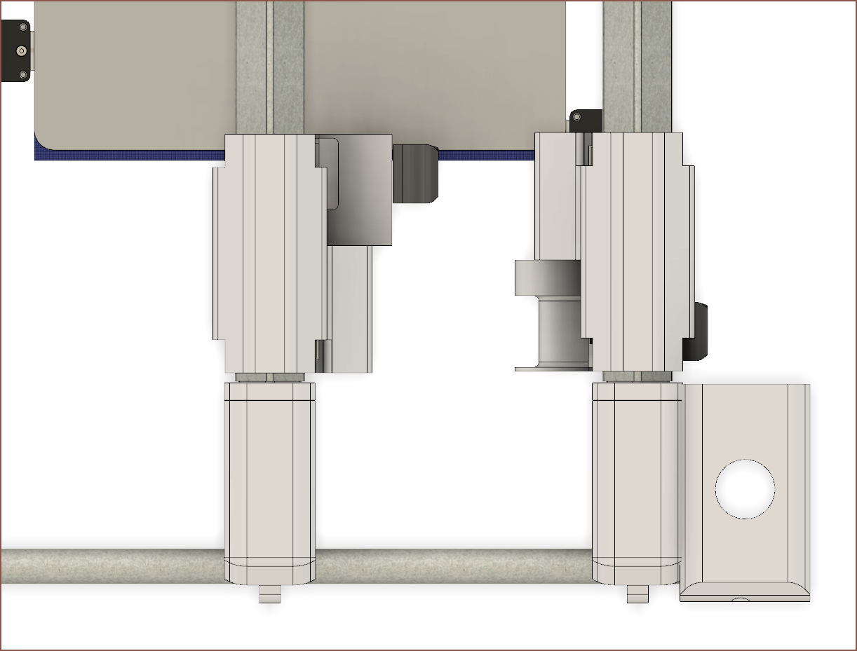
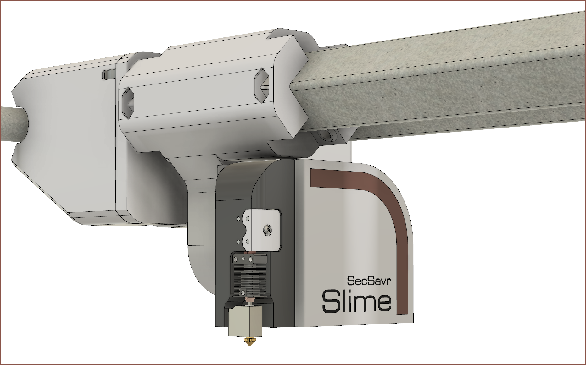 My first guess for the length of the slider was 160mm and it looks to be a good one.
 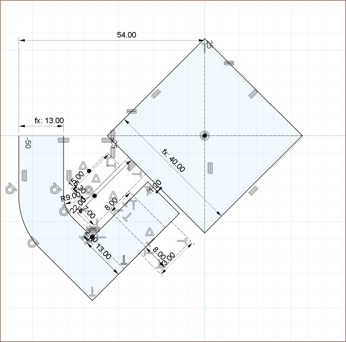 I first tried going around, but that looked to take up too much X space, so I rearranged it:
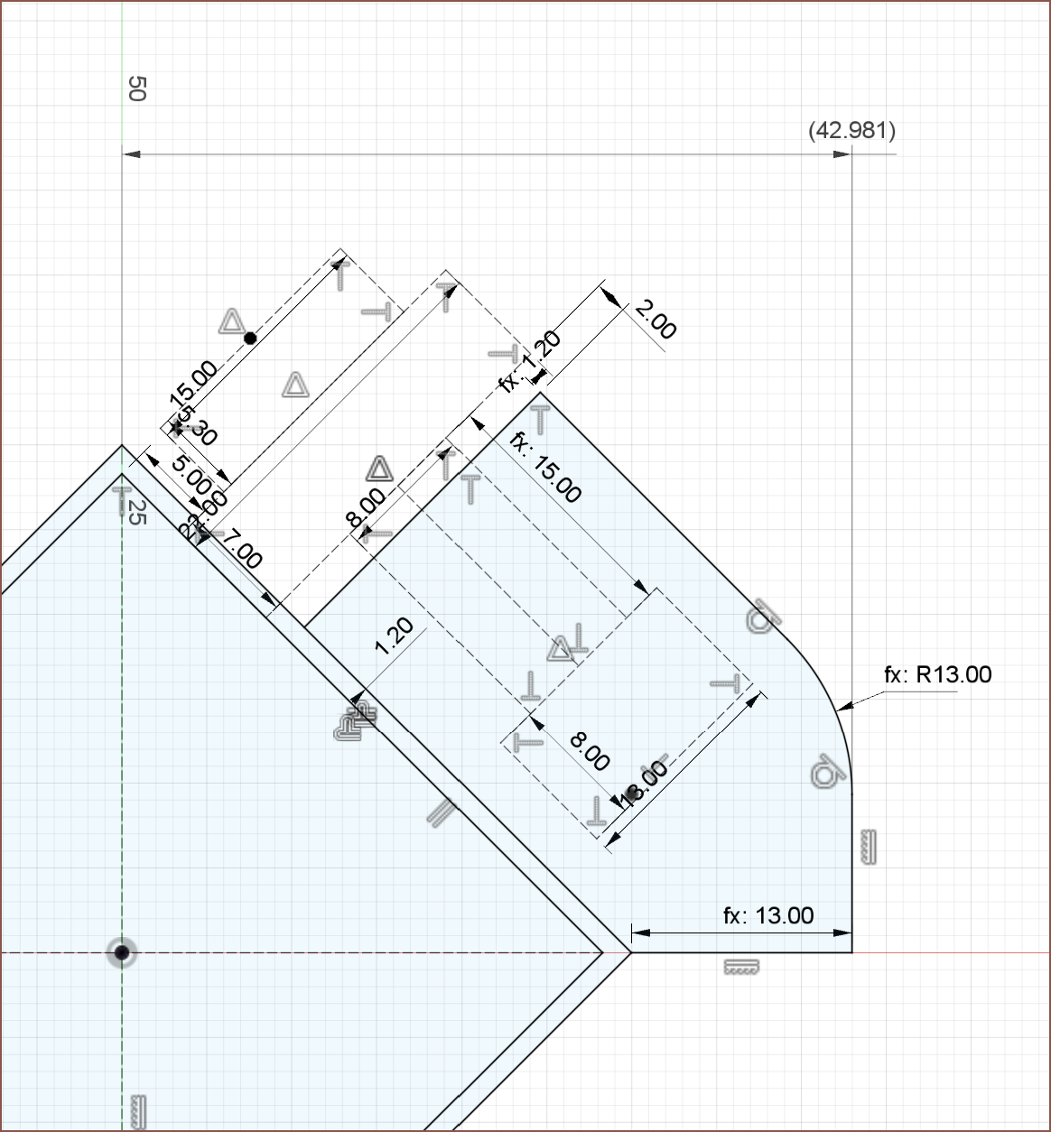 Now looking at it again, I could rotate the slider 90 degrees. Next I tried a couple designs but reverted on the ideas.
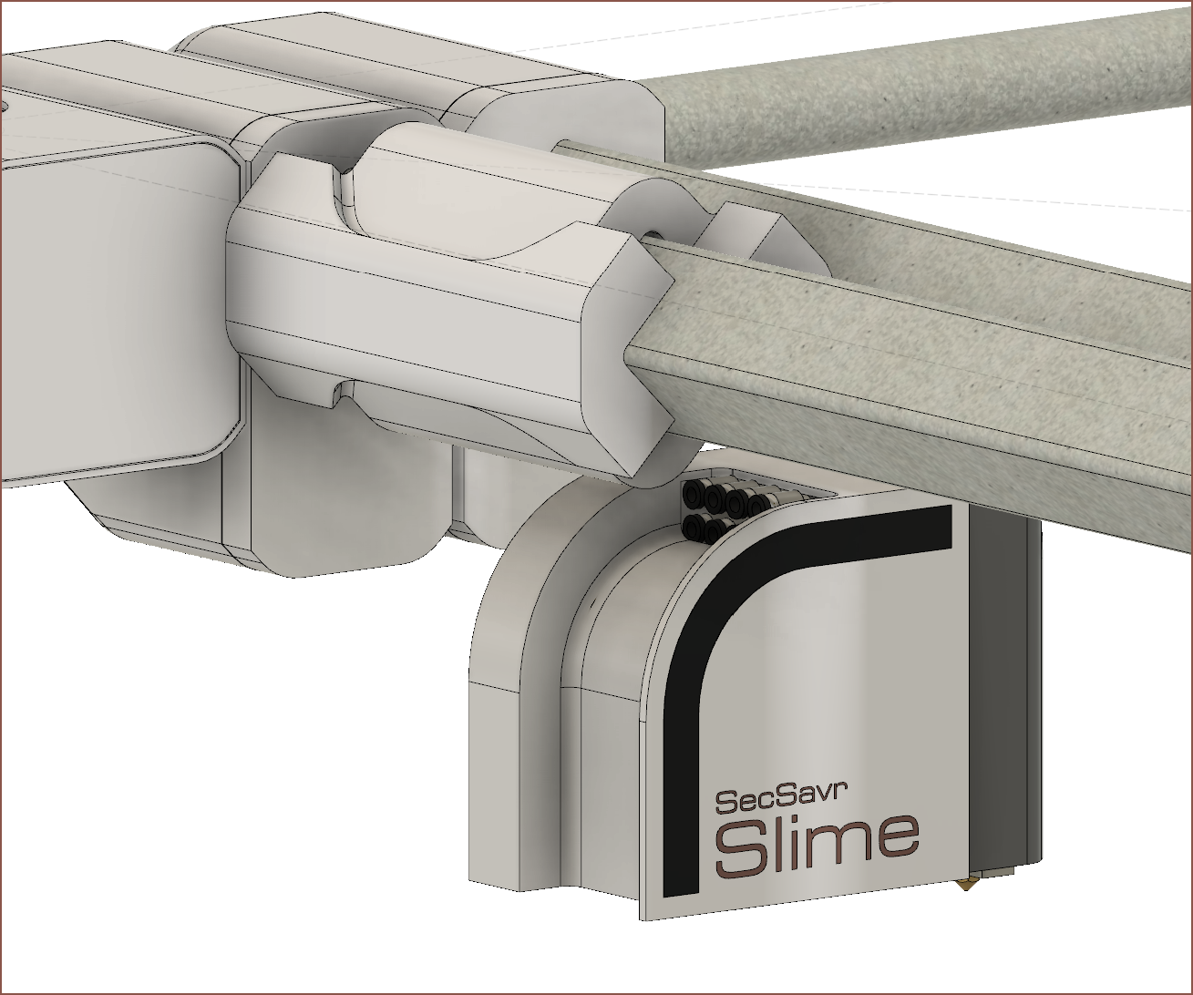 Then I added the temporary arm idea, making sure that it wouldn't hit any adjacent tools when moving moving to the Tool Bar. I decided to do the Tool Bar after this because I had a feeling that I was going to have to move the Slime's down to accomodate the 150mm HGR20 and ballscrew for the mini Z axis, and that's looking to be the case. I might opt for 2 MGN15's instead; it depends on how everything fits in the arm, but 2 MGN's are more expensive than 1 HGR20 by a tad, not to mention having to make sure 2 rails per Slime are aligned would likely complexify assembly and maintenance.
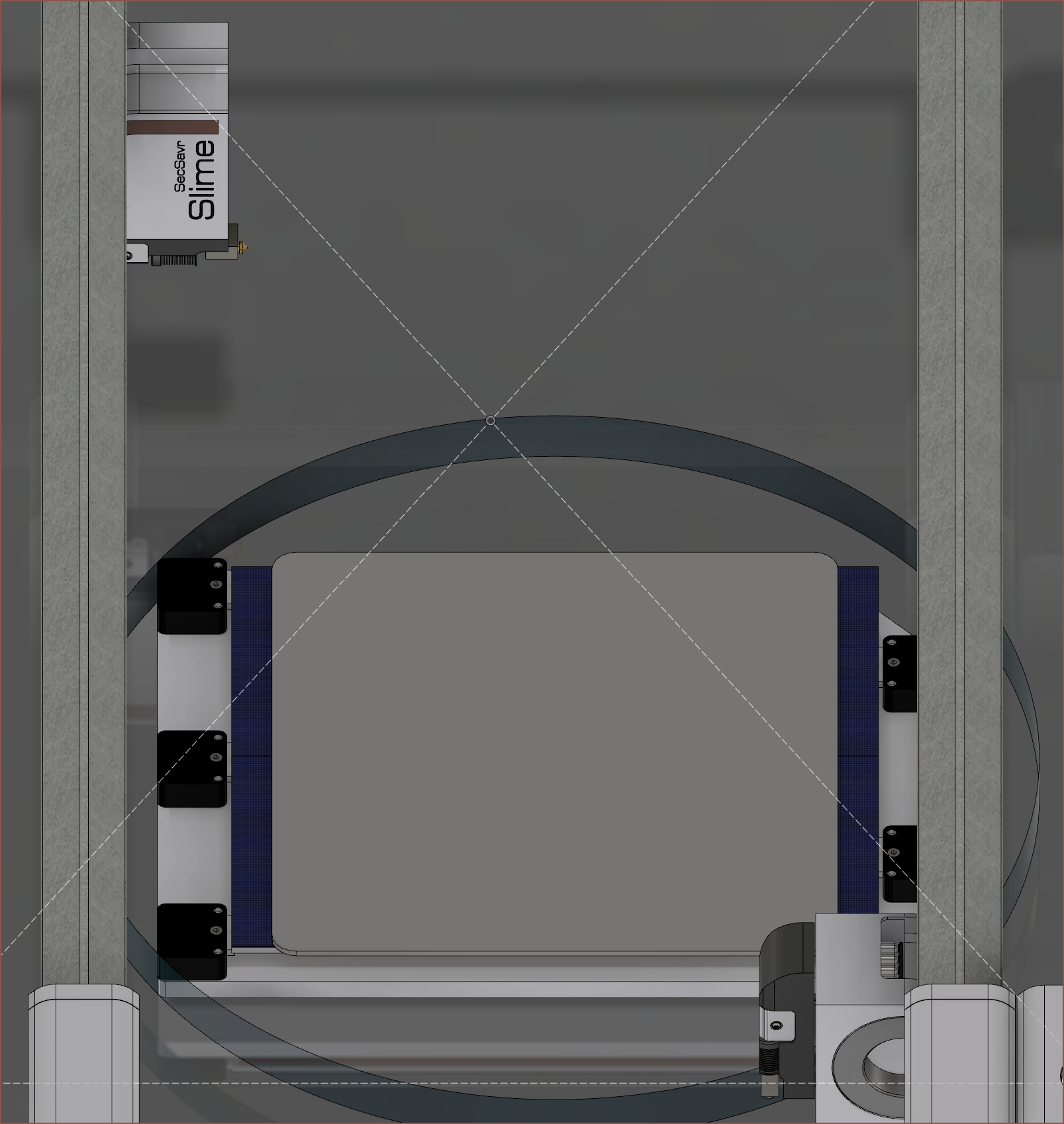 Good thing that I found that 35cm glass because it looks like I'd actually be able to use most of the circular diameter. I'm planning on having the bed rotate so that it can reach the entire area.
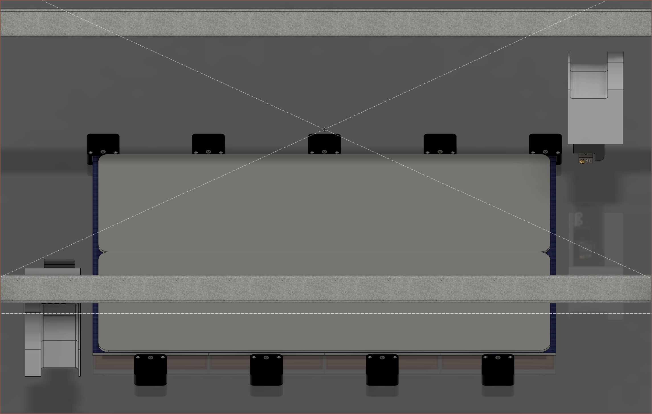 Unexpectedly, it looks like I might actually be able to get both Slimes to reach over the length of the Long Bed.
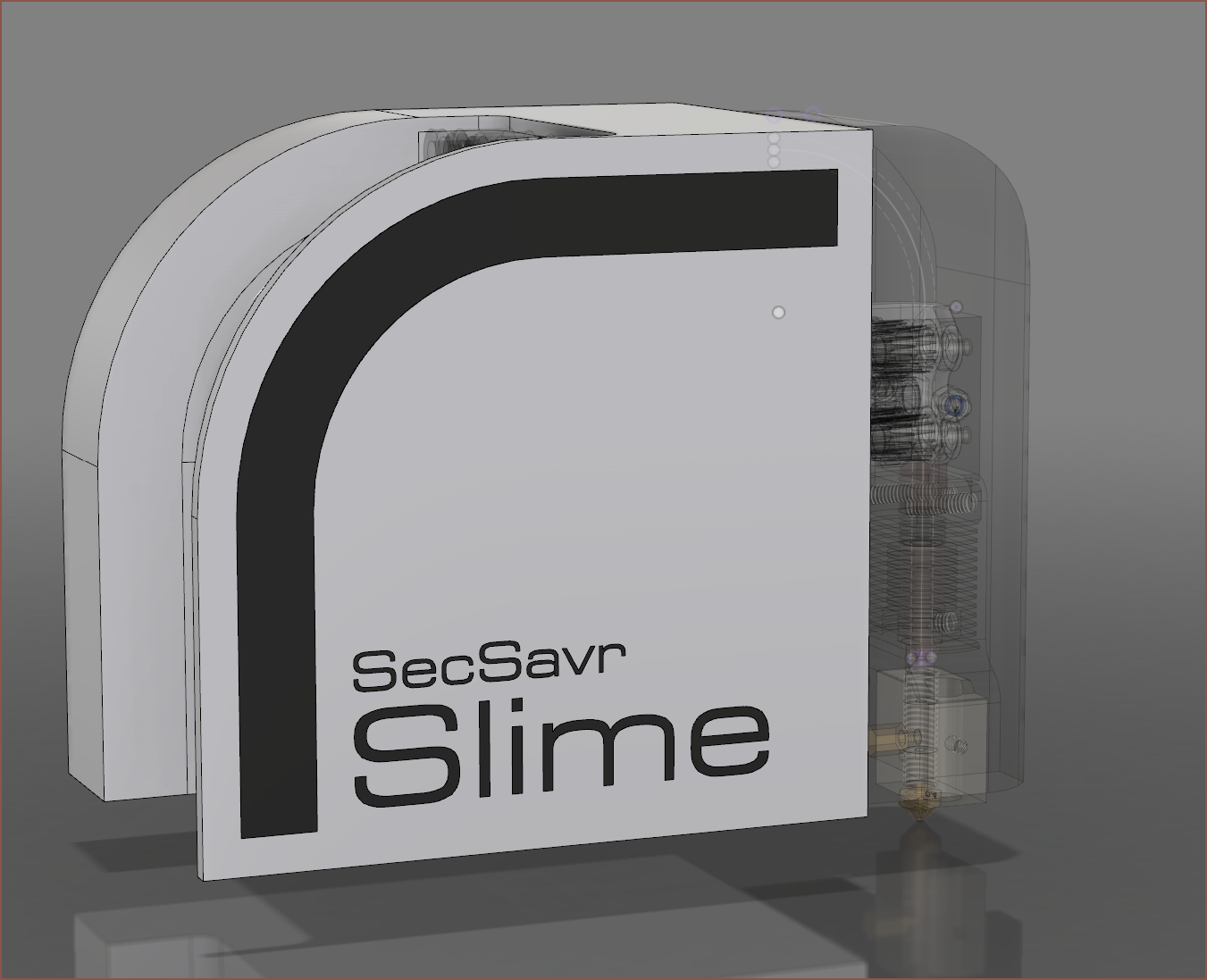
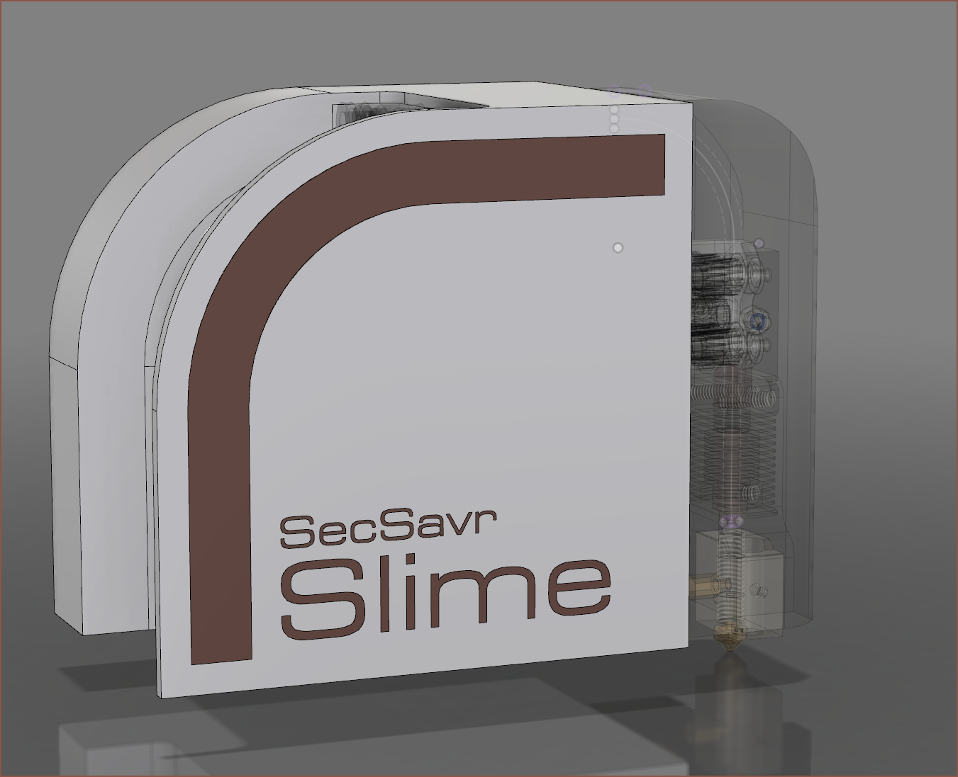 The idea is to have the left Slime as one colour and the right as a different one. I'm thinking a different colour for the text looks better: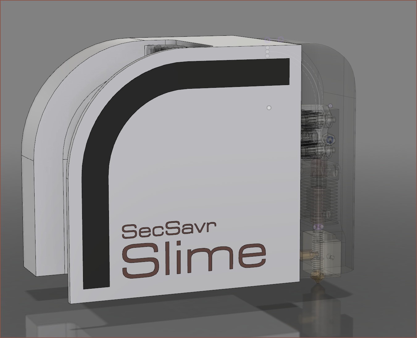
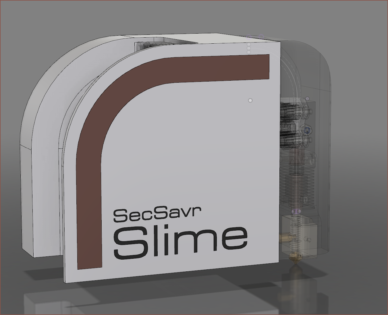 I originally wasn't so keen on this new Slime shape that was needed for the camera, but I'm liking this design change now.
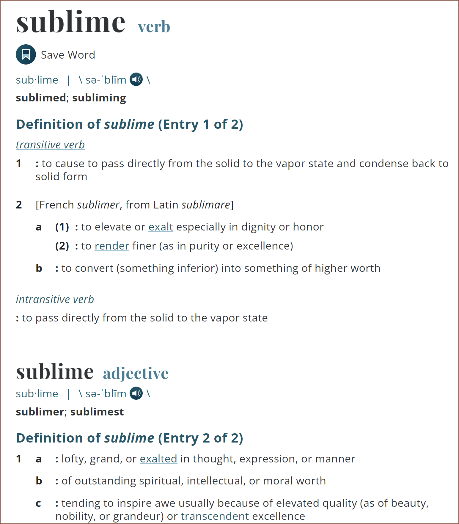 Looking at those adjective definitions, that sounds quite a lot like this SecSavr to me, so it's a possible option.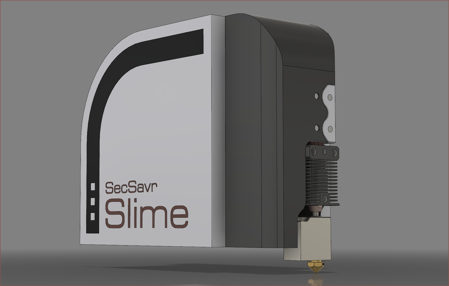
 I think the dots tie together the overall brand (see my logo) and give a bit more of a technical vibe (like some Asus laptops [below]) but I do also like the uninterrupted line too.
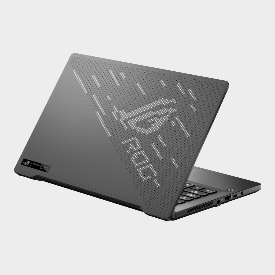 I've done the other side and those 3 dots certainly do add a bit of an "advanced tech" look.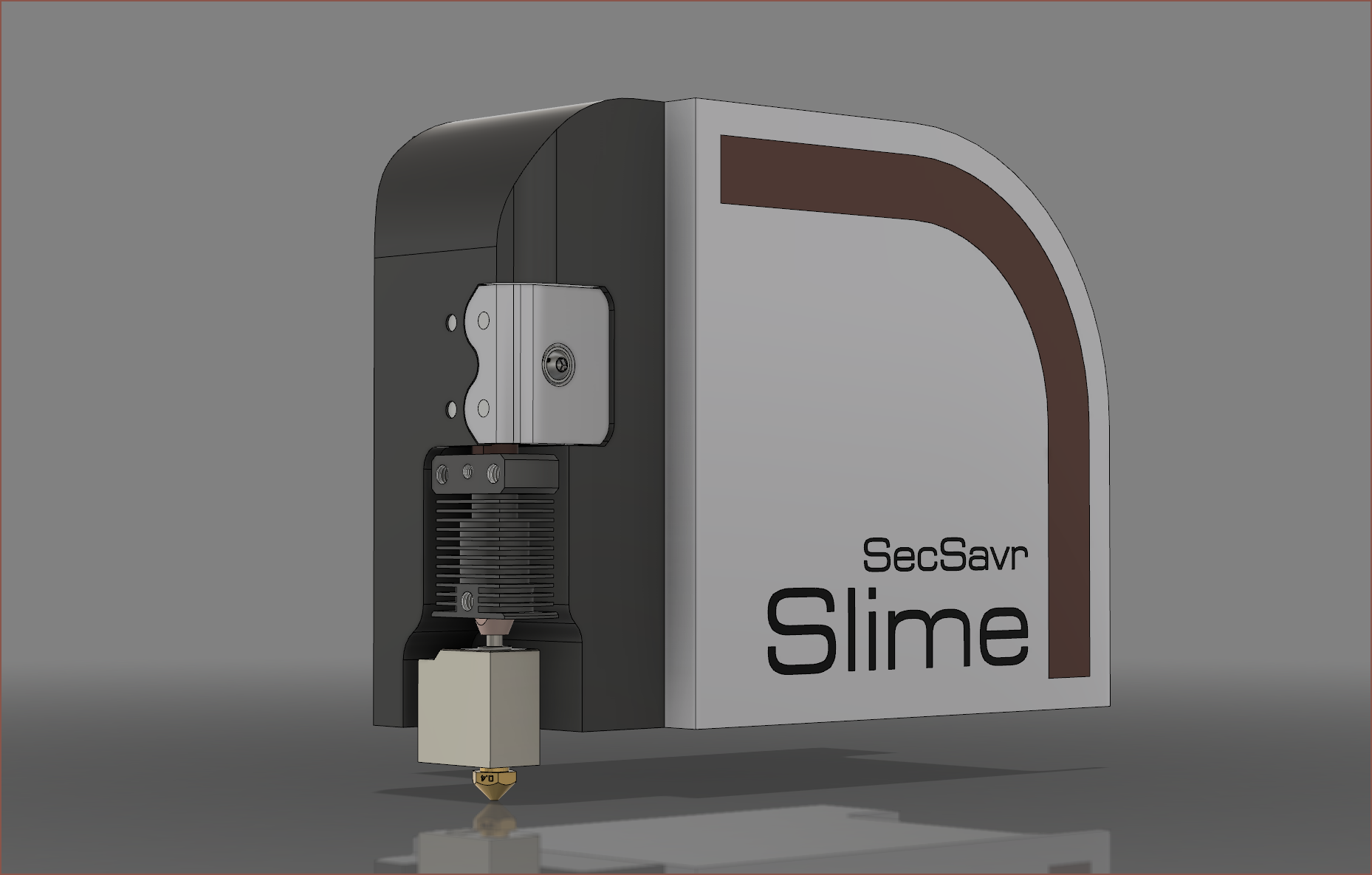
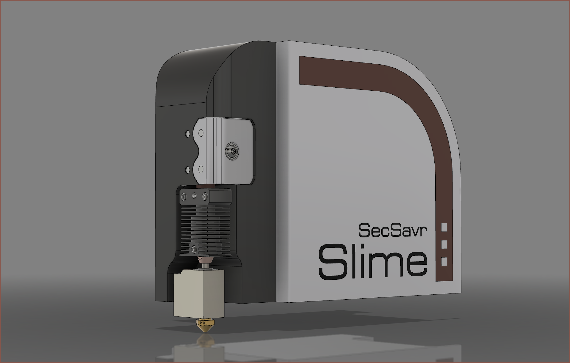 However, in the SleepCinema, the 3 dots look a bit extra: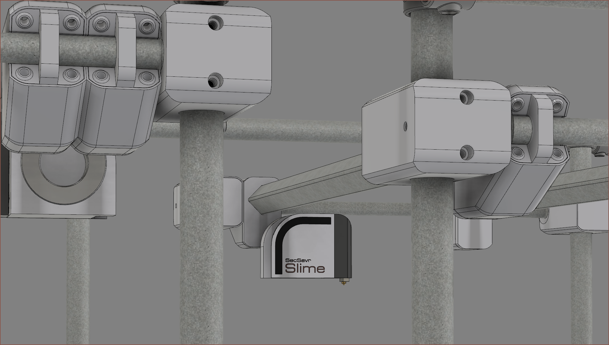
 So I'm going to opt out of the dots.
 I've just extended the second part of the clamp for the Z axis slider to create a cover that matches the Y axis.
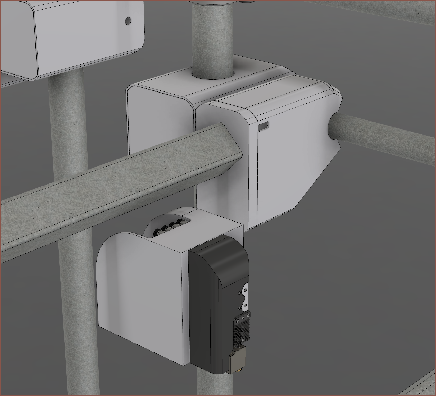 The SecSavr's looking somewhat "sleeper PC" now, but that just means that the design is calming and looking closer to a consumer appliance than DIY or industrial machinery.
 Now I actually imagined that this slider would look a bit differently. I was thinking that I was going to have some additional fin that had a steeper angle than just extending the side curve for the bottom cover section. I also didn't originally have the top cover part in mind, and the white extrusion at the right of the image was invisioned to be a large bracket. Now that I mention it, I feel like there's a sketch I drew in a log somewhere.
 Looking at the CAD, I actually need the entire 1m span to be rollable so that both Slimes can still reach the full 500mm length of the default 3 axis bed. Thus, I'm going to see if I can hold the tube from the inside. This also means that I can move the X/Y motors so that the outer enclosure looks seamless. I plan to use the same overal slider for both sides, so that's why the motors are overlapping in the top image.
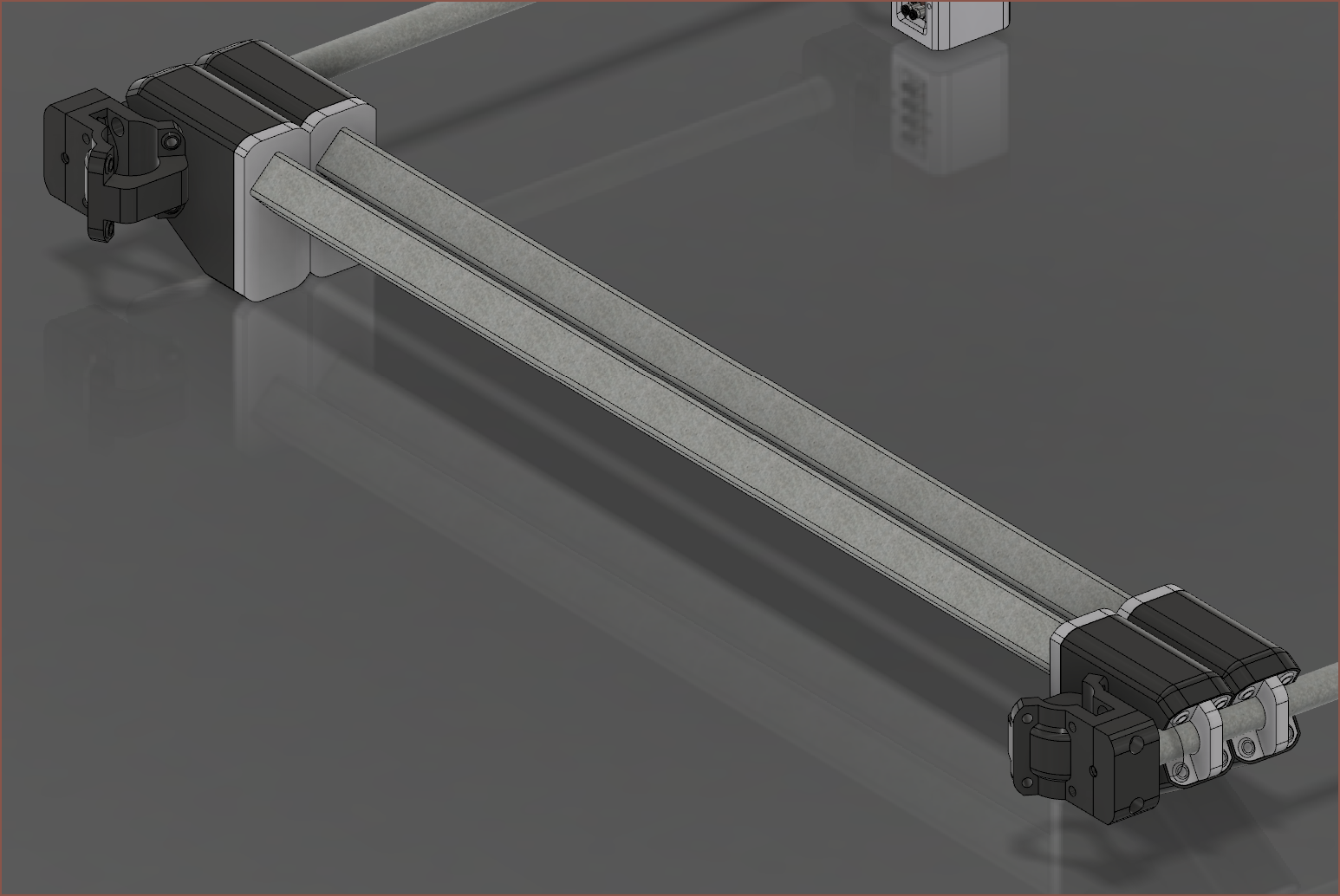 Now this looks more solid and professional. I've got to go back though and rotate the X axis motor 180 degrees so that the X axis belt is as close to the beam as possible. Additionally, I stumbled on another box section supplier and they're much more flexible.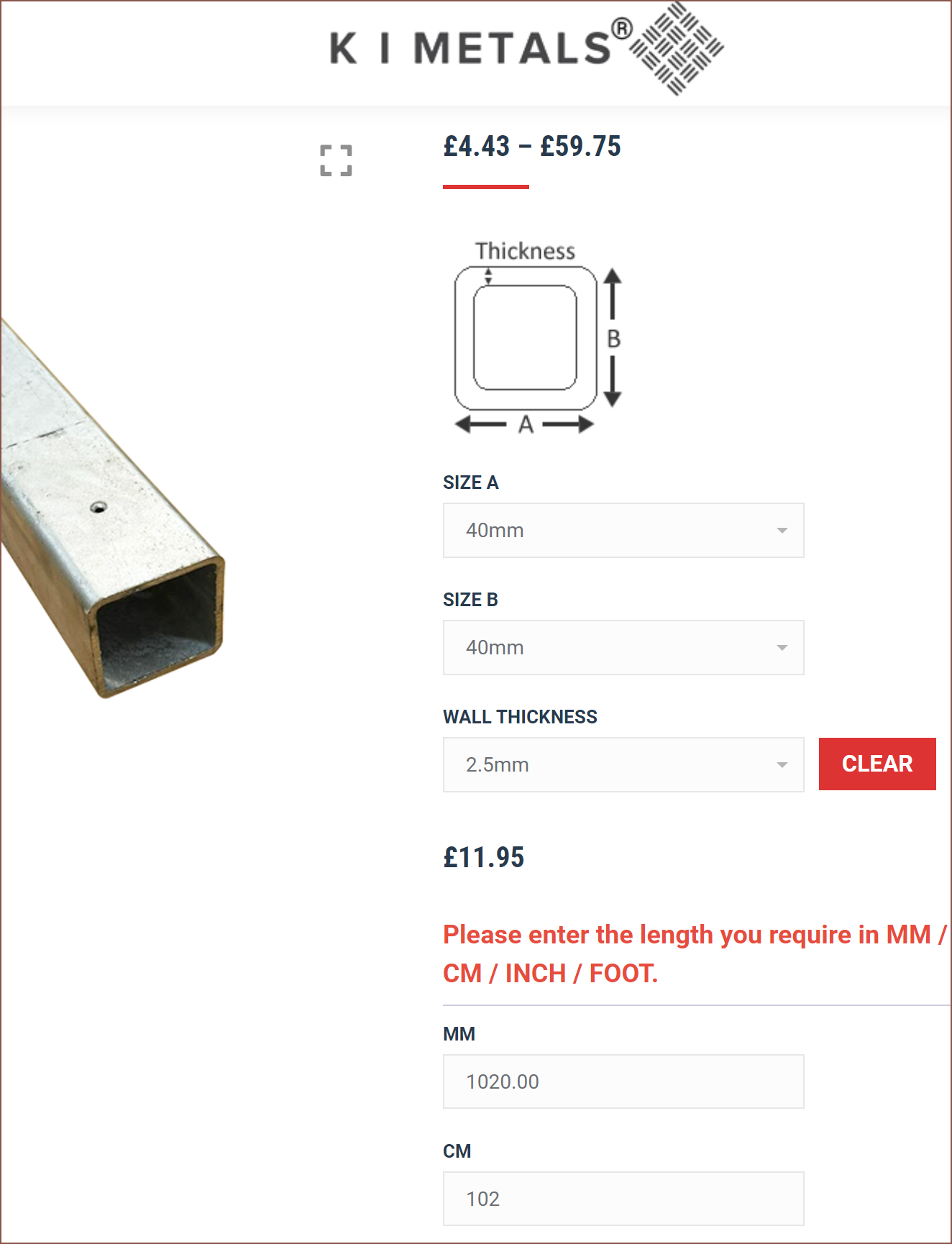
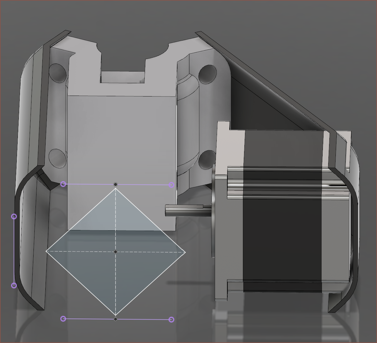
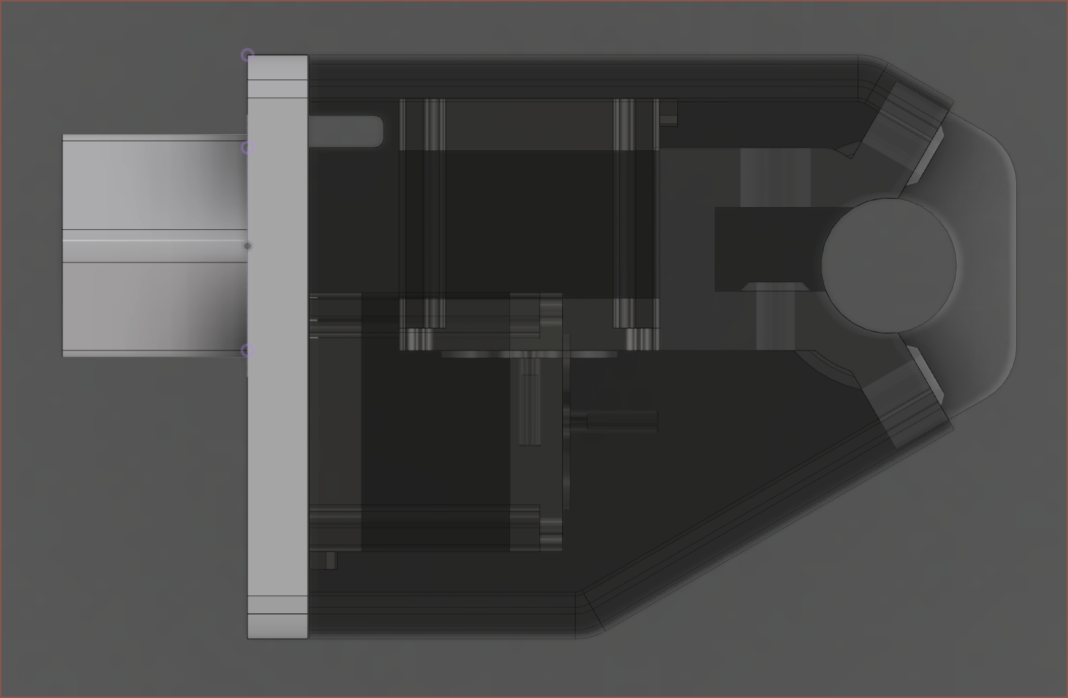 I think that worked out nicely actually. There's a 17mm cutout for the 15mm belt that you can see just after the white block part on the left. As this printer is being designed with CNC milling in mind, they're planned to be dual 15mm 3M belts that interlock like a zipper to hopefully have the same stiffness as a 30mm wide belt. It's an idea inspired from