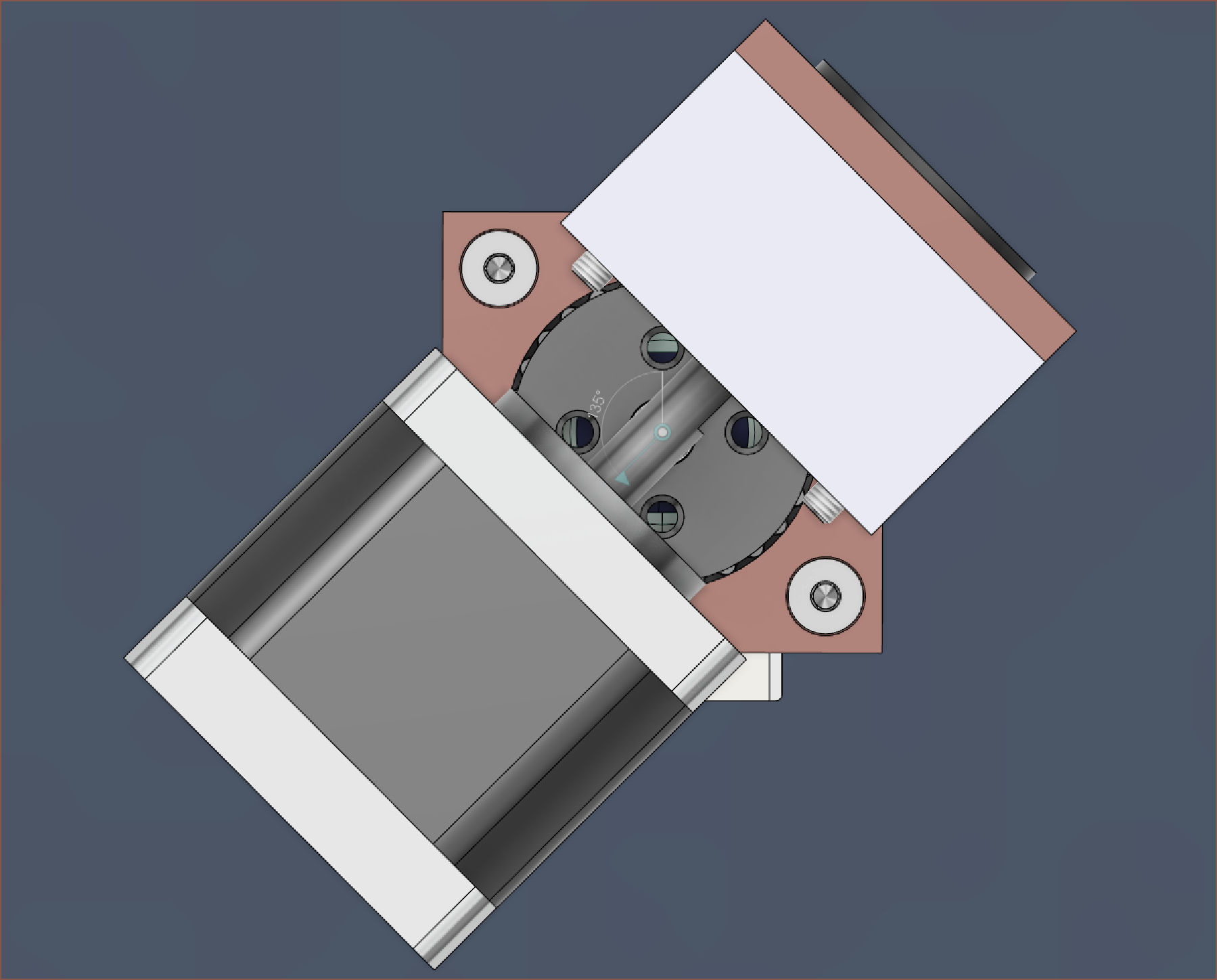
I've made the Nema14 a cylindrical joint (with limits), and I can barely get an extra 15mm of spacing needed for M3x40 countersunk screws whilst still being able to affix the wave generator to the shaft. Now I've done that 4th-to-5th axis idea and it's cutting it close:
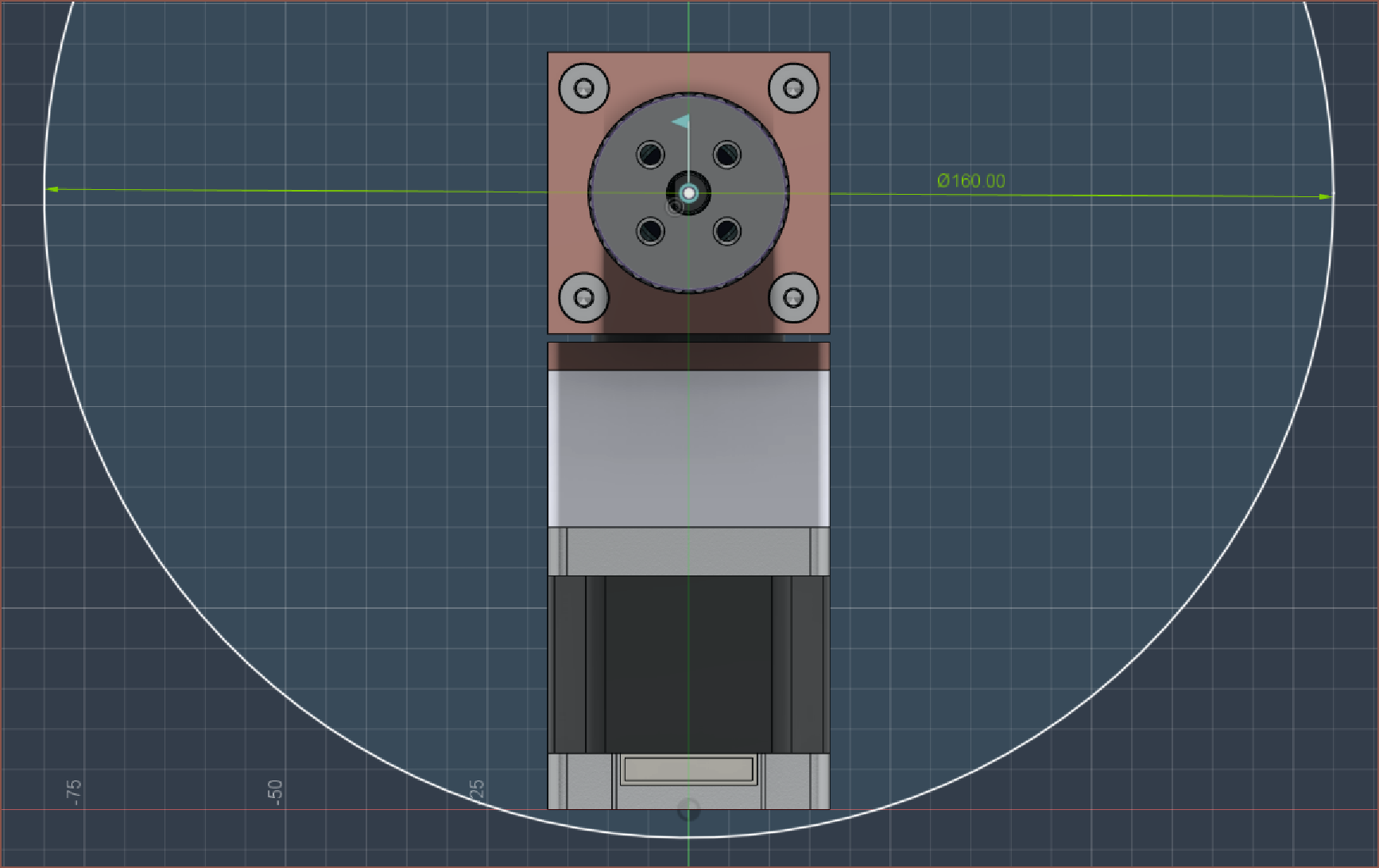
Wough I'm just cutting it close all the way down. I'm only a handfull of millimetres from the new target of 160mm:
Sketching in the other axes, it seems that I can get a 110mm long A2-A3 arm (and the A3-A4 would be half that, at 55mm) and I could stretch that to 112mm. This means that the maximum extension is 165-168mm, barely longer than the LCD panel. I was hoping that I could do this all under 100mm, but the laws of geometry isn't going to let that 5th axis slide:
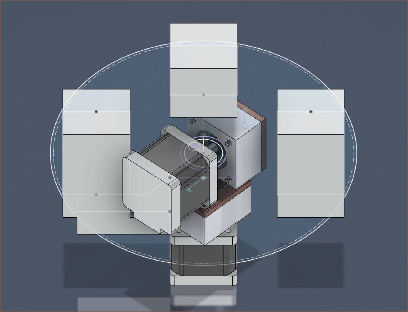
I would have enough space for a 192mm P3 panel though, with an A2-A3 arm length of <=146mm and full extension of 219mm:
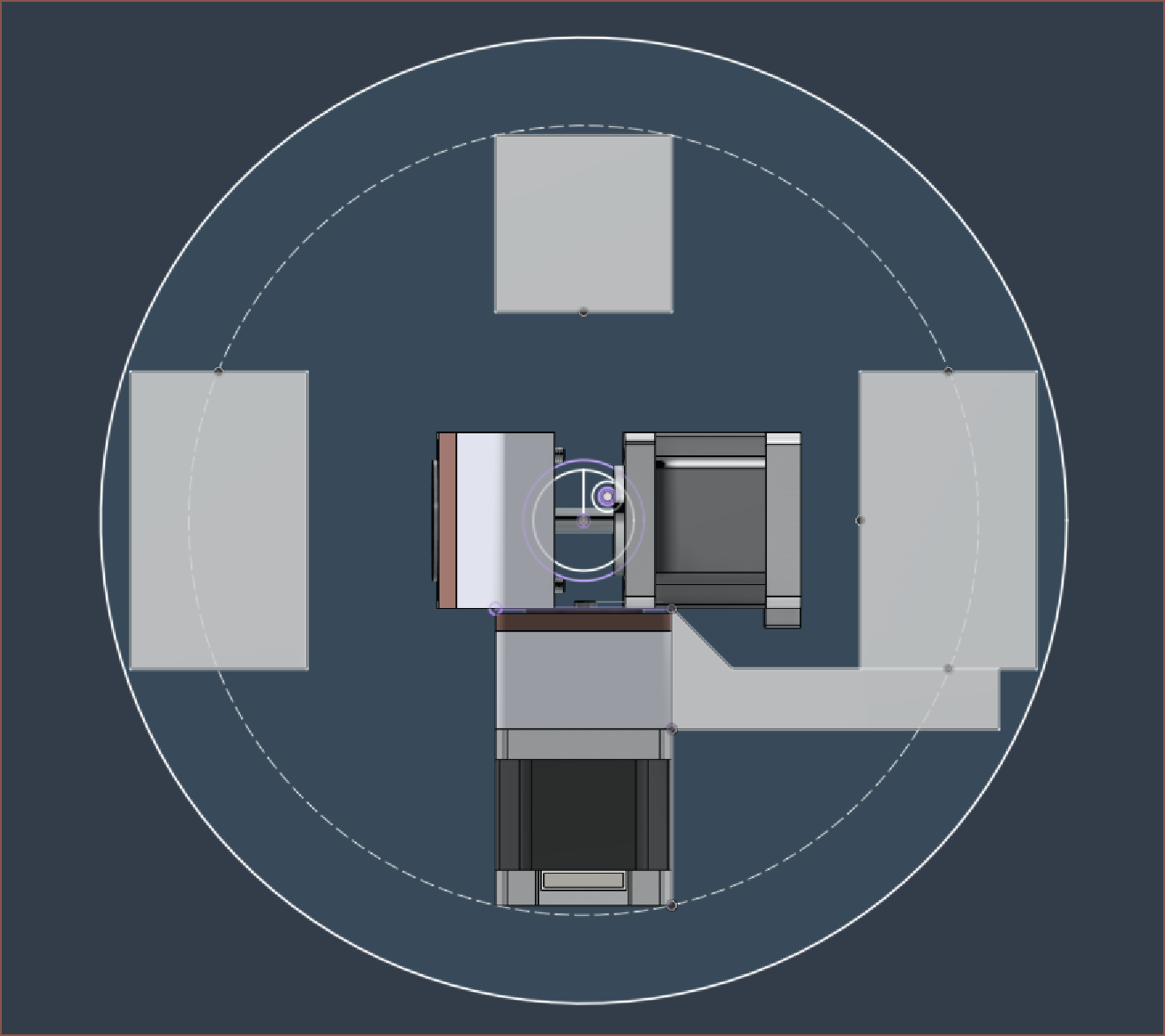
For the 160, the max load is under 1.175kgf and for the 192, it's 0.885kgf if I'm able to get the 10x torque increase on the 0.19Nm motors and assuming the center of mass is at the full extension point. 1200g and 900g seem like ballpark figures, and 160x160x140mm or 192x192x96mm sounds like. I think I'll go 192.
As it turns out, there are both flat and bevelled versions of the LED panel in 192mm size, with identical prices:
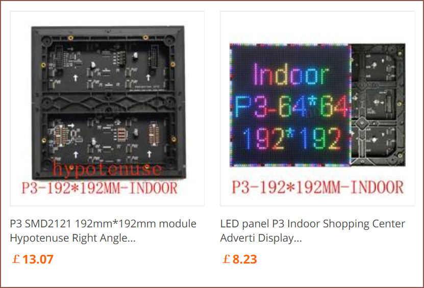
The price difference is £5 and I can reliably get 1kg of material for £10, so unless a printed frame would weigh about 500g, it might be cheaper and more beneficial to go with the cheaper traditional panel.
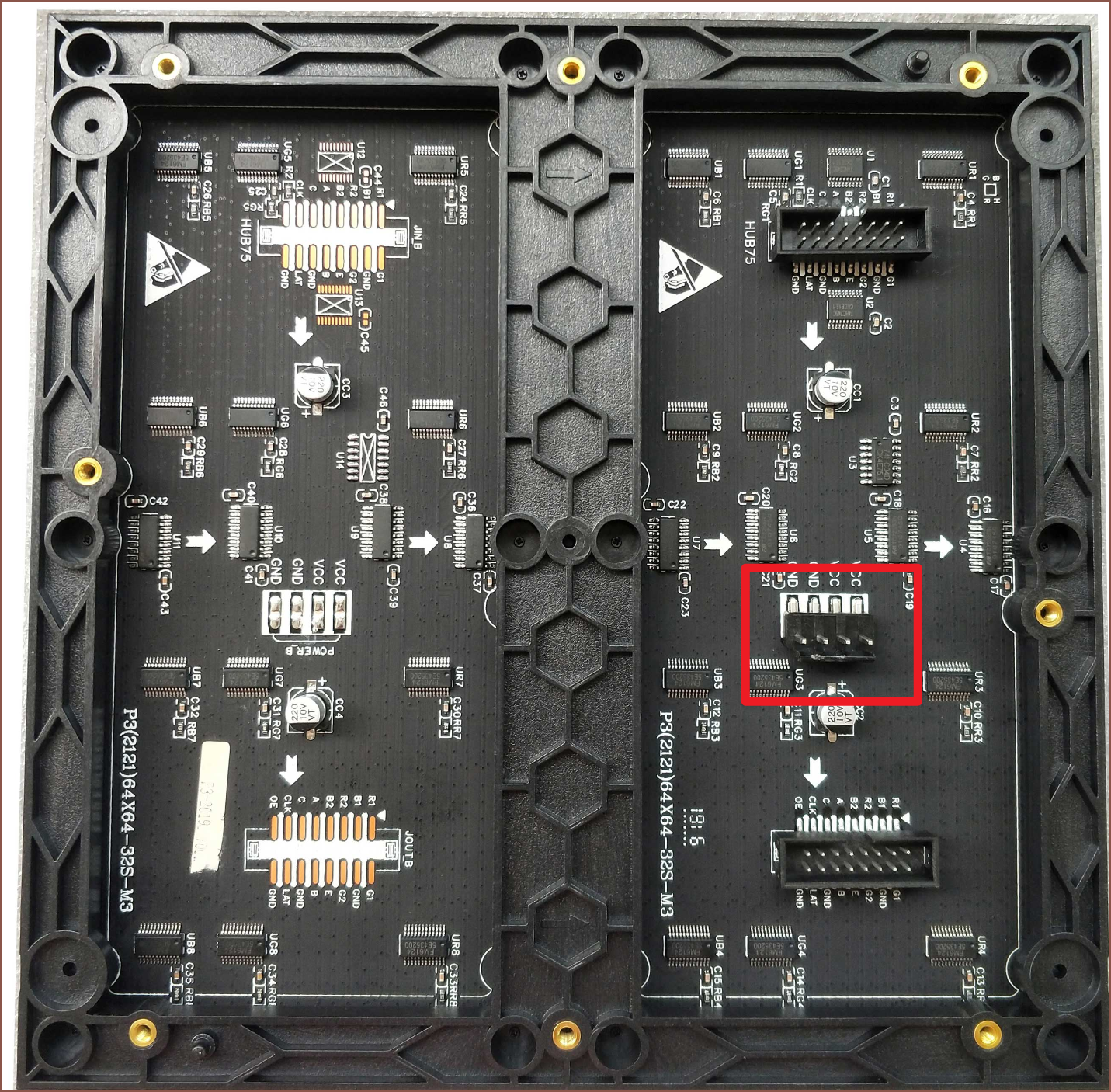
Another benefit from the P3 panels is that the power header isn't right in the middle of the panel where Axis5 needs to be mounted:
It's sounding like 192mm has all the benefits and none of the drawbacks. I get more wall coverage for essentially the same price, and the thickness difference is not something to pass on.
 kelvinA
Discussions
Become a Hackaday.io Member
Create an account to leave a comment. Already have an account? Log In.