Yesterday, I was thinking "I know how to model this" and started researching and modelling the new harmonic drive and looking for the components I want to use. I thought 14:1 was a good reduction, and it's coincidental because if I can get over 70% efficiency, I'd get a 10X multiplier of torque.

It then kind of turned into a goal to:
- Only use the same amount of tubes as the amount of teeth a traditional harmonic drive would use.
- That means 28 + 26 = 54 tubes, as opposed to the 3D printed designs (mine included) that had both input, flexspline and output teeth. This would be 28 + 26 + 26 = 80 tubes.
- Get as many of the high wear or precision contacts to be metal-on-metal as possible. If this is not possible, see if UHMW tape can be applied to the surface.
- Only use 2 deep-groove ball bearings.
- Ensure flex-spline durability.
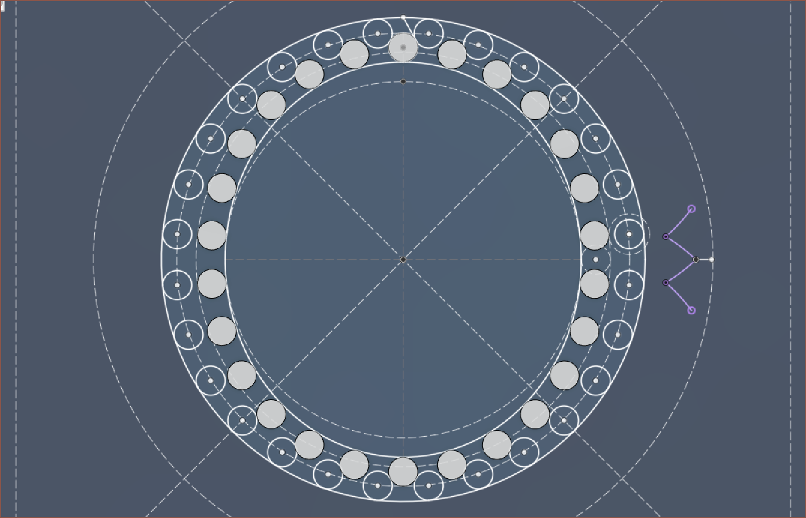
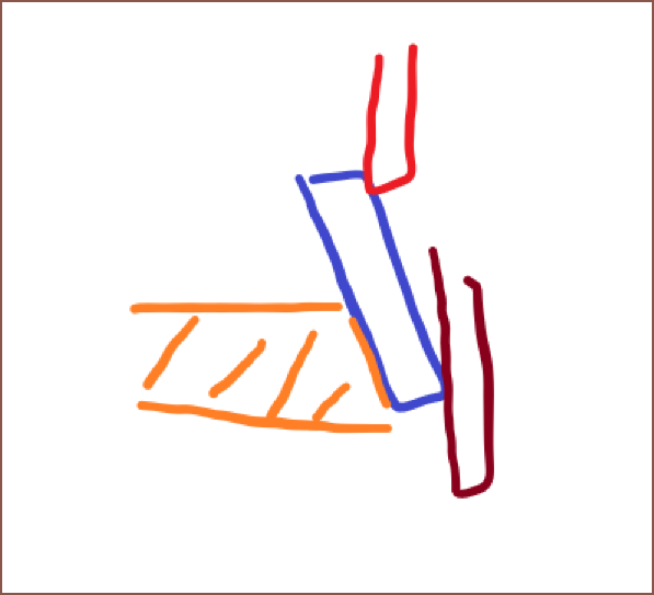
Part of these goals were because I did some planning and thought that I could obtain a solution where the tubes slid over a single, solid wave generator:
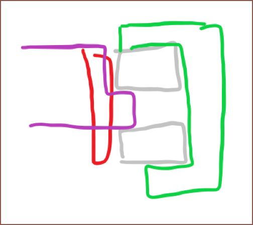
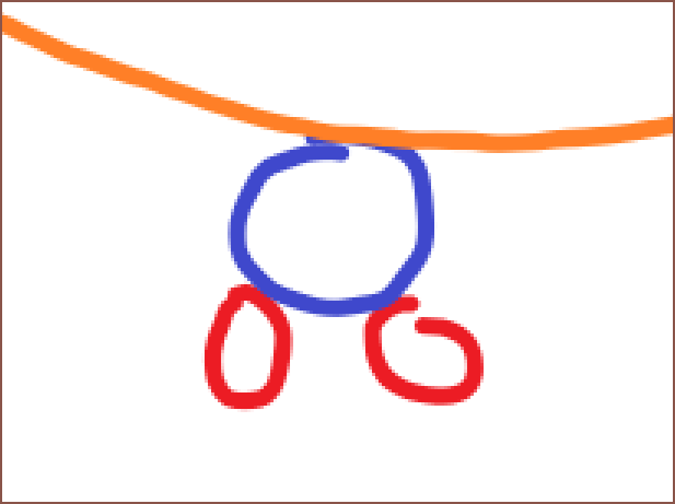
I was still kind of clueless as to how I was going to actually model the design, so I drew up a sketch:
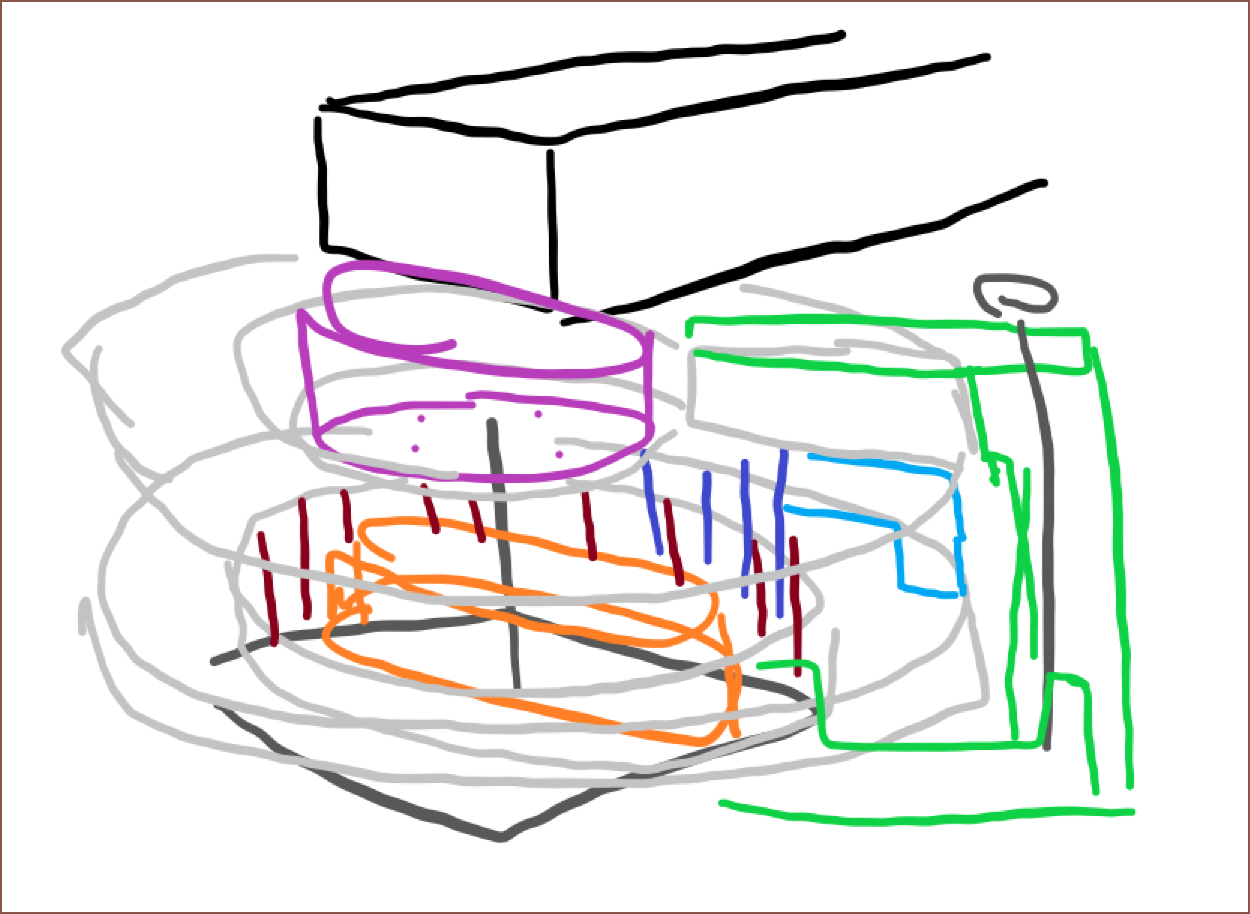
Now, knowing how I needed to model, I started, taking advantages of the coincidence that the Nema14 bump is 22mm, the tube is 1.5mm and the inner diameter of the 6705-2RS is 25mm.
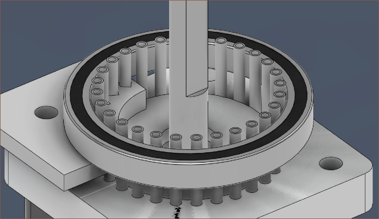
This is where I've been for hours now, because I'm mentally doing simulations and one thing or another isn't working out.
- My original flex idea was actually having these tubes tilted in like a cone, because it'll be easiest to flex while still having low displacement at the rigid end.
- Then I was thinking of something similar to my first design, but I have to assume that the tubes are rigid bodies and so may not be able to properly interface with either the input of output tube-teeth. Even if that was the case, I'd need to use BB-balls / loose ball bearings like the orange one in a video in the previous log.
- I thought of having the output being completely rigid and with 28 teeth. Then, the flexing needed to take place on the bottom half and I don't have an idea how to fix it in place.
- I considered something spring-loaded, but springs don't have an infinite fatigue strength and I'd likely introduce backlash into the system. 3D printed compliant springs probably wouldn't last either... not at the size I need anyway.
- I also considered something similar where balls or tubes are pushed into place when needed and then are free to roll over the tubes when not, almost like some kind of piston x kinematic mount.
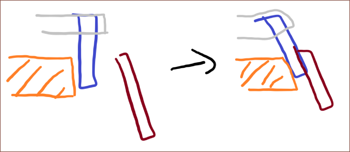
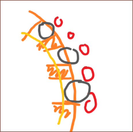
I guess a slightly more detailed sketch would look like this:
The tubes/pins/balls are pushed into the output-tubes when required, but are free to move out of the way when not. Instead of the flexspline requiring the restorative force, the output teeth are also the restorative force.
I think a tube or pin would work better than a ball, especially a pin with rounded corners to prevent binding.
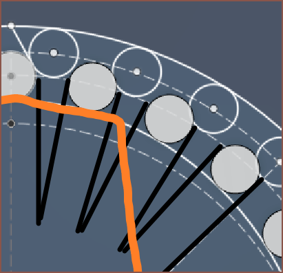
Ideally, the tube/pin would be fully defined:
I think the issue with this one is going to be wall thickness of these small pathways?
It's most similar to a heliocentric gearbox:
I'll have to do more thinking. I'm both trying to figure out what won't work just as much as what does, because that makes all mental simulations more accurate.
 kelvinA
Discussions
Become a Hackaday.io Member
Create an account to leave a comment. Already have an account? Log In.