-
First Attempts At Avian PPG Signal Capture
04/21/2022 at 00:35 • 0 commentsSeasons
Spring is a time of new growth. A shrugging off of the last Winter's hibernation and an awakening of Love's pleasures. A chance for the birth of new life. Yes, this is going somewhere.
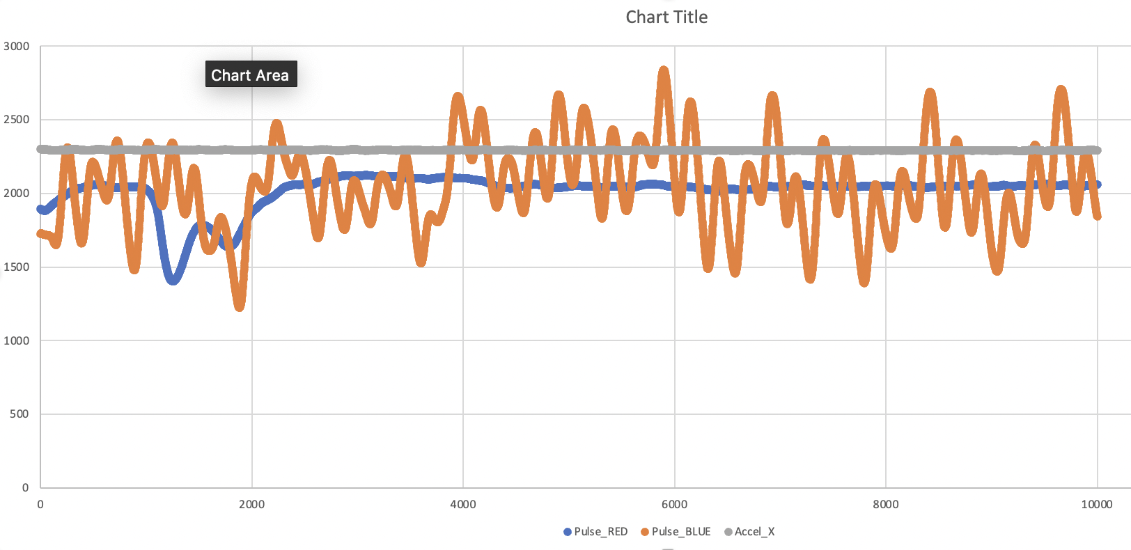
Jay got some good and interesting data from hummingbirds recently. The first try was about a month ago, and it was not super successful. Here's a screenshot of the Arduino Serial Plotter from that time (check out the github readme for this project to learn more about the data we're collecting).
![]()
In the above graph, blue and orange are Pulse Sensor signals, and the grey is from the accelerometer. Both Pulse Sensors are in contact with the hummingbird on the [anatomical sites needed]. There seems to be a high frequency signal on the orange trace, but it's not very pretty. PPG can be very sensitive to movement noise. The kit I sent included some double sticky tape but I don't think that was employed for this test. Jay had to focus on his 'real' research, so it wasn't until this week that he had a chance to try again.
2nd 1st Try
This is all new and fresh. We don't have any corresponding recorded data sets to accompany the following screenshots, but we're going to work with what we have. Starting with the data, because that's always the most fun. This is an example of a clear signal trace that we think is a stable hummingbird heartbeat captured with Pulse Sensor. This is super duper guess and speculation. Based on trust, anatomy, and physics. I think what follows is kinda legit.
![]()
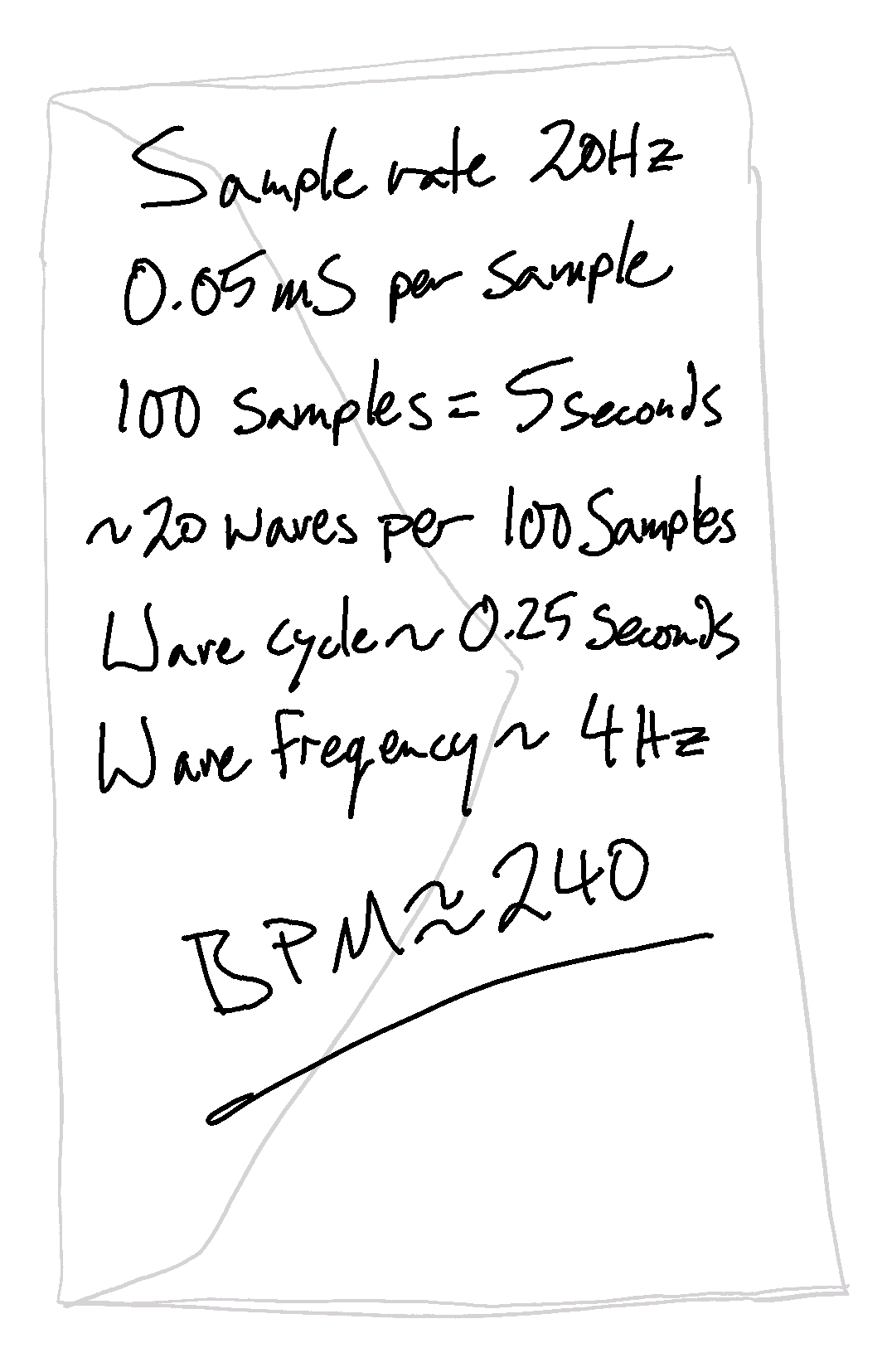
OK, there's a lot of lines there. Don't pay attention to the colored boxes and labels at the top left, they will just confuse you. This signal is sampled at about 20Hz (software timer). The Y axis is in counts of the Teensy ADC. The X axis is incremented with each sample. Notice that Arduino plots a vertical grey line every 100 samples. Only one Pulse Sensor was placed on the bird, and the other sensor traces should be ignored. The red signal trace corresponds to the Pulse Sensor in contact with the bird, and It looks like something is there! I counted the waves per 100 samples and here's a back of the envelope signal frequency estimation.
![]()
That's not unreasonable. However it requires verification. The good news is that while Jay was holding the bird, he was able to feel the respiration rate, and he says it was not in sync with the signal in the red trace above.
[put the gif about needing more data here]
Further test involved 'sticking' the Pulse Sensor to the accelerometer to kind of couple them to the same site. Reason behind that was to try and identify any movement noise in the Pulse Sensor signal that we might have to deal with. Here's what that looked like:
![]()
OK, there's a lot of lines there. Don't pay attention to the colored boxes and labels at the top left, they will just confuse you. Here's a breakdown of the data traces.
Trace Color Data Source Comments Blue Sample Counter byte size counter with rollover Red Pulse Sensor In contact with bird Green Pulse Sensor Not used, ignore it Orange Accelerometer X hmmm Purple Accelerometer Y errrrrr Grey Accelerometer Z ahhhhhh First of all, the resolution of any accelerometer signals in this graph is just garbage. There might be something there, but any regular anatomical movement that the bird may cause, like breathing, seems to be very slight. I thought that the accelerometer might pick up respiration, but I'm not seeing anything at this scale. I'll wait for the data.
Then there's that same steady ~20Hz wave still visible in the red Pulse Sensor signal. It looks like it's consistent across the screenshots that Jay sent me. It's gotta be something.... I've put more snaps and video on the github.
The Birds And The Bees
Anatomy Lesson
![]()
This is a hummingbird skeleton. Notice the long flat bone? It's part of the sternum, and it's called the 'keel' in bird bone speak. Strong flying muscles attach to the keel (down-stroke?). The keel is visible on a living specimen as a ridge that runs along the chest belly. You can see it here if you look closely.
![]()
The bird wrangler in this photo is gently blowing on the bird belly of the speckled hummingbird which deflects the feathers and exposes what's called the 'brood patch'. What's that you say? How can we see the belly skin of the hummingbird?
Here we have come full circle to the rites of Spring and the glory of pro-creation. But once the party's over, a bird's gotta take care of those eggs! The brood patch provides cozy incubating warmth to growing hummingbird embryos and the next hummingbird generation. This body part has been super duper evolve-gineered to be the absolute snuggliest possible egg cuddler. That's why there's no feathers there.
And, it seems, the spot just adjacent to the keel is a good location to acquire PPG.
That's where we're at. Next time, we'll have some data to play with.
-
ship it
03/17/2022 at 22:39 • 1 commentThere comes a time in every project's life where it just kind of needs to be done.
I'm at that point.
Test drove it and fixed a few bugs. The github readme is up to date for notes on UI.
![]()
-
parts coming together
03/14/2022 at 20:33 • 0 commentsLots of updates happened over the weekend. Got to ship out this week !
Components are soldered in, mostly.
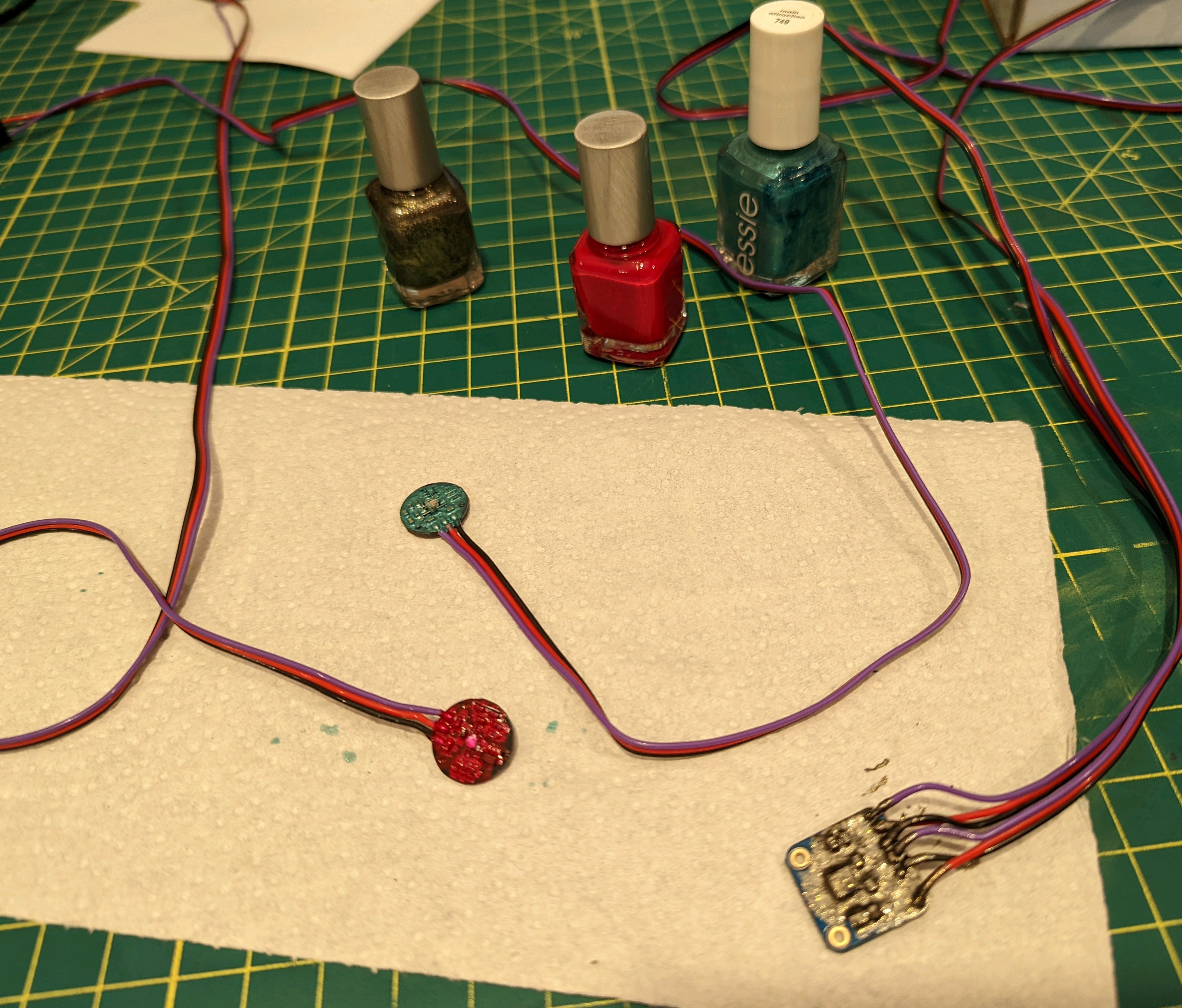
I used nail polish to 'conformally coat' the exposed circuitry on the sensors.
Turns out that the accelerometer that I have in my bins is +-16g. That's way to sloppy for the kind of movement noise we're hoping to find. I've put in a purchase for a +-3g sensor in the same family.
I'm using the Time library to timestamp the files. There's only limited metadata written to the CSV files. This could be improved, but not necessary since the recording will take place alongside other data collection and logging logs.
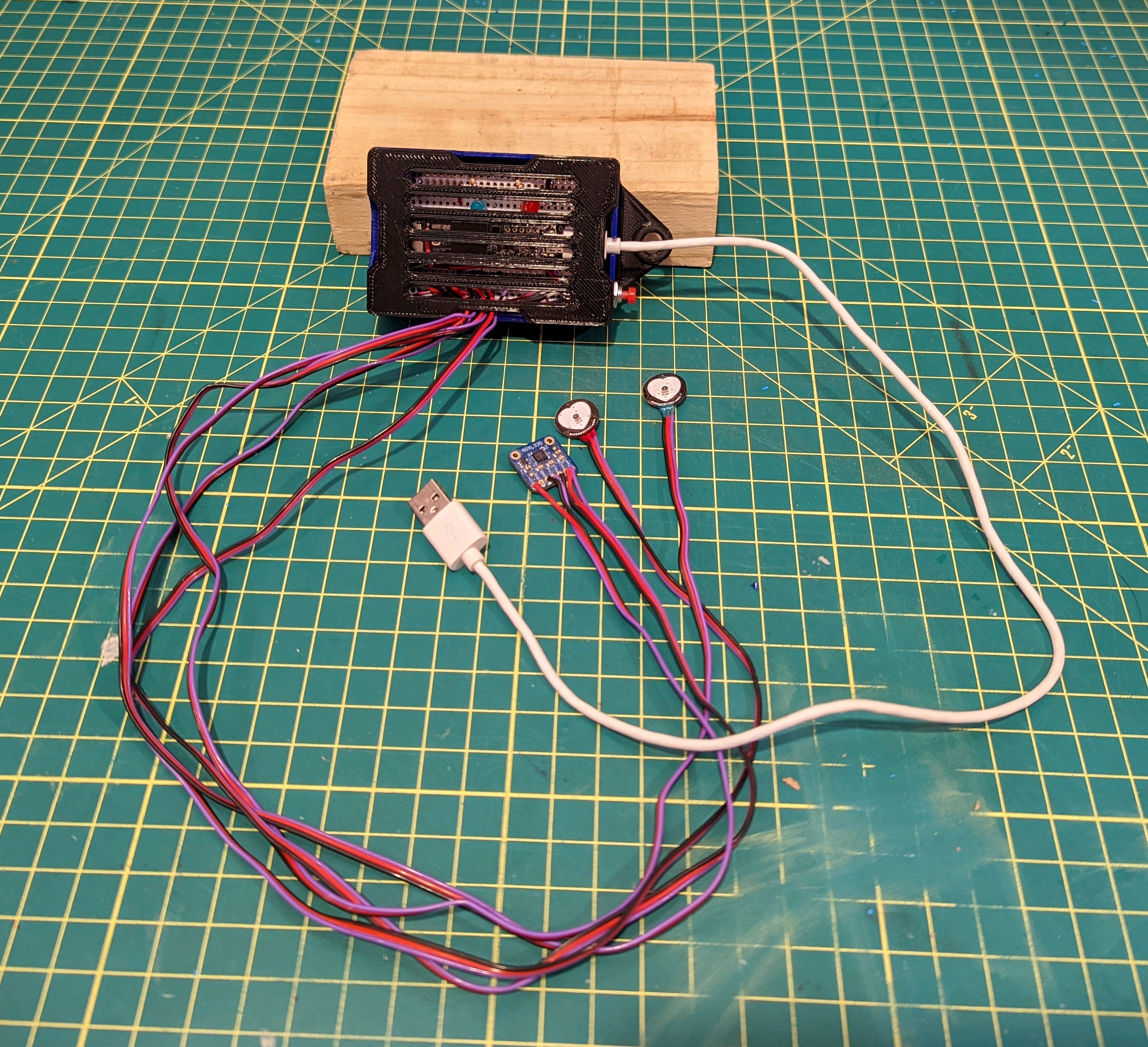
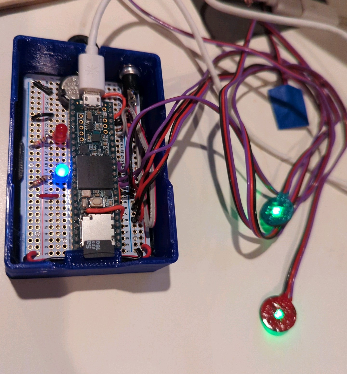
The blue LED pulses when it's idle, and then turns off and the red LED lights during recording. I modified the 1/2 size breadboard case files from Adafruit's PermaProto page. I gave it a bit more of a 'strain relief' on the USB cable, and a guide/support for the SD card removal/insertion. You can get the STL files from the 2022 branch of the git repo. I printed on my TAZ Mini 2 very successfully.
There's a coin cell to keep the Teensy 3.6 RTC alive. That's mostly for a future feature to make it more portable. I've rarely worked with the Adafruit solderable breadboard, but I gotta say, it's pretty nice and forgiving to work with !
boarded and boxed
![]()
conformal coating
![]()
-
rapid prototyping
03/11/2022 at 23:07 • 0 commentsThere are many things that make this project easy-er to build. That I happen to have a Teensy 3.6 in a drawer goes pretty far. I've also worked with the Arduino SD Fat library, in the past, to perform high speed card writes. Turns out Bill Greiman has updated the tools. His example will benchmark the write time (I added benchmarking the analog read time) and print out the stats of every record session including any overruns. It also has a section for acquiring data that reads analog pins. I'm using analog sensors, so that's not even a lift.
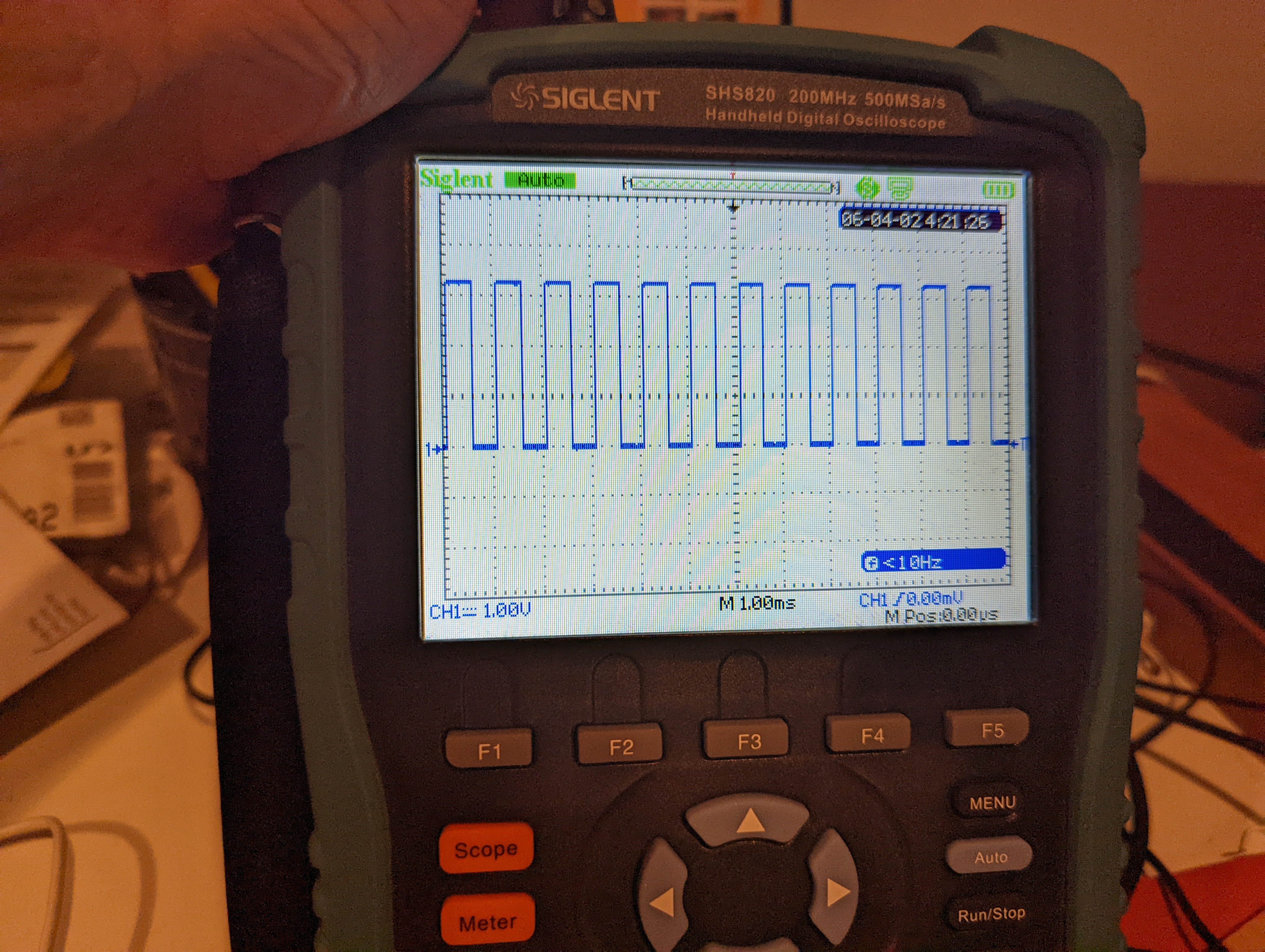
I have 5 sensor inputs. Two Pulse Sensors, and the three axis accelerometer. Acquiring and writing data always takes time, so it's important to verify a jitter 'free' sample clock. In order to do that, I'm toggling pin 24 on every sample. It should output a square wave that is half the sample rate. This is a 'sope of the pin.
Pin toggle on sample. should be 1kHz. SPS is 2kHz
![]()
Greiman's example also has a tool to convert the .bin file to .csv file. Dang.I think the interface will be primarily via computer serial port.
I want to add a button to at least initiate a record session.
Also, some LEDs to indicate that the thing thinks it knows what it thinks it's doing.
The good news is that I have all the parts laying around, and I can print a case in house.
More pics on the next log.
Hummingbird Heartbeats
I'm working with a bird researcher in Panama to use non-invasive techniques for measuring hummingbird heartbeats
 Joel Murphy