The IKEA Vindriktning has an unpopulated header for a 5 pin 1.25mm pitch connector. I've used a cheap MOLEX Picoblade knock-off connector from Aliexpress to populate it. I've also used a similar 3 pin connector for the PCB. I assume other 1.25mm pitched SMD headers will also work.
The PCB contains a header for a FTDI adapter and a boot pin. If you solder pins, make sure to remove them after flashing, because otherwise the board will not fit behind the screw holders in the Vindriktning case. I've personally used a test fixture with Pogo Pins for flashing as you can see in the gallery.
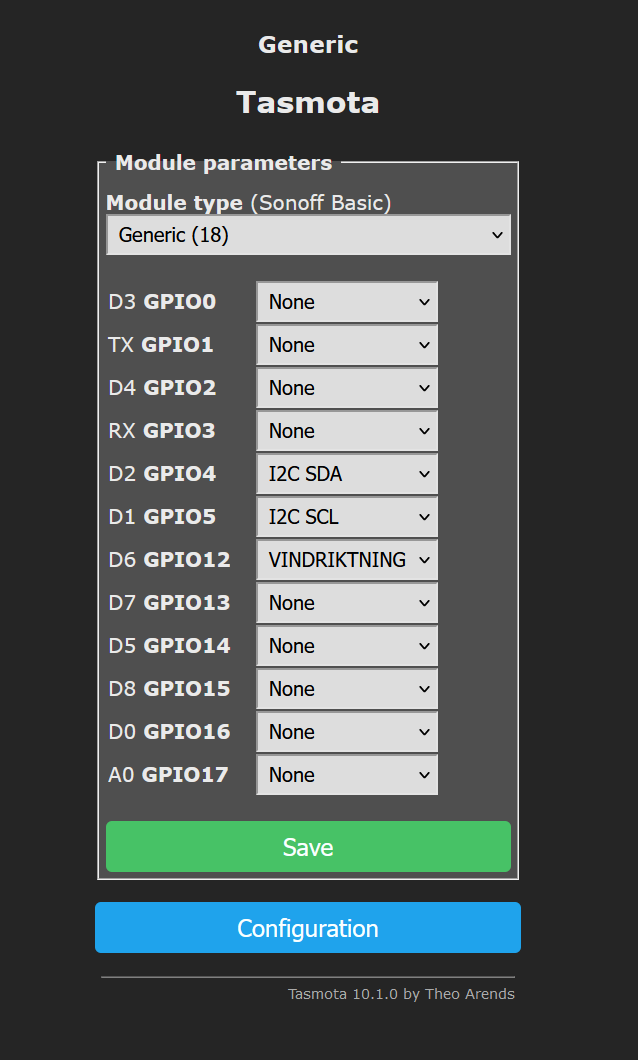
The BME680 is connected over I2C using GPIO 4 & 5, The IKEA Vindriktning is connected to GPIO 12.
The official Tasmota builds don't include the Vindriktning support. You need to either build your own or use the one I've compiled based on v10.1.0.
More information about building your own is available here: https://blakadder.com/vindriktning-tasmota/
After flashing you should configure the module as a Generic(18) module and specify the GPIO pins used like in the image

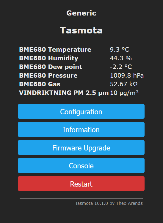
After a reset you should see the two sensors appear on the root page.

 Catalin Sanda
Nice! Thanks for sharing the firmware and PCB files. I agree that the design files are much more useful than just gerbers. I just wish I had seen your project before making my own PCB. In addition to a BME688 I also included a SGP30 and some WS2812s in my build.
Do you also have the impression that the temperature in the case is a few degrees above ambient? I was hoping the fan of the Vindriktning would circulate enough air to prevent that.