 Andrew Mitz
-
1Introduction and a very simple STEP 1
Introduction
This design uses rectangular brass plates cut from one long sheet. The amount of overlap between plates and the spacing between plates determine the capacitance. In this design, we use 3.06 mm thick brass nuts on threaded rod to space the plates apart. Thus, there are only 3 things to decide:
1. The length of the cut sheet
2. The number of brass nuts between sheets
3. The number of sheets that will be interdigitated with each other.A fixed capacitor to explain how it works
Let me explain the design using a fixed capacitor. My variable capacitor is actually simpler, but going over this design is helpful for explaining. This diagram shows the arrangement, dimensions and equation for a fixed capacitor. Some of the parts are in imperial units (e.g., inches), but I convert everything to millimeters to make the calculations easier.
![]()
The brass plates are held together by the threaded brass rods and insulators on the ends. (Plexiglas makes a great insulator.) Each brass plate has 2 holes. When the nuts are tightened, the structure is rigid. I will not discuss the relationship between breakdown voltage and plate spacing right now, but the spacing must be wide enough to tolerate the voltage you will be using. The capacitance is calculated as C (in the figure) times the number of sections of the capacitor. You can build a capacitor like this in an hour or two. It takes a hacksaw, drill, file and some wrenches.
Example
The figure has plates that overlap each other by 40 mm. Each plate is 50.8 mm wide. Thus, the area of each overlapping plate is 40 x 50.8 = 2032 mm2. The spacing is 3 nuts. Subtracting out the thickness of a plate, the nuts produce a gap between any two plates of 3.06 mm. The capacitor has 4 sections (4 gaps between plates).
Simplified equation
We can ignore the k value, since it is 1 for air. The value for ɛ is in Farads/meter. That is annoying. Fortunately, we can just throw away the exponent to get picoFarads (pF). ɛ = 8.85 pF/m. For mm, we divide by 1000:
ɛ = 0.00885 pF/mm. I will round it to 0.009 pF/mm. Now the equation is much simpler.
C = 0.009 * (Area / Distance) * sections (all in mm)
For this example with 4 sections
C = 0.009 * 2032/3.06 * 4
= 24 pF
A simple variable capacitor
To make a variable capacitor, you need a structure that lets you move one set of plates. In my design, I move one plate in between two fixed plates, in a simple linear fashion. Most traditional capacitors rotate. Mine is linear for two reasons:
1. A 3D printed frame makes assembly very easy.
2. The moving plate can have a soldered wire for a very low impedance connection. This is especially important for loop antennas.Here is the basic design of the linear capacitor. Note how simple it is. The fixed plates are spaced by 3 brass nuts. The sliding plate goes in between.
![]()
This design has 2 sections: section 1 is the capacitance between the sliding plate and the top plate, section 2 is the capacitance between the sliding plate and the bottom plate. The spacing is 3.06 mm, based on the thickness of these brass nuts and the thickness of the sliding plate. The plates are 50.8 mm wide (made from 2" wide brass sheet). Together, two sections gives you just under 0.3 pF for each mm of overlap. For my purposes, 40 mm overlap should provide 12 pF. In practice, the capacitance is a little higher.
Here is Step 1
- Cut 3 plates from the brass stock. The plates should be long enough for the 40 mm of overlap and to drill holes for the threaded brass support rods.
- Cut two lengths of threaded rod
- We will need 12 nuts for the fixed plates and two for the sliding plate.
The drawing shows two nuts for the sliding plate, but we will revisit how the sliding plate is attached.
-
23D printed frame
The 3D printed plastic holder is used to support the two fixed plates and provide a path for the sliding plate.
![]()
The STL file is in the Files section of this project. You can use it to make a 15 pF capacitor, or use it as a guide to designing your own.
After cutting and drilling the brass plates, the edges of the plates should be smoothed with a file. The fixed plates should mount easily on two threaded rods using the correct number of nuts to keep them spaced. The moving plate should ride easily along the guide. The mounting holes are for 8-32 screws. Mounting can be done with 2 side screws (there are two on either side) or the two front screws.
-
3Mechanical and electrical connections
The Files section has a STL file for printing a simple coupling. The coupler proved handy for attaching to a motor. However, almost any type of insulated coupling can be used. The coupler can be seen in the picture.
![]()
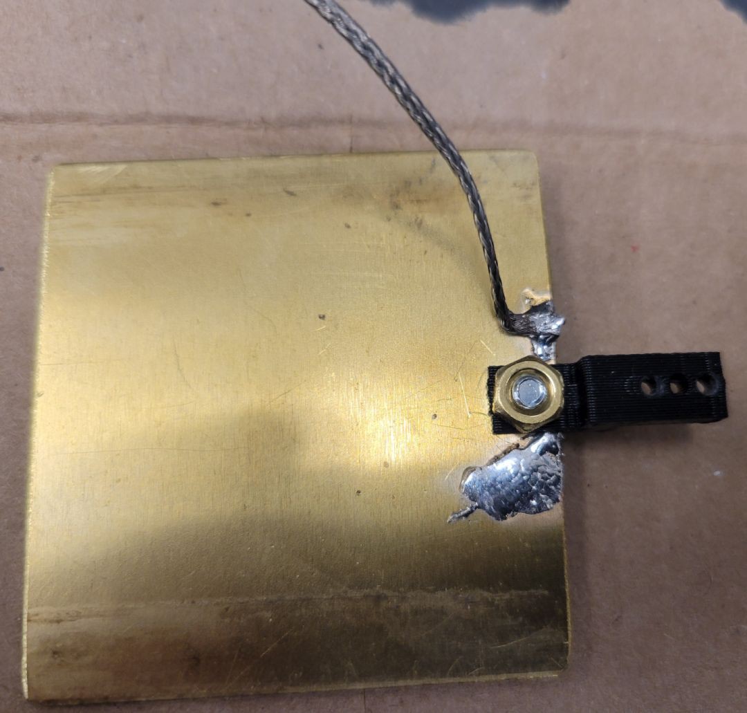
Electrical connections can be done in several ways. The fixed plates can be screwed to a solderless lug or soldered to a wire. It is best to solder the threaded rod when not assembled to the printed plastic piece. I opted to use wire braid for both the moving plate and the fixed plates. You can see the braid coming from the sliding plate in the picture above. You can see the braid on the fixed plate, below. The braid goes only a short distance to a heavy solid copper wire. This is inside of a tuning unit for a 100 W loop antenna, so low impedance connections are important.
![]()
The underside of the moving plate.
![]()
The braid is positioned so that it moves freely without touching other components when the moving plate is moved.
Construction is done!
The Easy Peasy variable capacitor is done! However, while you are here, we are going to dig deeper into testing and remote control.
-
4Testing
Capacitance testing
I tested the capacitance range in three ways.
1. Using a commercial LCR meter (Extech 380193)
2. Using a NanoVNA set to 30 MHz
3. Using an Array Solutions VNA (VNA-UHF )
Reliable measurements required careful calibration and testing. In all three cases the capacitance range was approximately 15 pF. Note, the minimum capacitance is about 5 pF.Voltage testing
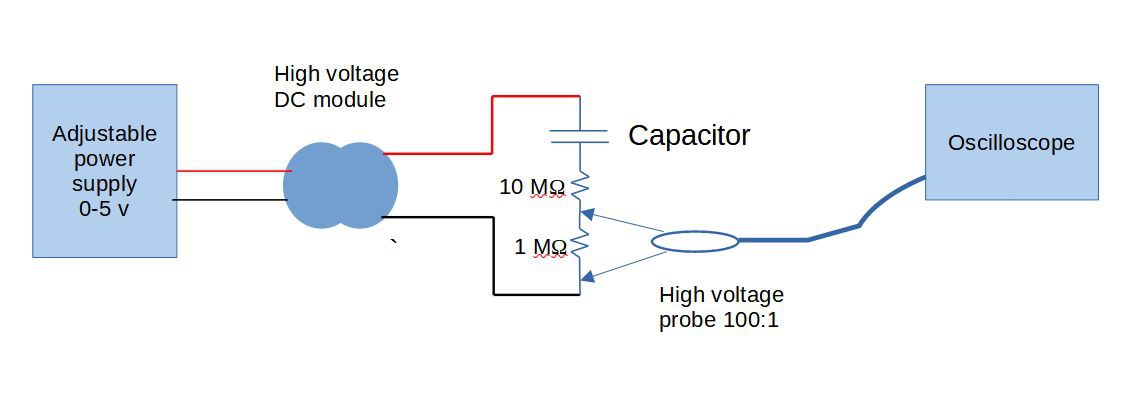
![]()
I considered different ways to do voltage testing. I settled on using a high voltage power module found on Amazon.com. There are many different modules. This one can throw quite a spark (B07JBKCCZ7 Ximimark DC 3V-6V to 400 kV Boost Step Up Power Module.) Note that these modules are easy to burn out. They are also high enough voltage to warrant great care with your test setup. They can also destroy your test equipment if you are not careful.
For the input power to the module I used a lab grade adjustable power supply with current regulation set to 2 A. I increased the voltage very slowly and always set the input back to zero after each test. The HV output of the power module has two leads. One goes to the capacitor. The other lead goes through a 1 MΩ/ 1 W resistor, then through a 10 MΩ / 5 W resistor, then to the other side of the capacitor. Both resistors are high voltage MOX-2 type resistors. (see diagram)
All testing was done on a 1/2" thick 12" x 12" Teflon sheet. The sheet makes sure that a voltage arc is not produced to the table top or any other nearby object.
I used a high voltage oscilloscope probe across the 1 MΩ resistor to monitor the current through the circuit (Cal Test GE3421 100:1 Passive Oscilloscope Probe).
To run a test, I increased the input voltage slowly from 2.5 volts until I heard a "snap" (arcing of the capacitor). At the moment of arcing, the resistance of the air is small compared to the 10 MΩ series resistor. Thus, the voltage across the 1 MΩ resistor can be used to estimate the voltage on the capacitor at the time of arcing. The two resistors form a voltage divider of 91:1. Thus, for each 1,000 volts on the capacitor, 91 volts are measured at the oscilloscope probe. The probe has a 100 MΩ input resistance, so it will not affect the measurement. Most oscilloscope probes have an attenuation of X10 and an input resistance of 10 MΩ. These can be used as long as you are careful not to exceed their safe voltage range. A X1 probe or direct connection to the oscilloscope is not advisable. Most oscilloscopes cannot tolerate 500 or 1,000 volts, which can easily happen if a spark crosses the 10 MΩ resistor. Note, I used a high voltage type resistors rated at 20 kV.
Adjusting for the 100:1 probe, for each 1,000 volts across the circuit, the oscilloscope reads 91 / 100 = 0.91 volts. The voltage reading will occur briefly at the moment of the spark followed by a decay on the scope display. A 4 volt peak reading indicates about 3,600 volts, which is the ballpark reading I got when testing. If you turn the input voltage up too high, you will get a nearly continuous spark on the capacitor. The capacitor will act something like an arc voltage regulator. I advise against doing this unless you want to jam your housemate's cellphone and carbonize the brass plates.
-
5Motor drive
The basic capacitor is done. This next section is how I built a motor drive to remotely position the capacitor.
I decided to use a DC motor. Perhaps a stepper is a better idea, but for now I like this design. The motor I chose is overkill. It was originally selected for the more heavy-duty task of turning a large tuning capacitor. The advantages of this motor are that it is well-built and has a 488:1 gear system to make it easy to control at low speeds. The motor is a Pololu model 3485 (488:1 Metal Gearmotor). I use an off-the-shelf rack and pinion gear. (McMaster-Carr 2662N53 20 Degree Pressure Angle Gear Rack, 2662N16 20 Degree Pressure Angle Plastic Gear.) Together these cost under $10. The rack is easy to cut and drill as necessary. The rack is a 32 pitch (per inch) and the gear is 32 teeth, so one rotation gives 1 inch of motion.
The motor and gears are mounted in a 3D printed housing. See the Files section for the STL print file. The motor mount has a set of tapped #8 screw holes to make mounting easy. It was not difficult to line the rack up with the linear capacitor. I did slot one of the screw holes for mounting the capacitor. That gave me an small angle adjustment to help with the alignment. The motor is designed for 12 v. It can be run more slowly down to 6 v. However, I use pulse-width modulation (PWM) to control motor speed.
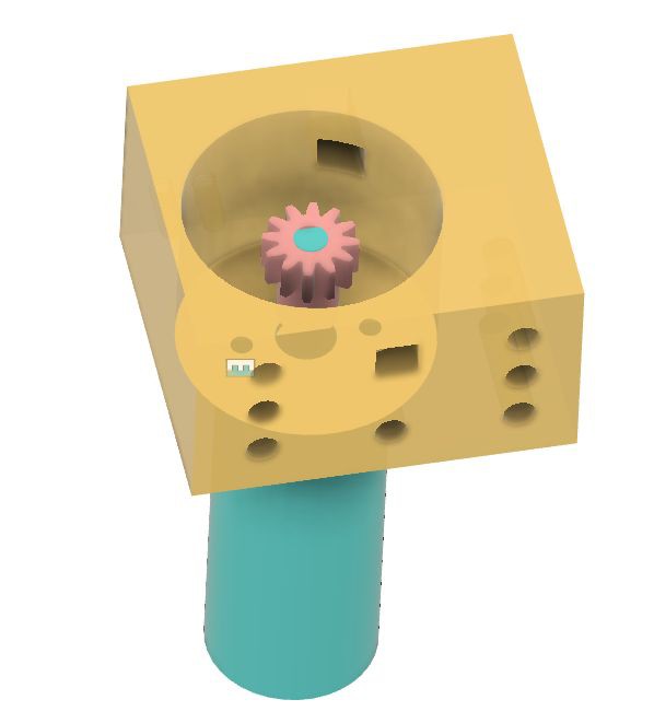
Here is a CAD drawing of the motor, mounting block and gear. Note the 7 possible mounting points. The design has provision for mounting a microswitch (snap action switch) to detect the position of the rack when it is at about 65% of full range. I call this a limit switch.
![]()
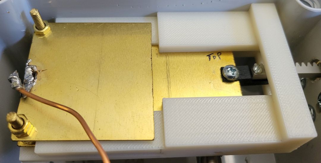
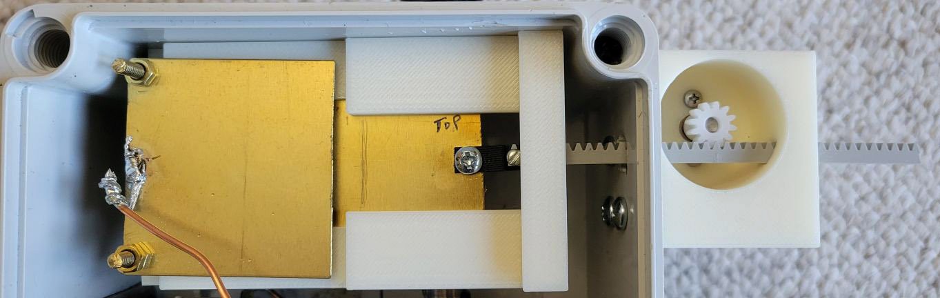
Here is the motor mount in place, aligned with the linear capacitor. The rack sticks out on the right side. The limit switch uses this protrusion to sense the capacitor position.
![]()
-
6Arduino motor controller (hardware)
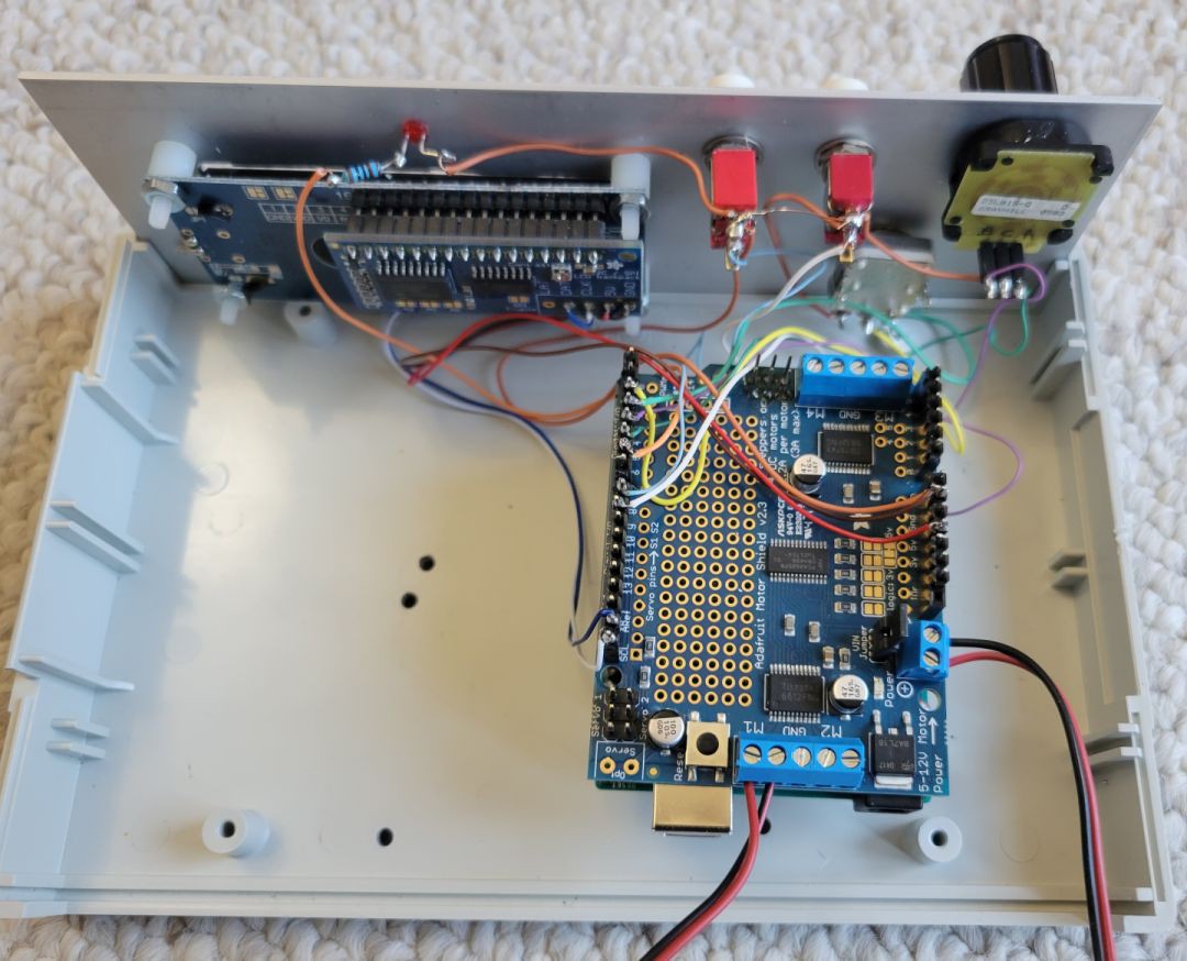
The controller is an Arduino Uno with an Arduino Motor Control Shield V2.3. (see photo) Two shaft encoders set speed and position. A pushbutton sets the zero position. A 16 character x 2 line LCD provides numeric feedback. The Motor Shield and motor run on 12 V supplied by the red and black wire pair on the right side of the photo. That same 12 V can be used by the Arduino, but I don't like running the Vin of the Arduino Uno at 12 V. Arduino voltage regulators run warm at 12 V. I mounted a 12 V to 9 V DC-DC converter/regulator (v7809-500) on the Motor Shield board to lower the input voltage going to the Arduino Vin terminal. There is a jumper on the Motor Shield and the regulator simply replaces the jumper.
The second red and black wire pair go to the motor. One more lightweight wire pair is needed for the limit switch.
The hardware connections for the Arduino are:
D0/RxD dig pin 0 Reserved for serial monitor
D1/TxD dig pin 1 Reserved for serial monitor
D2 dig pin 2 Frequency shaft encoder up
D3 dig pin 3 Frequency shaft encoder dn
D4 dig pin 4 Rate shaft encoder up
D5 dig pin 5 Rate shaft encoder dn
D6 dig pin 6 Ready LED
D7 dig pin 7 Limit switch
D8 dig pin 8 Stop pushbutton
D9 dig pin 9 Capacitor resetA4/SDA analog pin 4 I2C SDA
A5/SCL analog pin 5 I2C SCLI2C addresses:
0x70 LCD Backpack (default)
0x60 Motor Control Shield (default)![]()
The Arduino program is still in development. My goal is to remotely adjust the frequency of a loop antenna. Here is how the current version of the software operates.
The idea is to adjust a rotary encoder to a specified value of capacitance. The software monitors this "desired" capacitance value and automatically adjust the capacitor to match this value.
Thus, the operator actually has two encoders. One sets the desired capacitance. The other controls the tuning rate. There are 9 different step sizes (range 0.4 pF per step to 10.0 pF per step). In practice, not all step rates are used when tuning. The fine control of a loop antenna needs very small steps on high frequency bands, whereas larger steps make more sense at lower frequencies.
Whenever the desired value does not match the current capacitance position, the motor begins moving the capacitor from its current value towards the new value. The motor moves quickly at first, then steps down in speed as it approaches the desired value. The motor movement is constantly updated by any change in the target value.
Absolute capacitance is really not important for a loop antenna like mine. What is important is getting the capacitor adjust for the lowest SWR. There is a Reset pushbutton that will retract the capacitor to it's minimum position. There is also a Stop pushbutton. For tuning an antenna, I reset the capacitor, turn the capacitance setting to get the motor started, then watch the SWR. I can either adjust the desired capacitor value to find the best SWR, or just hit the Stop button when I am satisfied.
The 2 line by 16 character LCD reports the desired capacitance and tracks the motor movement towards that value. The LED is ON whenever the motor is active.
-
7Arduino motor controller (software)
I am happy to share my code. It is written in an unholy combination of c and c++ using the Arduino IDE. At this writing it has about 600 lines. This is a project in development. The current version has been highly modified since the last test, so I am not going to post it here. I will touch on some aspects of the code that programmers might appreciate.
I am using these libraries for the Arduino Uno and Motor Shield v2.3. Be sure you install the proper Adafruit_MotorShield library.
#include <Wire.h>
#include <Adafruit_MotorShield.h>
#include "Adafruit_LiquidCrystal.h"
#include "Arduino_DebugUtils.h"
#include <RotaryEncoder.h>
Based on some testing, I have a table of what PWM settings correspond to matching rates of change in capacitance (pF/sec).
const unsigned int PWM[]={0,1,2,4,8,16,30,61,122,244};
const float pf_per_sec[]={0,.04,.08,.16,.33,.66,1.23,2.5,5,10};
When I write embedded code I like to use my own background timers. These are usually timers that count down to 0 in seconds or milliseconds. I take this approach because I write for different hardware platforms. Some have great built-in timers, while others are less capable. Writing my own timers gives me consistency in my code.
For this simple controller I use micros() to update timers that have a 2 ms tic. They are defined here (yes, I could use enum type)
// Timers  These run at 2ms per count
unsigned long start_2ms;
const int MAX_2ms_TIMERS = 6;  // room to grow
unsigned int Timer_2ms[MAX_2ms_TIMERS]; // create timers
const int LCD_UPDATE_TIMER = 0;
const int MOTOR_MOVE_TIMER = 1;
const int LED_TIMER        = 2;
const int HEARTBEAT_TIMER  = 3;
The Arduino loop() updates the clocks every 2 ms:
  // Check 2ms clock/timers
  time_difference = micros()-start_2ms;
  if ( time_difference >= TIC) {
     start_2ms = micros(); // restart timer
     for (int tc=0; tc < MAX_2ms_TIMERS; tc++)
        Timer_2ms[tc] = (Timer_2ms[tc] == 0) ? 0 : Timer_2ms[tc]-1;
  }
Update of the timers occurs at the top of loop() in a section I call "services". Updates of the encoders and their immediate effect (e.g., change in the target capacitance) occur every time through the loop. Other events are paced by these two timers:
200 ms Translating encoder change to new target capacitance
100 ms Update LCD (one or both lines)
As noted above, the change in target capacitance is not fully synchronized with the movement of the capacitor. Setting the target capacitance is the operator's activity. She can select the step size and choose any value in the range. In the background, the program looks at the difference between the current capacitance and the desired value. Using the rate table (see above), the program selects the fastest rate that will not overshoot the target and programs the PWM to that rate (in the correct direction). The motor continues at this speed until the next update. In the absence of further changes by the operator, the motor speed is stepped-down as the target capacitance is approached. This method produces a rather slow final approach to the target. The approach speed can be improved simply by not using the smallest steps. After testing this software on the fully operational loop antenna, there may be "best" settings for each ham radio band. If that is the case, the rate control will likely be repurposed as a band select switch.
Eazy Peasy High Voltage Variable Capacitor
3D printed fixed and variable capacitors. Simple theory, simple methods. But don't build it this way! See why by reading the project.
Discussions
Become a Hackaday.io Member
Create an account to leave a comment. Already have an account? Log In.