Close
0%
0%

Smart Apartement Ventilation

Conversion of the existing apartment ventilation. Implemented with an ESP8266.

Similar projects worth following
My apartment ventilation is not particularly smart. I can only use it to set the level of
ventilation and initiate shock ventilation (ventilate at the highest level for 30 minutes).

There has to be a smarter way.
I want to achieve the following:
- Ventilate when bad air
- ventilate automatically in the morning
- ventilate automatically before going to bed
- ventilate if it's too hot in summer
- must be removable
- must not be soldered

I do this as follows:
- ESP8266 which relay control which then press the buttons
- ESP8266 must be controllable via HTTP REST
- DC-DC StepDown converter (because 12V is present in the original controller)

After some thought, it would be best if I had the following control
options:
- set level 1
- set level 2
- set level 3
- ventilate for 30 minutes


The ESP8266 runs with the ESPEasy firmware. With this, simple rules can be created to control the GPIO pins. You can find the rules for the ESPEasy in the "files" section from this project.

// NOTES

// PINS

6 gpio12    -> button +
7 gpio14    -> button -

/TEST RELAIS
http://IP-ESP8266/control?cmd=GPIO,13,1
http://IP-ESP8266/control?cmd=GPIO,14,0

// COMMANDS
/SET STAGE
http://IP-ESP8266/control?cmd=event,stage0
http://IP-ESP8266/control?cmd=event,stage1
http://IP-ESP8266/control?cmd=event,stage2
http://IP-ESP8266/control?cmd=event,stage3

/VENTILATION FOR 30 min.
http://IP-ESP8266/control?cmd=event,ventilation

VOC_housing_lid.stl

Standard Tesselated Geometry - 182.60 kB - 03/17/2022 at 21:12

Download

VOC_housing.stl

Standard Tesselated Geometry - 183.19 kB - 03/17/2022 at 21:12

Download

esp_easy_rules.txt

Rules for ESPEasy

plain - 2.60 kB - 03/11/2022 at 21:50

Download

  • 1 × Wemos D1 mini
  • 1 × DC-DC Step Down module

  • VOC Sensor

    Nik Reitmann03/17/2022 at 21:12 0 comments

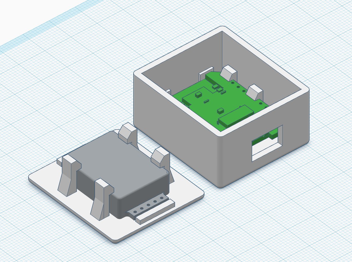
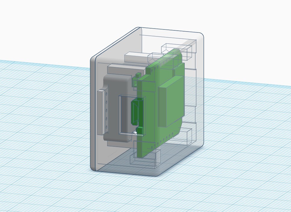
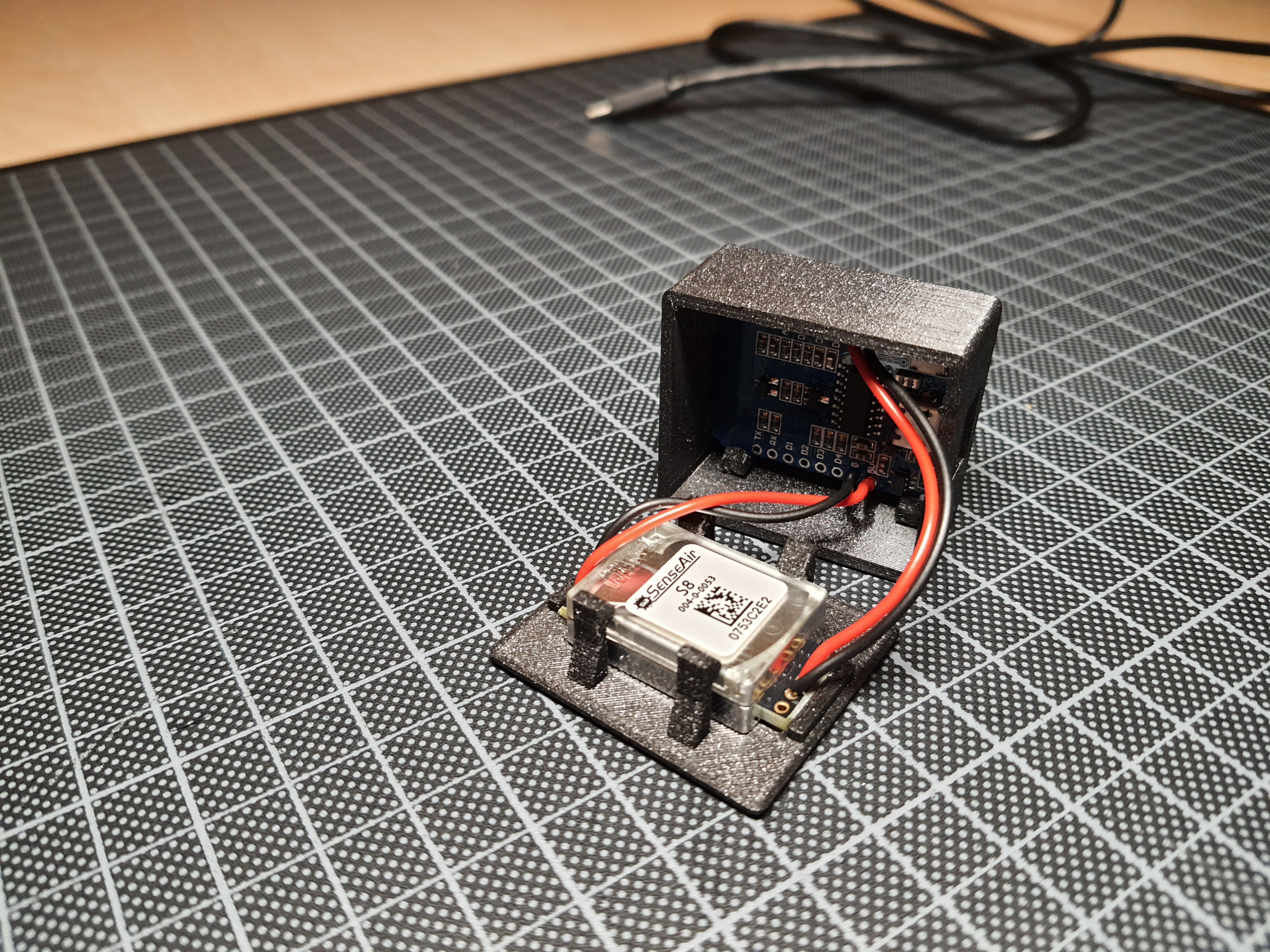
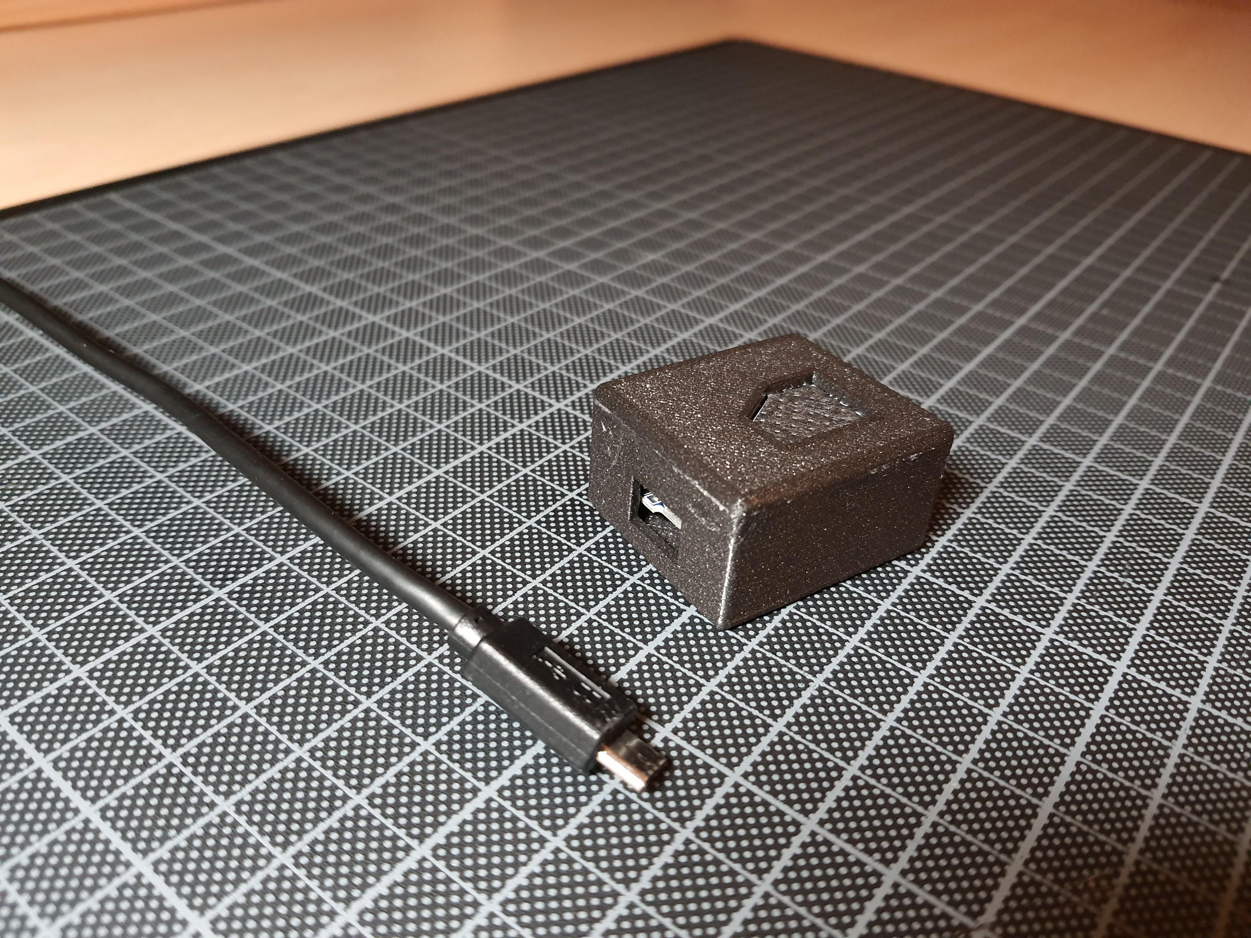
    Today the Sensair S8 from Aliexpress arrived. I have now drawn a housing for the sensor with another ESP8266 (Wemos D1 mini). The sensor gives me the CO2 value in ppm, with this value I control my ventilation.

    Housing:

  • Testing

    Nik Reitmann03/11/2022 at 22:30 0 comments

  • Write some code for the ESP

    Nik Reitmann03/11/2022 at 22:13 0 comments

    Now I have to write some code. After some thought, it would be best if I had the following control
    options:
    - set level 1
    - set level 2
    - set level 3
    - ventilate for 30 minutes


    I noticed that 100ms is not enough to press the button. With a value of 500 ms, pressing the keys works stable.

    The following is the ventilation level 2 code as an example:

    // STAGE 2
    On stage2 do
    
      // 4 X CLICK DOWN
      Pulse,14,1,500
      gpio,14,0
      Pulse,14,1,500
      gpio,14,0
      Pulse,14,1,500
      gpio,14,0
      Pulse,14,1,500
      gpio,14,0
      Pulse,14,1,500
      gpio,14,0
    
      // 2 X CLICK UP
      Pulse,12,1,500
      gpio,12,0
      Pulse,12,1,500
      gpio,12,0
    
      //RESETGPIO
      gpio,12,0
      gpio,13,0
      gpio,14,0
    
    endon

    Now I can integrate the whole thing into my smart home and control it as I like. Unfortunately, I
    haven't received the VOC sensor from Aliexpress yet, so I have to wait with the VOC-controlled
    ventilation.


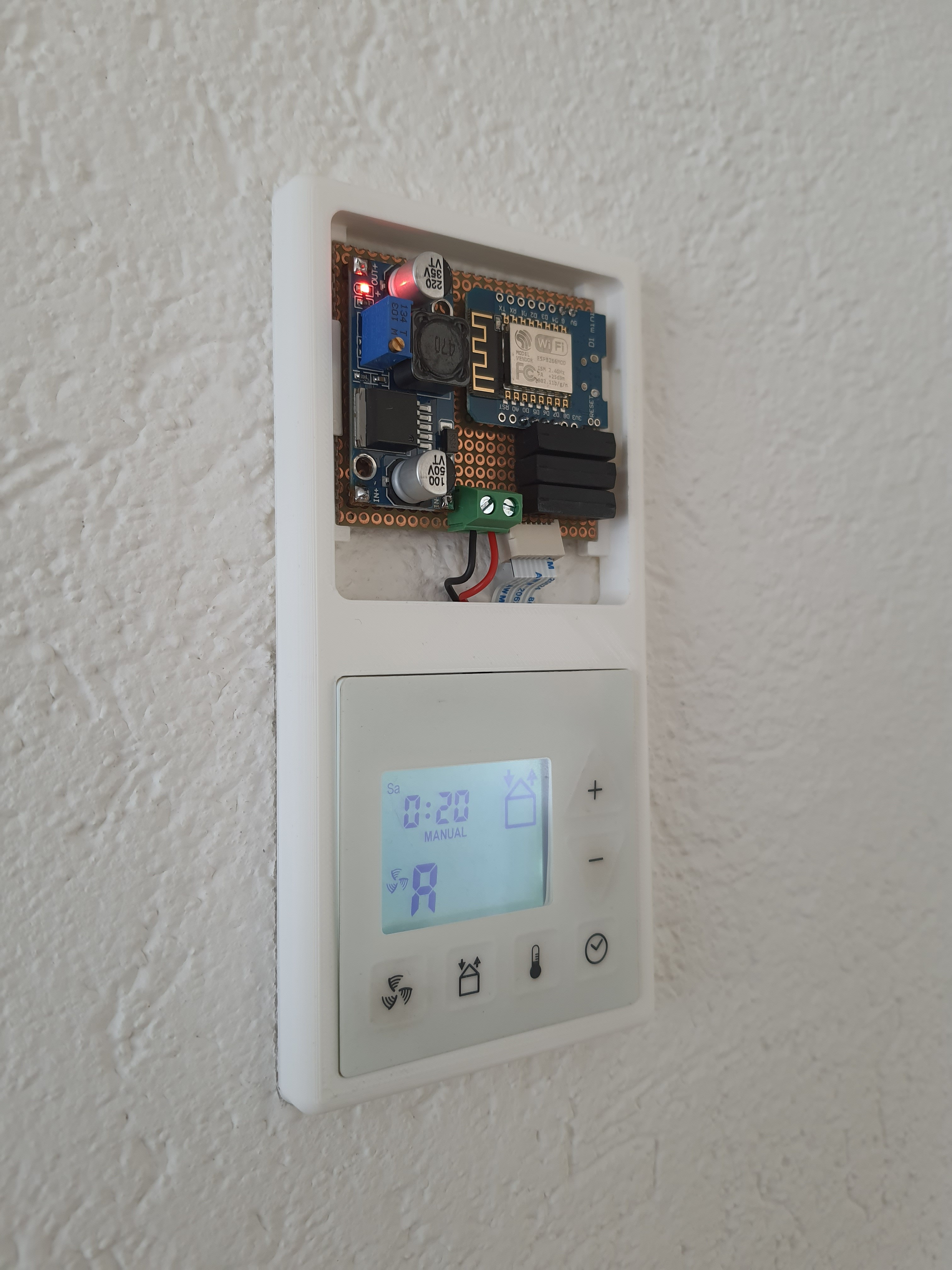
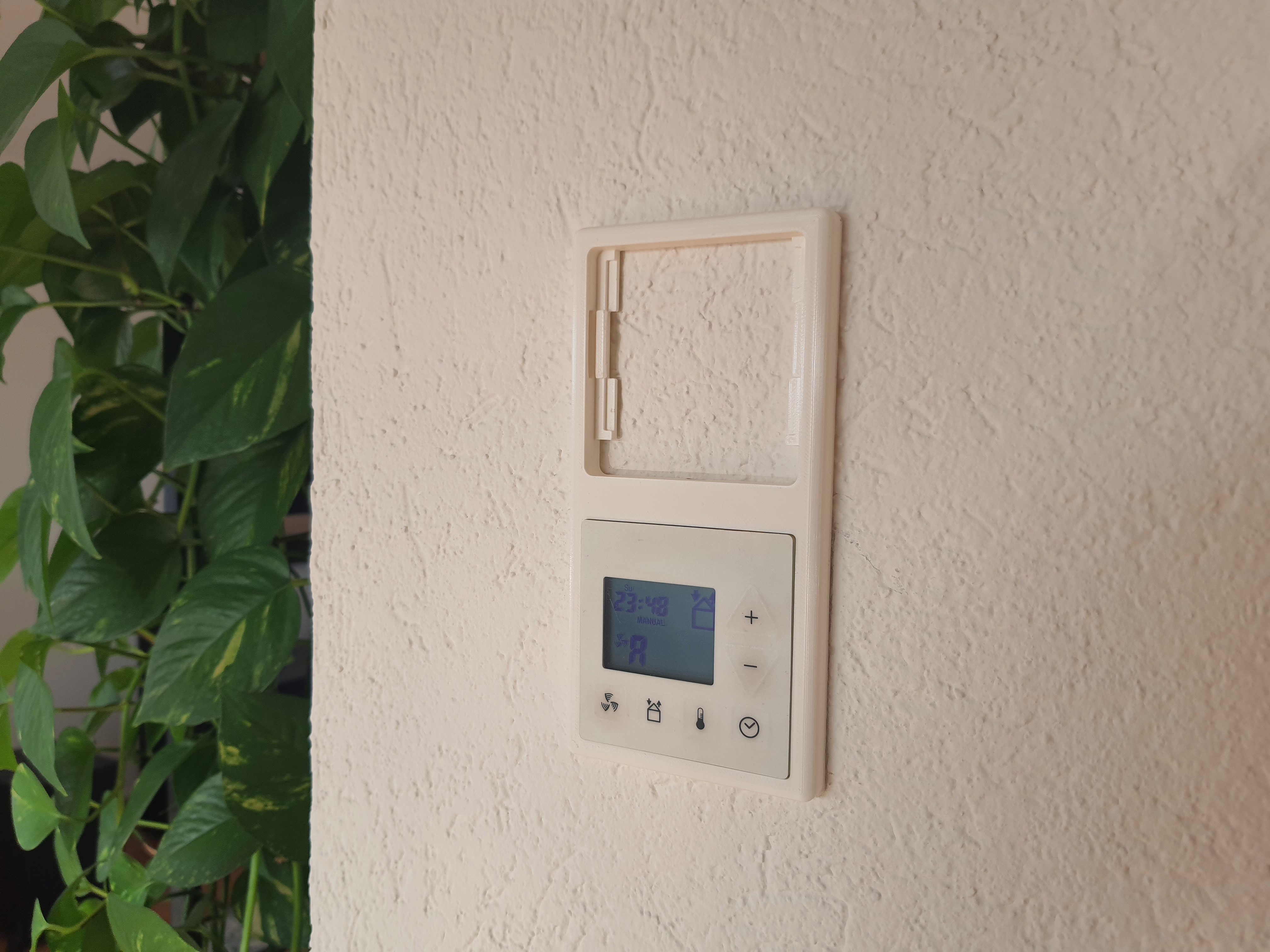
  • Housing mounted and ESP8266 running

    Nik Reitmann03/11/2022 at 22:09 0 comments

  • Install and connect

    Nik Reitmann03/11/2022 at 22:08 0 comments

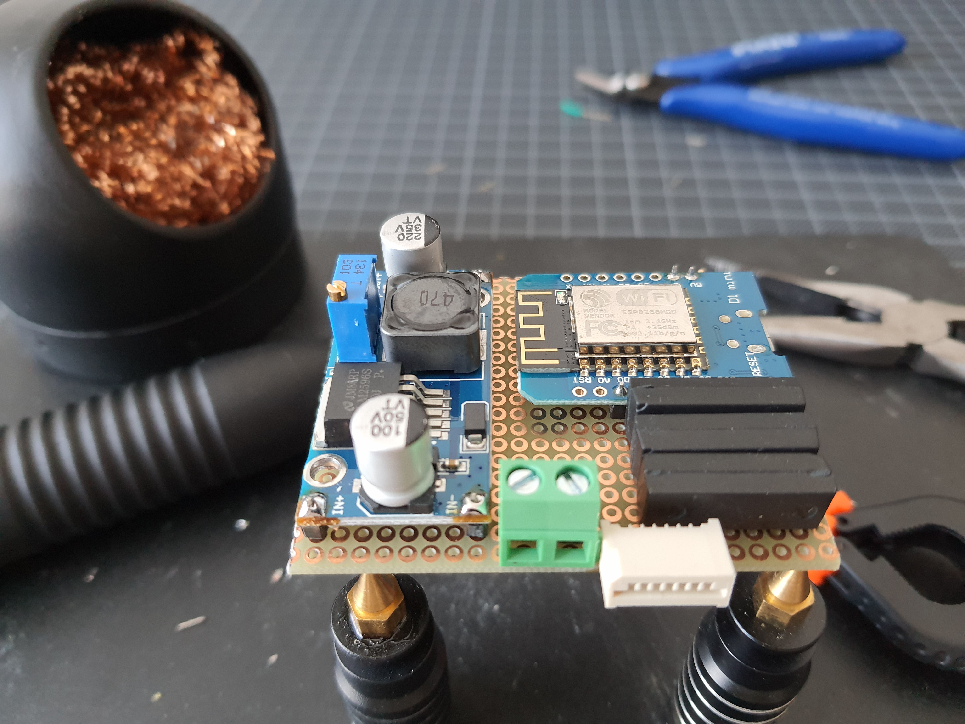
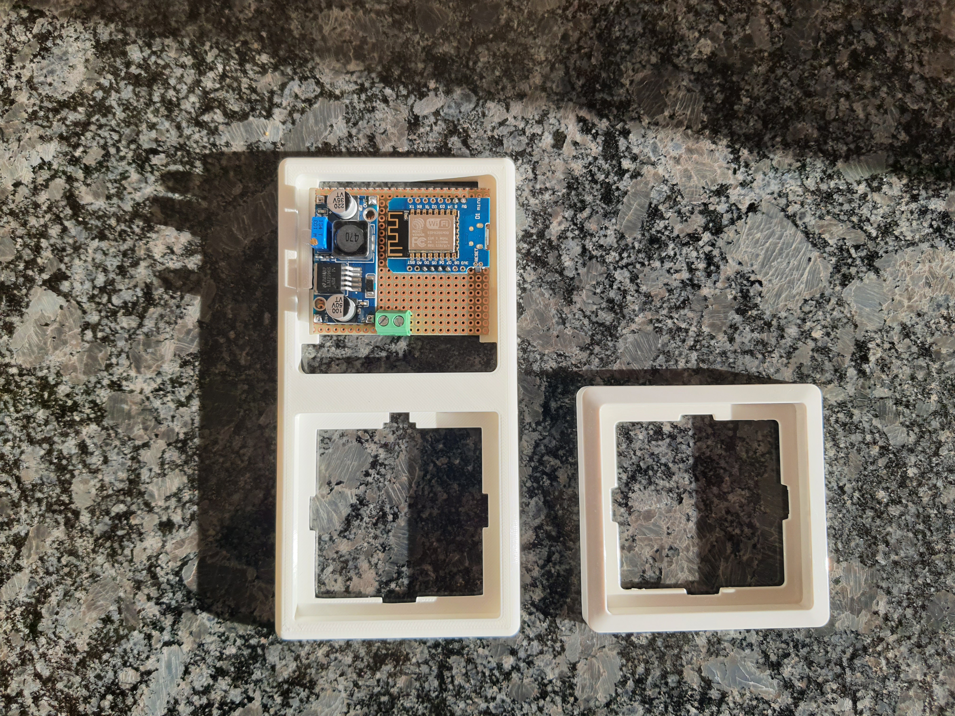
  • Building the PCB

    Nik Reitmann03/11/2022 at 22:07 0 comments

    Now I build the PCP. Left: DC-DC StepDown converter, top right: ESP8266 (Wemos D1 mini), bottom
    right: SSR relay

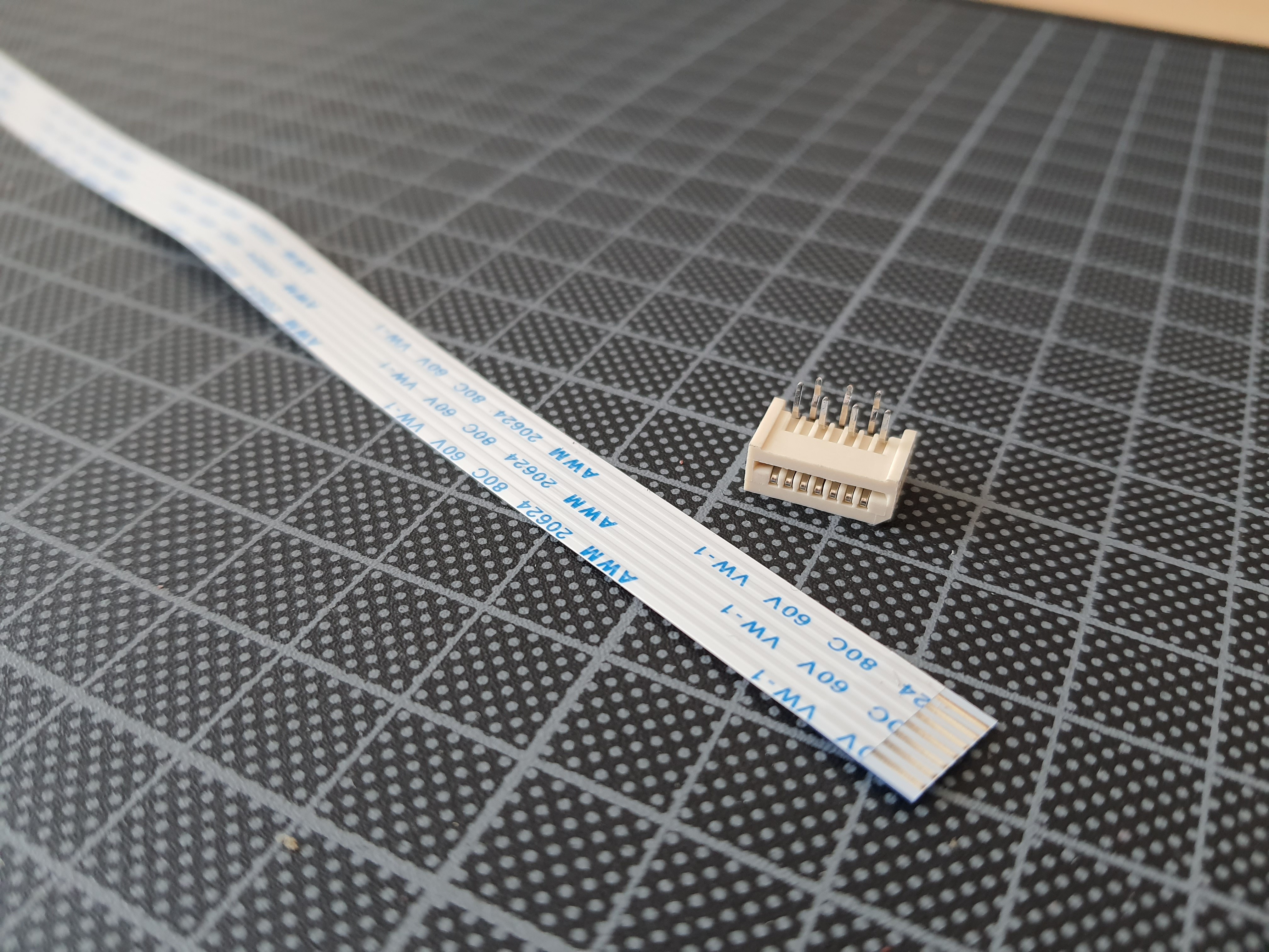
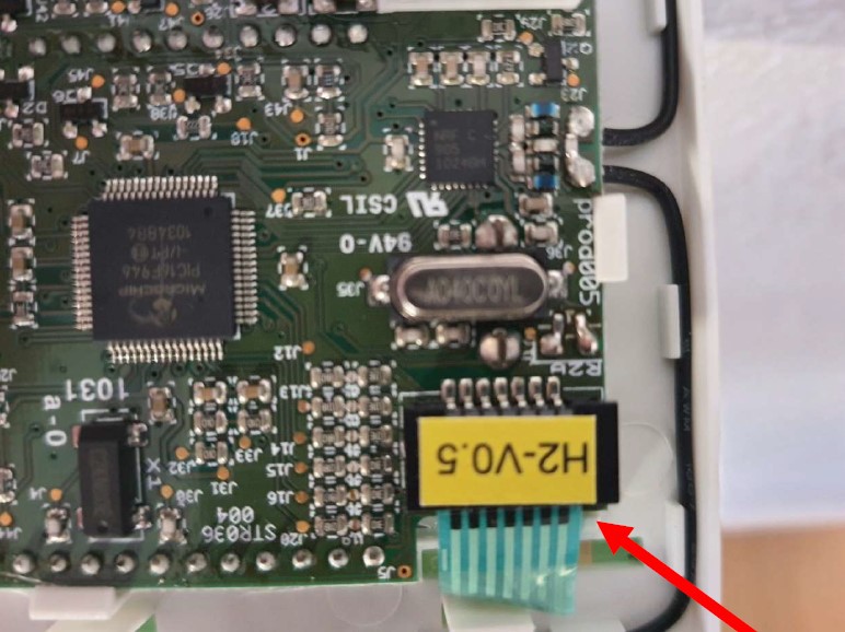
  • successfully found the flat cable

    Nik Reitmann03/11/2022 at 22:06 0 comments

    Found, apparently the Renault Megane has installed the same cable for the airbag

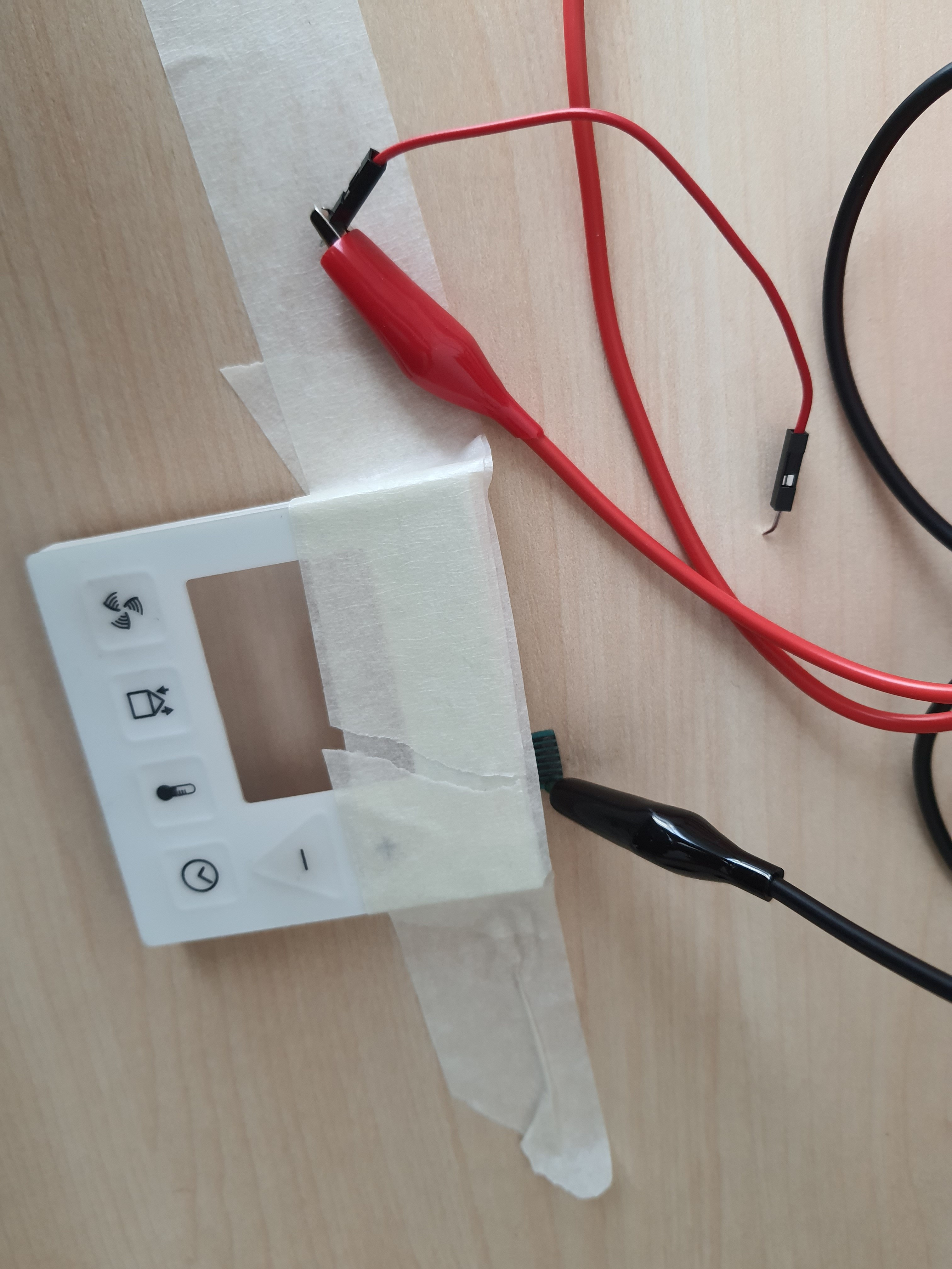
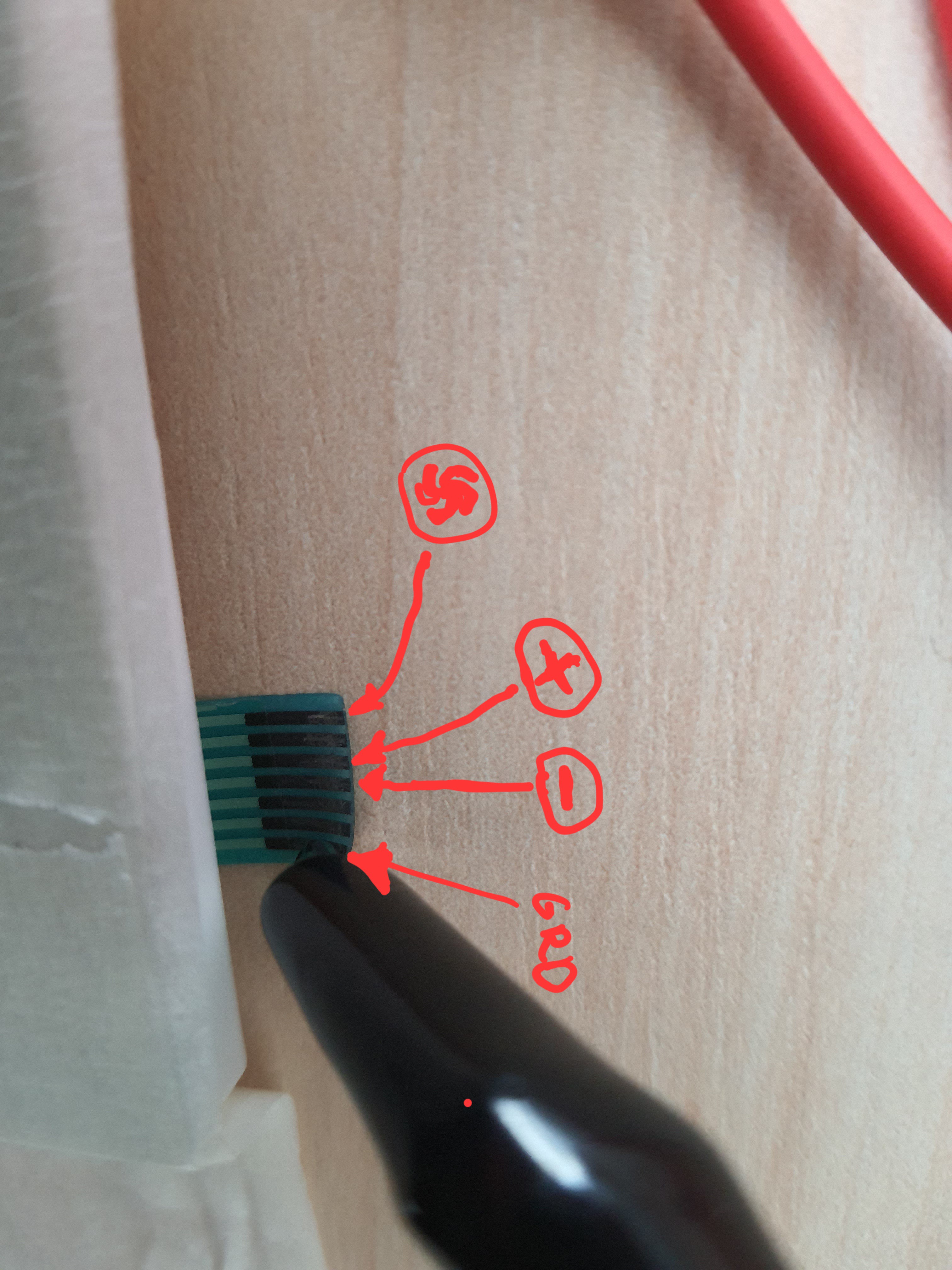
  • measuring the front panel

    Nik Reitmann03/11/2022 at 22:03 0 comments

    Now I take a closer look at the original device. The panel buttons are connected to this ribbon cable. I measure out which pin is for which button. Now I have to find the same ribbon cable with connector on aliexpres...

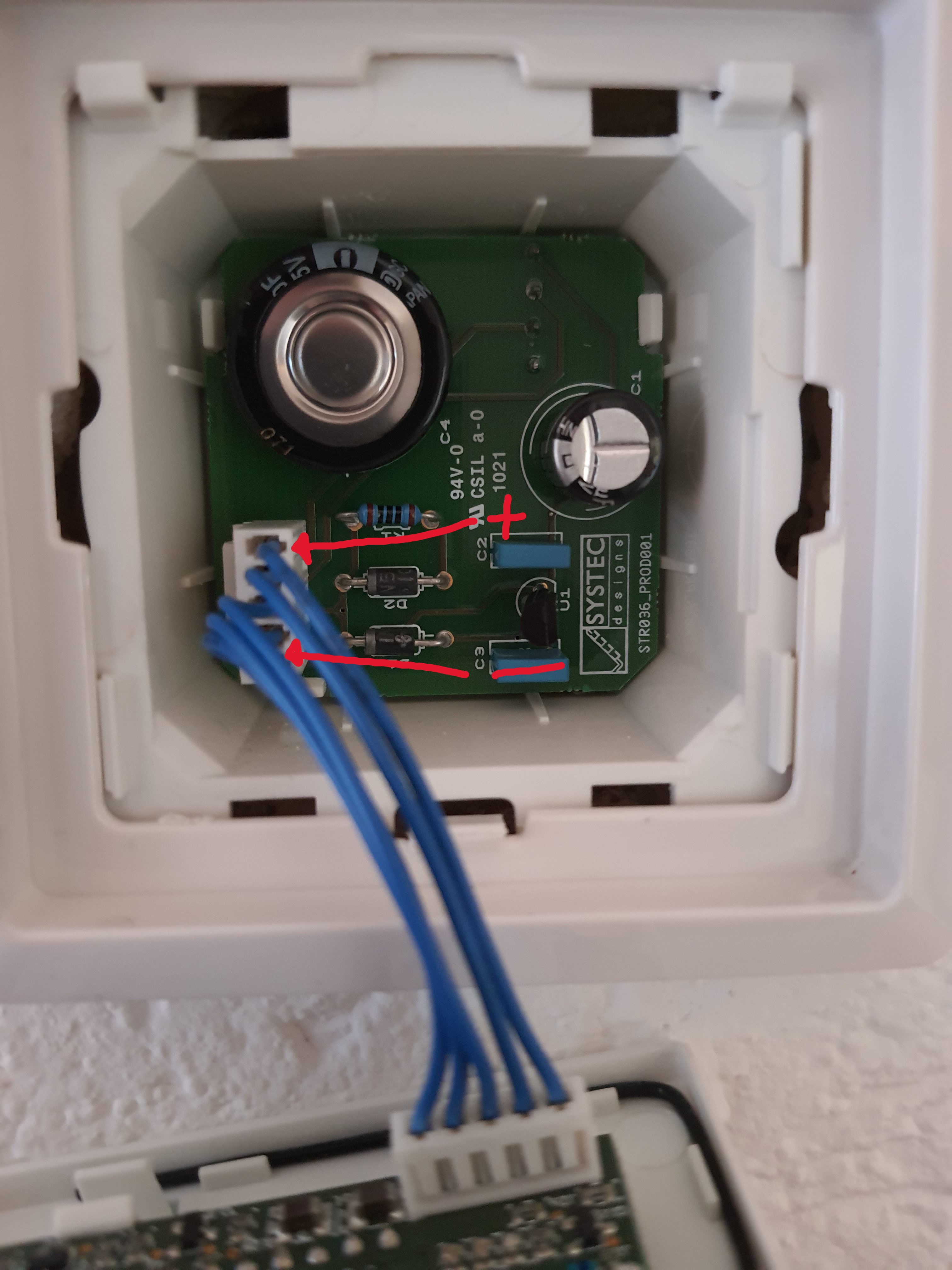
  • Power search

    Nik Reitmann03/11/2022 at 21:57 0 comments

    Because I don't want to have an extra power supply, I check whether I already have direct current somewhere in the housing. I'm lucky, the original control is operated with 12V. 


    That means I also have to use a DC-DC StepDown converter so that the ESP8266 can be supplied with 5V.

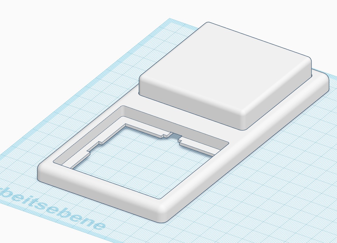
  • Housing

    Nik Reitmann03/11/2022 at 21:53 0 comments

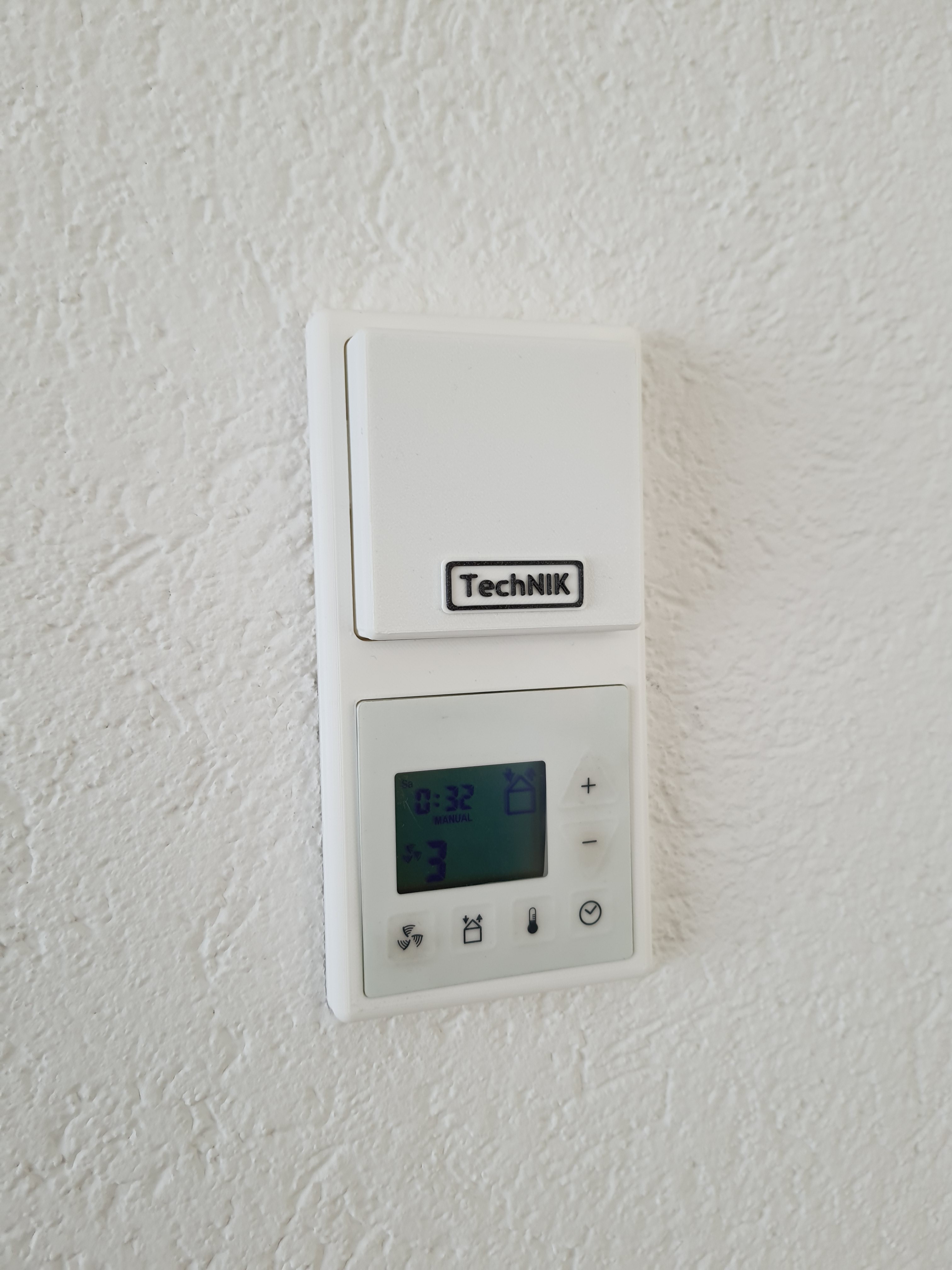
    First, I drew the original housing so that I could put my own housing above where I would then install

    my PCP with the ESP8266.

View all 10 project logs

Enjoy this project?

Share

Discussions

apknike wrote 05/20/2022 at 23:54 point

Gute idee!  I am working on something similar at my home, i take idea from https://apknike.com/gbwhatsapp-apk/

  Are you sure? yes | no

theWookie wrote 03/15/2022 at 15:25 point

our of curiosity what program did you use to draft the housing? 

  Are you sure? yes | no

Nik Reitmann wrote 03/15/2022 at 15:57 point

I drew this with TinkerCAD "tinkercad.com". It's free and you can use it in your browser. It is a Constructive solid geometry (CSG) CAD. If you have a project with moving parts it's unusable, then I use FreeCAD.

  Are you sure? yes | no

kc8kva wrote 03/14/2022 at 12:38 point

Gute idee!  I am working on something similar for my lab in the basement.  For me, it is repurposing some 12V computer fans with a PWM to control the speed.  Sehr Interessant!

  Are you sure? yes | no

Johannes Franke wrote 03/14/2022 at 10:47 point

I wondered about that, too. Any pass-through there? By the way, I think I have seen what could be two antenna wires on the inside of the front panel. If these devices are radio-controllable, you could find an even more invisible way of commanding them. But anyway, nice idea and well done! Please share the manufacturer and model, maybe we can find out how this works with RF control. Cheers, have a nice day!

  Are you sure? yes | no

Nik Reitmann wrote 03/14/2022 at 10:57 point

Thank you, I saw the antennas too. But I don't have a remote control, and radio protocols are not my forte :-)

  Are you sure? yes | no

Mihai Zaharie wrote 03/14/2022 at 10:22 point

How did you connect the ribbon cable to both the buttons and your controller? 

  Are you sure? yes | no

Nik Reitmann wrote 03/14/2022 at 10:58 point

I simply plugged the flat cable into the existing connector. A Y-splitter was not necessary (but originally intended)

  Are you sure? yes | no

Johannes Franke wrote 03/14/2022 at 12:46 point

ah, so the buttons no longer work?

  Are you sure? yes | no

Nik Reitmann wrote 03/14/2022 at 12:55 point

I put both cables, the original and mine, in the connector. The buttons can also be used.

  Are you sure? yes | no

Similar Projects

Does this project spark your interest?

Become a member to follow this project and never miss any updates