Xtreme Tech
-
Gyro Sensor
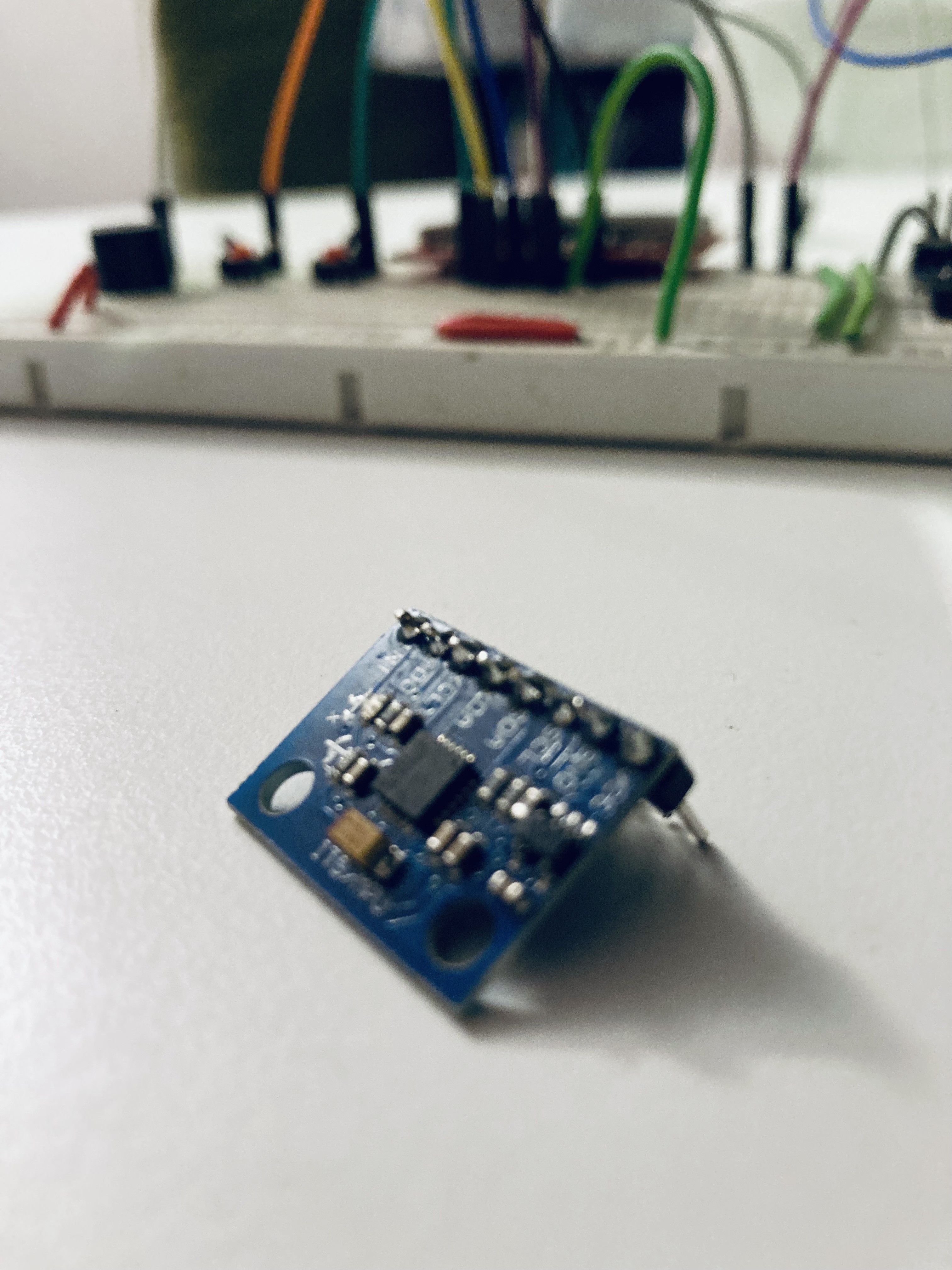
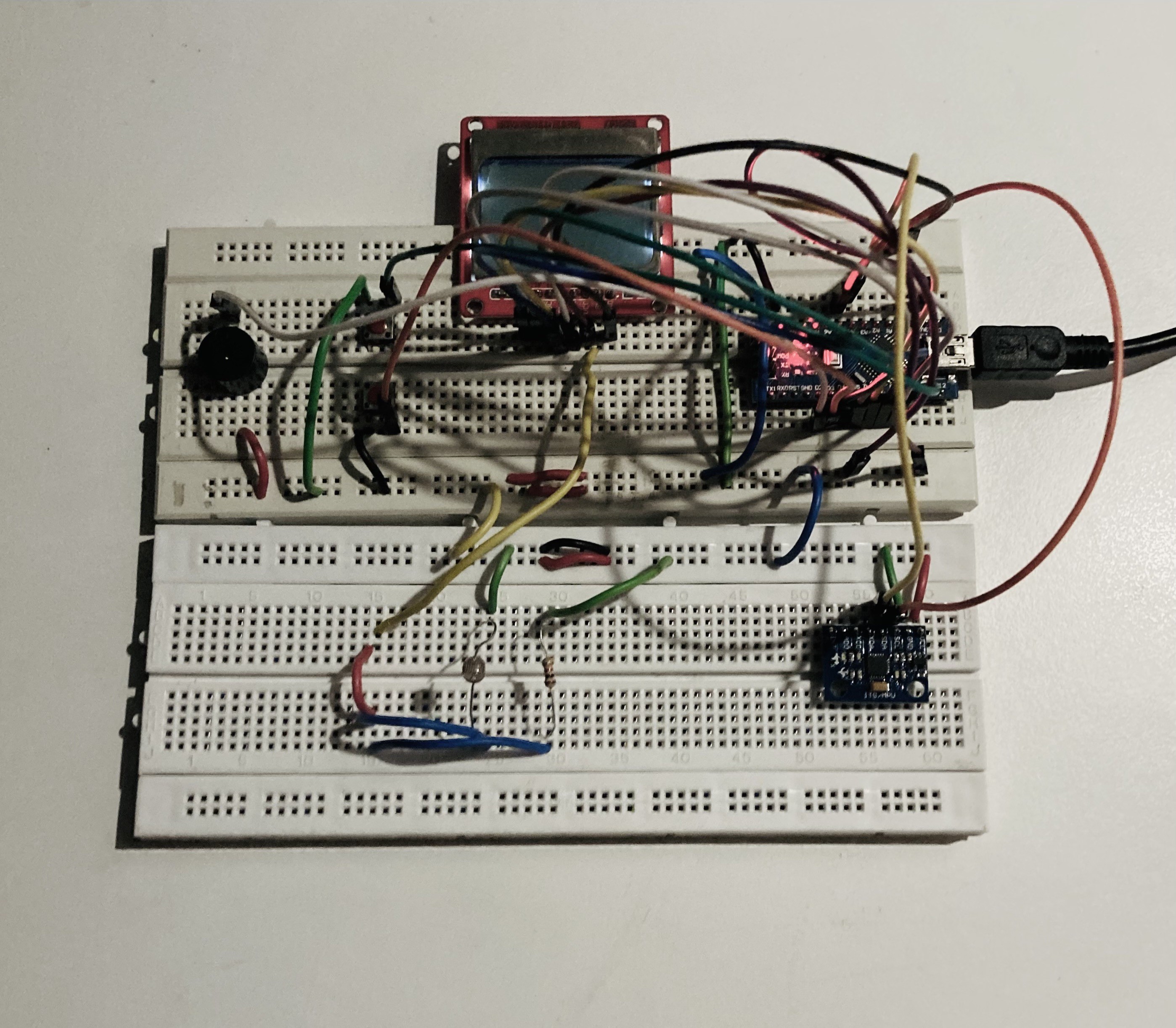
04/14/2022 at 17:00 • 0 commentsOne of the main components I have used in this project is the MPU6050 gyro sensor. The gyro sensor has brought in a physical aspect to my game which now requires the player to rotate the console sideways in order to move their character horizontally. The player can control the vertical movement using 2 buttons.

The gyro sensor has 8 GPIO pins but I have only connected 4 to the arduino nano for this project. The ones I have used are :
VCC and GND Pins - To provide power to the gyro sensor (gyro sensor requires 3.3V)
SCL and SDA Pins - For communication
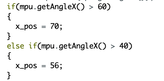
One of the challenges I faced was figuring out how to measure the angle of rotation using the gyro sensor. Eventually I understood how to measure the angle of rotation and then programmed my game to change the player's x position based on the angle measure by the gyro sensor along the x axis. I have used the MPU6050_light library to measure the angle along the x axis.
Changing the player's position based on the measurements from the gyro sensor -
Automatic Light Circuit
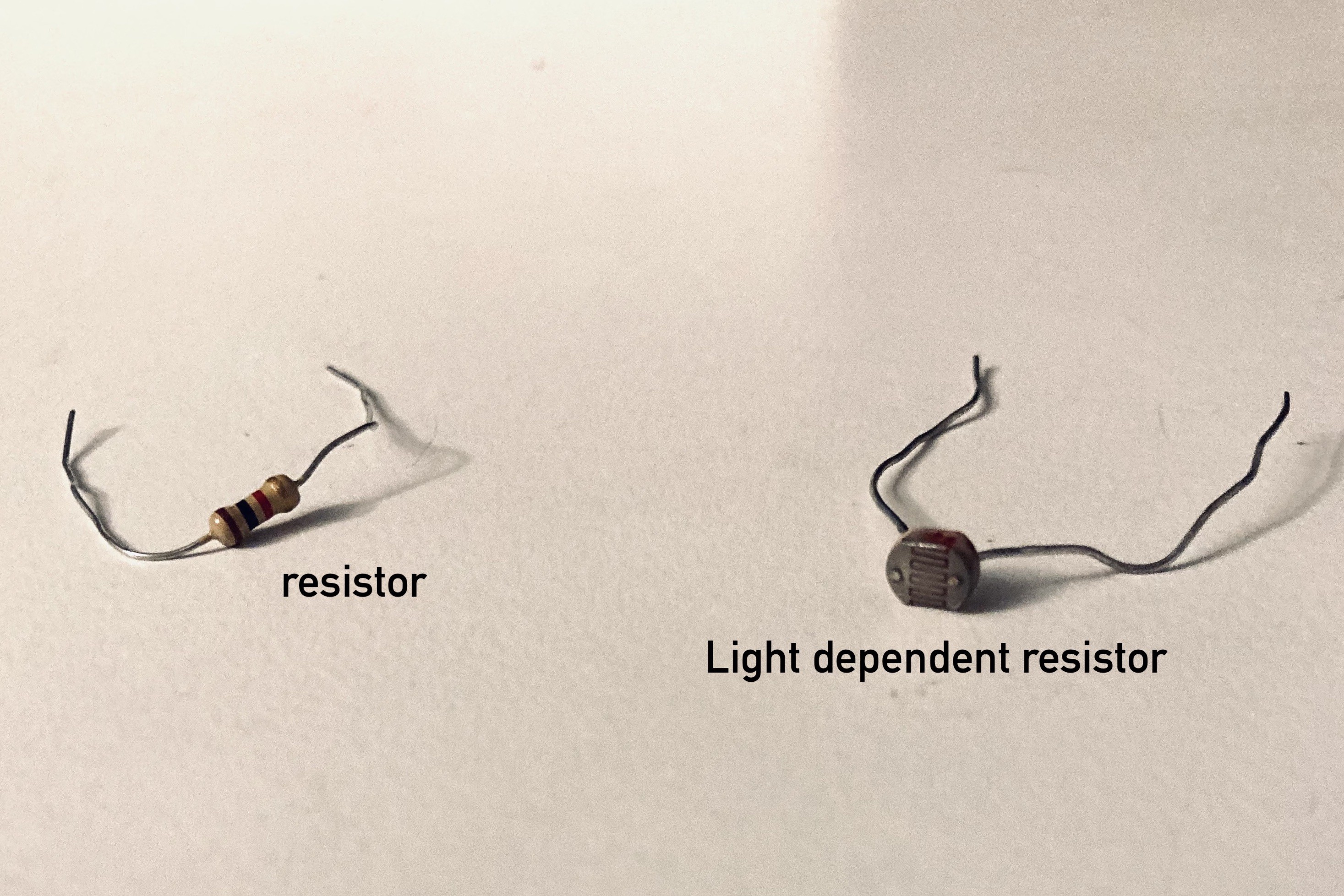
03/21/2022 at 16:55 • 0 commentsI have built a circuit to automatically control the backlights of the Nokia 5110 screen. I had specifically chosen the Nokia 5110 screen because of its unique backlights. The circuit which I have built would control the intensity of the backlights based on the surrounding light intensity. When the surrounding light intensity increases the intensity of the backlights would decrease and vice versa. To build this I have used a light dependent resistor, a normal resistor of small resistance ( for instance of 1K ohms) and some wires.
When surrounding light falls on the LDR (light dependent resistor) the resistance of the LDR reduces. Directly connecting the LDR to the backlight pin on the Nokia 5110 will cause the backlights to turn on when there is higher surrounding light intensity. However, I wanted the opposite to happen. So, I built a circuit to reverse the process.
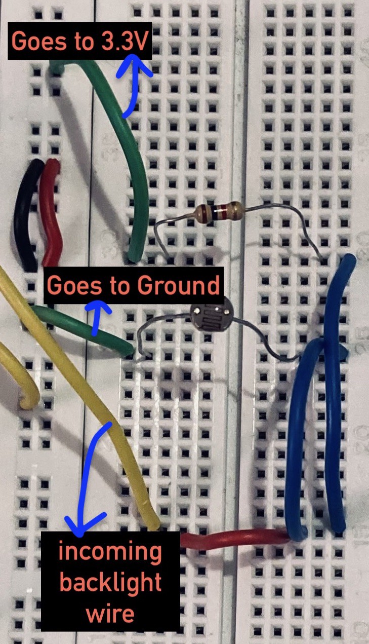
This is a parallel circuit in which the current can flow through 2 paths. Current always flows through the path of least resistance. Here one path has the LDR while the other path has a normal resistor (of low resistance). When it is dark (surrounding light intensity is low), the resistance of the LDR will be very high and hence the current will flow through the other path which means it will flow through the normal resistor. This path is connected to the 3.3V power supply. So, in the dark the Nokia 5110 backlights will receive power and hence turn on. However, when it is bright (surrounding light intensity is high), the LDR will have a very low resistance and hence current will flow through the LDR . The LDR is connected to ground. So, in this case the Nokia 5110 backlights will not receive any power and hence will not turn on. Through this manner the intensity of the Nokia 5110 backlight is controlled by the surrounding light intensity.
Backlights do not turn on when it is bright. Backlights turn on when it is dark.