deʃhipu
-
Multiple I²C Addresses
11/08/2017 at 10:54 • 0 commentsAs mentioned by @Matrix User in the comments, the new firmware doesn't support selecting of the I²C address with the jumper pads on the bottom of the board — instead the address is fixed in the firmware. There is an issue reported about this at https://github.com/pbugalski/wemos_motor_shield/issues/3 and some workarounds, including alternate builds of the firmware with different hard-coded addresses.
-
Reprogramming Without Soldering
04/21/2017 at 18:10 • 8 commentsTurns out that the procedure in the previous log can be greatly simplified. You don't need an ST-Link programmer, and you don't need to solder anything. Even if your shield is locked, you can unlock and program it with a simple serial adapter. Here is how.
First, clone the repository:
$ git clone https://github.com/pbugalski/wemos_motor_shield
$ cd wemos_motor_shield
Make sure you have arm-none-eabi-gcc installed, and compile it:
$ make
arm-none-eabi-gcc -Wall -g -std=c99 -Os -mlittle-endian -mcpu=cortex-m0 -march=armv6-m -mthumb -ffunction-sections -fdata-sections -Wl,--gc-sections -Wl,-Map=motor_shield.map -Iinc src/startup_stm32.s src/main.c src/user_i2c.c src/tb6612.c -o motor_shield.elf -Tstm32f030.ld
arm-none-eabi-objcopy -O binary motor_shield.elf motor_shield.bin
arm-none-eabi-size motor_shield.elf
   text	   data	    bss	    dec	    hex	filename
   2032	   1084	   1056	   4172	   104c	motor_shield.elf
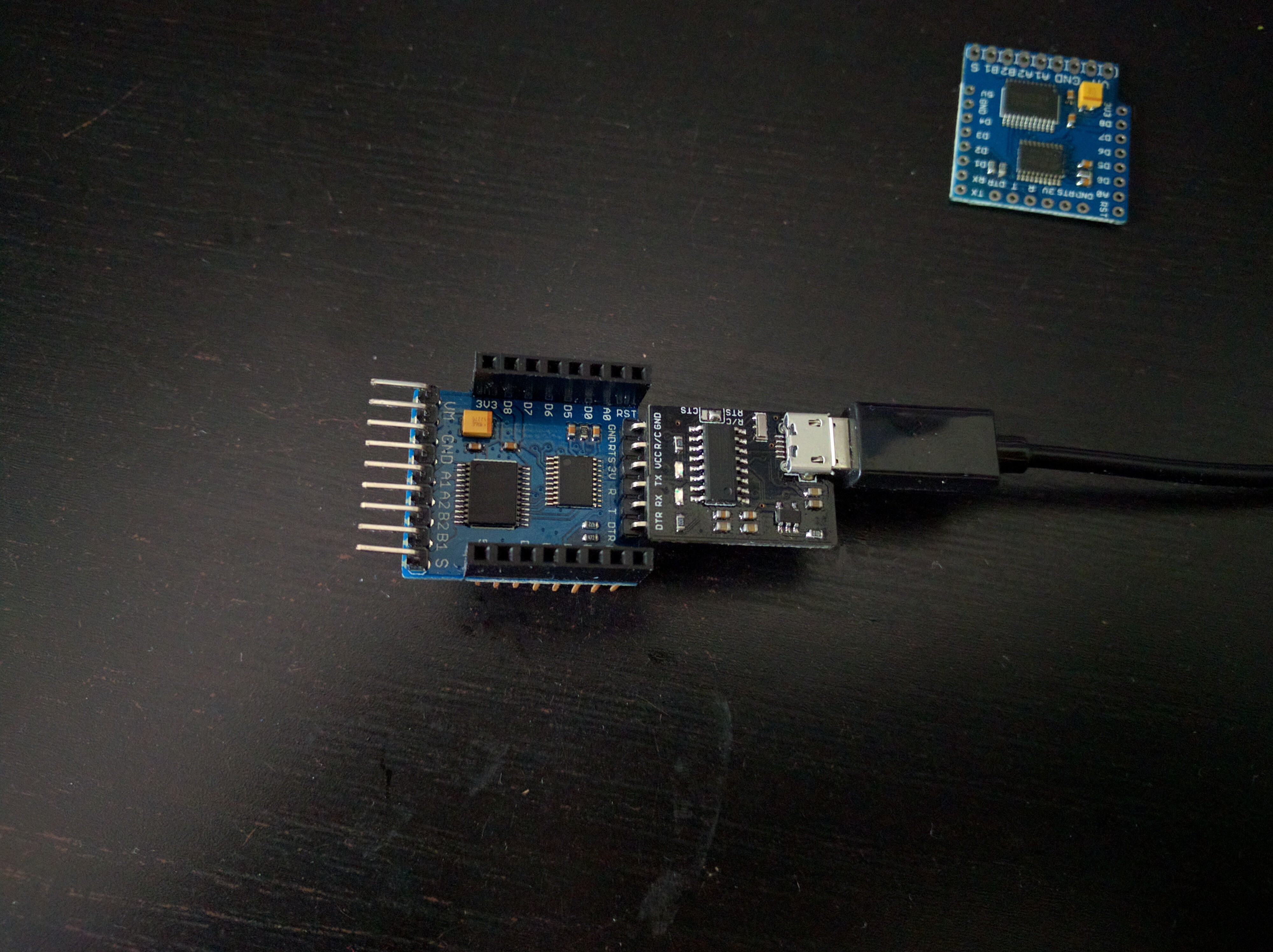
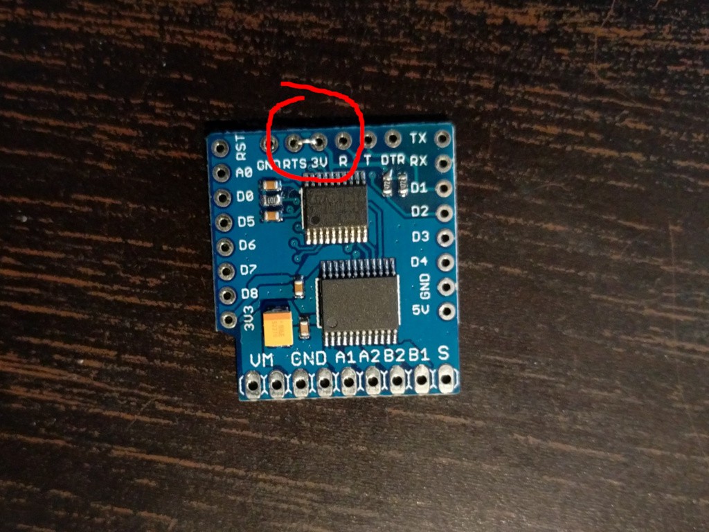
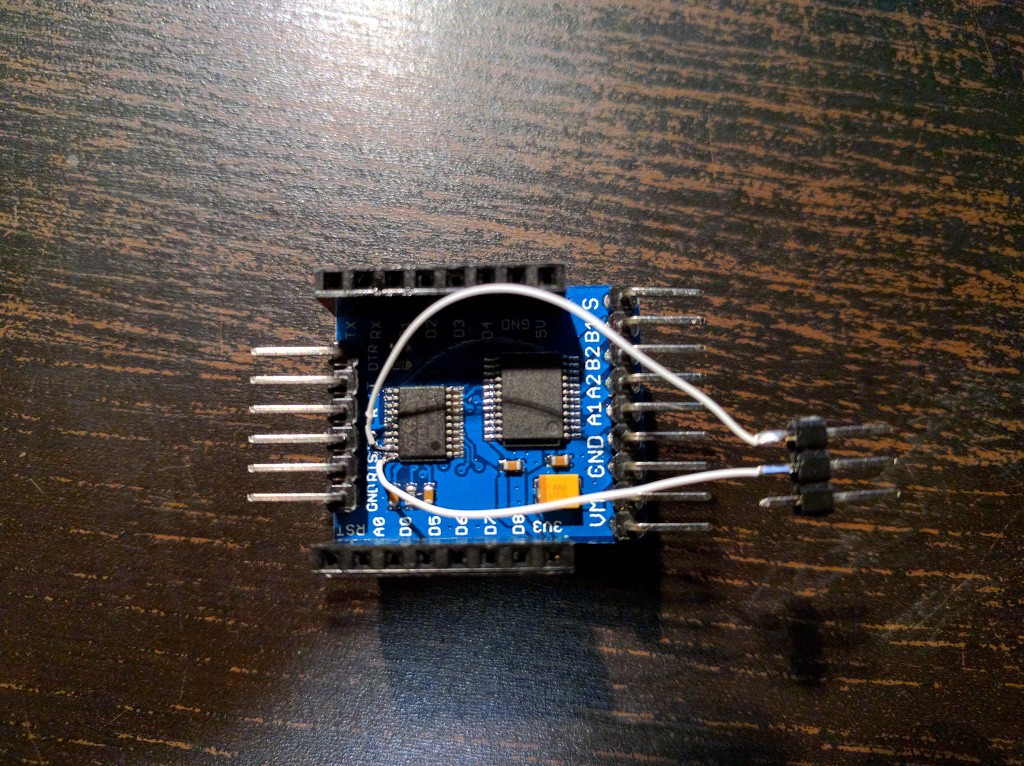
Now, make sure you have stm32flash utility installed. Short the RTS and the 3V pins on the shield together, like this:
And the connect the main pins of the shield to your USB2TTL as follows:![]()
GND ↔ GND
3V3 ↔ 3V3 (or VCC or whatever it is called on your USB2TTL)
D2 ↔ TX
D1 ↔ RX
and connect it to your computer. Now, see if you can communicate with the device:
$ stm32flash /dev/ttyUSB0
stm32flash 0.5

http://stm32flash.sourceforge.net/

Interface serial_posix: 57600 8E1
Version      : 0x31
Option 1     : 0x00
Option 2     : 0x00
Device ID    : 0x0444 (STM32F03xx4/6)
- RAM        : 4KiB  (2048b reserved by bootloader)
- Flash      : 32KiB (size first sector: 4x1024)
- Option RAM : 16b
- System RAM : 3KiB
Now, you can unlock your shield:
$ stm32flash /dev/ttyUSB0 -k
stm32flash 0.5

http://stm32flash.sourceforge.net/

Interface serial_posix: 57600 8E1
Version      : 0x31
Option 1     : 0x00
Option 2     : 0x00
Device ID    : 0x0444 (STM32F03xx4/6)
- RAM        : 4KiB  (2048b reserved by bootloader)
- Flash      : 32KiB (size first sector: 4x1024)
- Option RAM : 16b
- System RAM : 3KiB
Read-UnProtecting flash
Done.

$ stm32flash /dev/ttyUSB0 -u
stm32flash 0.5

http://stm32flash.sourceforge.net/

Interface serial_posix: 57600 8E1
Version      : 0x31
Option 1     : 0x00
Option 2     : 0x00
Device ID    : 0x0444 (STM32F03xx4/6)
- RAM        : 4KiB  (2048b reserved by bootloader)
- Flash      : 32KiB (size first sector: 4x1024)
- Option RAM : 16b
- System RAM : 3KiB
Write-unprotecting flash
Done.
And now you can flash it:$ stm32flash /dev/ttyUSB0 -v -w motor_shield.bin stm32flash 0.5 http://stm32flash.sourceforge.net/ Using Parser : Raw BINARY Interface serial_posix: 57600 8E1 Version : 0x31 Option 1 : 0x00 Option 2 : 0x00 Device ID : 0x0444 (STM32F03xx4/6) - RAM : 4KiB (2048b reserved by bootloader) - Flash : 32KiB (size first sector: 4x1024) - Option RAM : 16b - System RAM : 3KiB Write to memory Erasing memory Wrote and verified address 0x08000c2c (100.00%) Done.
Then disconnect all the wires (including the RTS pin), connect the shield to your WeMos D1 Mini, and it should work.
-
We Have a Fixed Firmware!
04/21/2017 at 17:21 • 5 comments@Piotr Bugalski has recently re-written the firmware for this motor shield, and published it at https://github.com/pbugalski/wemos_motor_shield. From what I can tell, the new firmware is compatible with the old one, minus the hanging and crashing, so it should be perfect for a drop-in replacement.
Here is how you can flash it to your shield:
Solder two wires to the first two legs of the microcontroller, counting from the top, like this:
![]() Be careful to not short them with the legs next to them. This is probably the hardest part.
Be careful to not short them with the legs next to them. This is probably the hardest part.Next, connect you ST-Link programmer as follows:
SWCLK ↔ first wire
SWDIO ↔ second wire
GND ↔ GND
3V3 ↔ 3V3
T_JRST ↔ RST
Note that, this is with the shiled *not* connected to the D1 Mini.
Now, clone the repository:
$ git clone https://github.com/pbugalski/wemos_motor_shield
$ cd wemos_motor_shield
Make sure you have installed openocd and arm-none-eabi-gcc. Compile the firmware:
$ make
arm-none-eabi-gcc -Wall -g -std=c99 -Os -mlittle-endian -mcpu=cortex-m0 -march=armv6-m -mthumb -ffunction-sections -fdata-sections -Wl,--gc-sections -Wl,-Map=motor_shield.map -Iinc src/startup_stm32.s src/main.c src/user_i2c.c src/tb6612.c -o motor_shield.elf -Tstm32f030.ld
arm-none-eabi-objcopy -O binary motor_shield.elf motor_shield.bin
arm-none-eabi-size motor_shield.elf
   text	   data	    bss	    dec	    hex	filename
   2032	   1084	   1056	   4172	   104c	motor_shield.elf
And flash it onto the shield:
$ make program
openocd -f stm32f0motor.cfg -f stm32f0-openocd.cfg -c "stm_flash motor_shield.bin" -c shutdown
Open On-Chip Debugger 0.9.0 (2015-09-02-10:42)
Licensed under GNU GPL v2
For bug reports, read
	http://openocd.org/doc/doxygen/bugs.html
Info : The selected transport took over low-level target control. The results might differ compared to plain JTAG/SWD
adapter speed: 1000 kHz
adapter_nsrst_delay: 100
none separate
srst_only separate srst_nogate srst_open_drain connect_deassert_srst
Info : Unable to match requested speed 1000 kHz, using 950 kHz
Info : Unable to match requested speed 1000 kHz, using 950 kHz
Info : clock speed 950 kHz
Info : STLINK v2 JTAG v17 API v2 SWIM v4 VID 0x0483 PID 0x3748
Info : using stlink api v2
Info : Target voltage: 3.490340
Info : stm32f0x.cpu: hardware has 4 breakpoints, 2 watchpoints
stm_erase
target state: halted
target halted due to debug-request, current mode: Thread
xPSR: 0xc1000000 pc: 0xfffffffe msp: 0xfffffffc
auto erase enabled
Info : device id = 0x10006444
Info : flash size = 16kbytes
target state: halted
target halted due to breakpoint, current mode: Thread
xPSR: 0x61000000 pc: 0x2000003a msp: 0xfffffffc
wrote 4096 bytes from file motor_shield.bin in 0.287988s (13.889 KiB/s)
target state: halted
target halted due to breakpoint, current mode: Thread
xPSR: 0x61000000 pc: 0x2000002e msp: 0xfffffffc
verified 3116 bytes in 0.057512s (52.910 KiB/s)
shutdown command invoked
Now, disconnect everything. Your board has the new firmware on it. You can test it, and then desolder the two wires -- you won't be needing them anymore. -
SWD Programming Continued
11/22/2016 at 20:59 • 1 commentOn a quest to configure OpenOCD properly. First of all, the error I'm getting was described in an issue and seems like adding "reset_config none separate" fixes that. I got a new error with this:
openocd -f extra/fff.cfg -f extra/stm32f0-openocd.cfg -c "stm_flash `pwd`/main.bin" -c shutdown
Open On-Chip Debugger 0.9.0 (2015-09-02-10:42)
Licensed under GNU GPL v2
For bug reports, read
	http://openocd.org/doc/doxygen/bugs.html
Info : The selected transport took over low-level target control. The results might differ compared to plain JTAG/SWD
adapter speed: 1000 kHz
adapter_nsrst_delay: 100
none separate
srst_only separate srst_nogate srst_open_drain connect_deassert_srst
Info : Unable to match requested speed 1000 kHz, using 950 kHz
Info : Unable to match requested speed 1000 kHz, using 950 kHz
Info : clock speed 950 kHz
Info : STLINK v2 JTAG v17 API v2 SWIM v4 VID 0x0483 PID 0x3748
Info : using stlink api v2
Info : Target voltage: 3.504912
Info : stm32f0x.cpu: hardware has 4 breakpoints, 2 watchpoints
none separate
stm_erase
target state: halted
target halted due to debug-request, current mode: Handler HardFault
xPSR: 0xc1000003 pc: 0xfffffffe msp: 0xfffffffc
auto erase enabled
Info : device id = 0x10006444
Info : flash size = 16kbytes
Error: stm32x device protected
Error: failed erasing sectors 0 to 0
OK, so apparently the chip is write-protected. No problem, we can unlock it with "stm32x unlock 0". After running that, and resetting the chip, I finally got:openocd -f extra/fff.cfg -f extra/stm32f0-openocd.cfg -c "stm_flash `pwd`/main.bin" -c shutdown Open On-Chip Debugger 0.9.0 (2015-09-02-10:42) Licensed under GNU GPL v2 For bug reports, read http://openocd.org/doc/doxygen/bugs.html Info : The selected transport took over low-level target control. The results might differ compared to plain JTAG/SWD adapter speed: 1000 kHz adapter_nsrst_delay: 100 none separate srst_only separate srst_nogate srst_open_drain connect_deassert_srst Info : Unable to match requested speed 1000 kHz, using 950 kHz Info : Unable to match requested speed 1000 kHz, using 950 kHz Info : clock speed 950 kHz Info : STLINK v2 JTAG v17 API v2 SWIM v4 VID 0x0483 PID 0x3748 Info : using stlink api v2 Info : Target voltage: 3.506483 Info : stm32f0x.cpu: hardware has 4 breakpoints, 2 watchpoints none separate stm_erase target state: halted target halted due to debug-request, current mode: Thread xPSR: 0xc1000000 pc: 0xfffffffe msp: 0xfffffffc auto erase enabled Info : device id = 0x10006444 Info : flash size = 16kbytes target state: halted target halted due to breakpoint, current mode: Thread xPSR: 0x61000000 pc: 0x2000003a msp: 0xfffffffc wrote 1024 bytes from file /home/sheep/dev/3rdparty/stm32f0-discovery-basic-template/main.bin in 0.104813s (9.541 KiB/s) target state: halted target halted due to breakpoint, current mode: Thread xPSR: 0x61000000 pc: 0x2000002e msp: 0xfffffffc verified 980 bytes in 0.030723s (31.150 KiB/s) shutdown command invoked
Which seems to be a correct flashing.
All this thanks to advice from @jaromir.sukuba, great thanks!
Now let's see if I can get a blink example to work...
-
SWD Programming
11/22/2016 at 20:06 • 0 commentsSecond approach to this is using the SWD protocol with my Chinese ST-Link V2 clone. That requires getting at the SWD pins. Fortunately, they are near the edge of the chip:
![]()
Then I connected it according to the pinout of my programmer (the second one):
![]()
Now just "make program" in that template, and...
openocd -f /usr/share/openocd/scripts/board/stm32f0discovery.cfg -f extra/stm32f0-openocd.cfg -c "stm_flash `pwd`/main.bin" -c shutdown
Open On-Chip Debugger 0.9.0 (2015-09-02-10:42)
Licensed under GNU GPL v2
For bug reports, read
	http://openocd.org/doc/doxygen/bugs.html
Info : The selected transport took over low-level target control. The results might differ compared to plain JTAG/SWD
adapter speed: 1000 kHz
adapter_nsrst_delay: 100
none separate
srst_only separate srst_nogate srst_open_drain connect_deassert_srst
Info : Unable to match requested speed 1000 kHz, using 950 kHz
Info : Unable to match requested speed 1000 kHz, using 950 kHz
Info : clock speed 950 kHz
Info : STLINK v2 JTAG v17 API v2 SWIM v4 VID 0x0483 PID 0x3748
Info : using stlink api v2
Info : Target voltage: 3.497322
Info : stm32f0x.cpu: hardware has 4 breakpoints, 2 watchpoints
stm_erase
Error: timed out while waiting for target halted
TARGET: stm32f0x.cpu - Not halted
in procedure 'stm_flash'
in procedure 'reset' called at file "extra/stm32f0-openocd.cfg", line 8
in procedure 'ocd_bouncer'


Makefile:72: recipe for target 'program' failed
make: *** [program] Error 1
Failure.
I suspect that I shouldn't be using the configuration for the discovery board, but somehow write my own, however, I can't seem to be able to find any examples...
-
Serial Programming
11/21/2016 at 10:12 • 1 commentLast evening I made the first try at programming this thing. From the datasheet and the schematic it looks straightforward: the BOOT0 pin is connected to the RTC pin of the serial, the NRST pin is connected to DTR, it should just work. So I connected the USB2TTL (also a WeMos one), and gave it a go:
![]()
$ stm32flash /dev/ttyUSB0
stm32flash 0.5

http://stm32flash.sourceforge.net/

Interface serial_posix: 57600 8E1
Failed to init device.
No joy. To the datasheet then! Hmm, they mention a BOOT1 there too, but it's nowhere to be seen as a pin... Let's google for it... http://stackoverflow.com/questions/22351703/stm32f030-and-boot0-pin Ah-ha! It looks like BOOT1 is a flag in something called "user flash option byte", and it has to be set to 0 for the bootloader to start. Shame I have no way to check it.
If that flag is set to 1 in this firmware, then the only way to reprogram this board is to use an stlink programmer. Fortunately, I do have one! Unfortunately, the SWD and SWC pins are not broken out, so I guess I will need to do some precision soldering directly to the chip's legs. Oh well.
Motor Shield Reprogramming
Create and flash new firmware for the WeMos D1 Mini Motor Shield.
 Be careful to not short them with the legs next to them. This is probably the hardest part.