 Timo
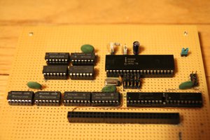
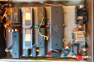
TimoWhen i was rummaging around in my fathers basement i found a box of old diy kits. PCBs and ICs all in original packaging plus some already put together ones. A quick look at the chips revealed a 6502, RAM, glue logic and two I/O expander but no ROM. So this is probably a basic 6502 computer.
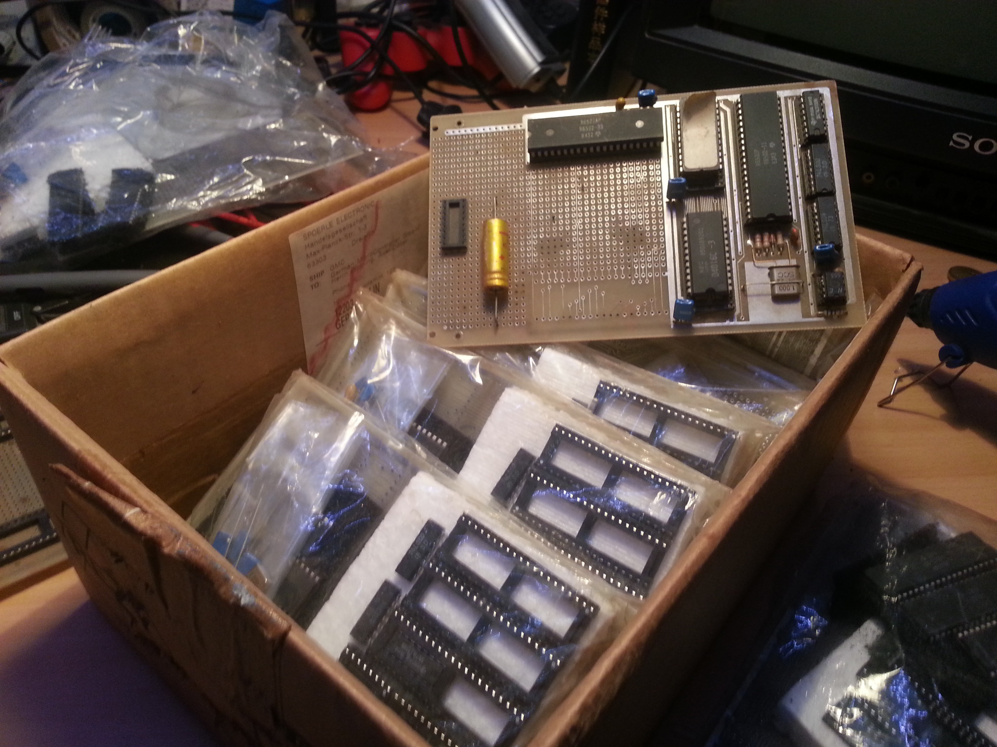
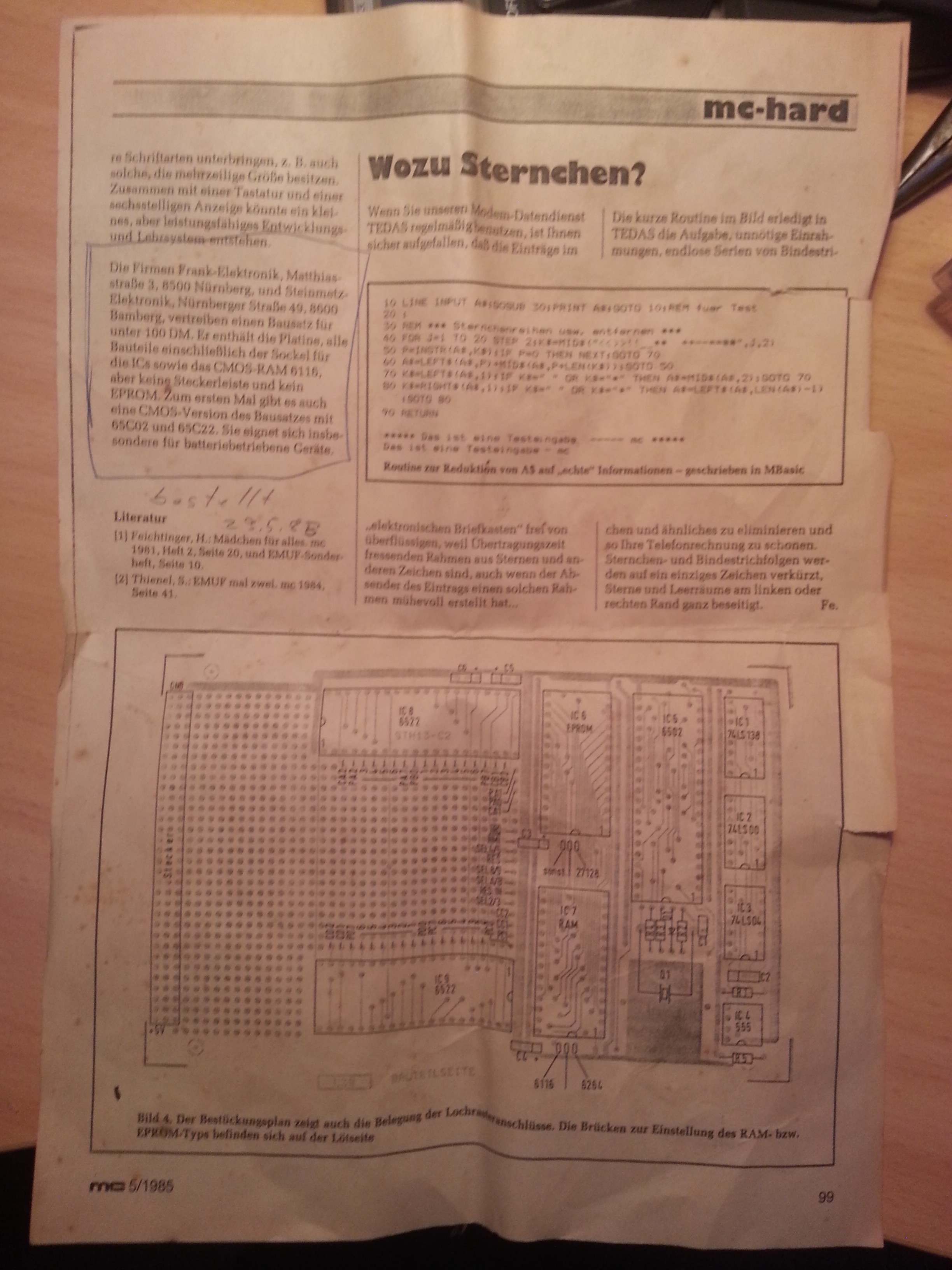
I also found (parts of) an old article from a magazine which basically saies that there is a super cheap (only 100 German Mark) diy computer that you can buy now. Someone scribeled the ordering date on it. Presumably they were ordered at 29.06.1985. So these kits are five years older than me.
Unfortunatly i know nothing about the 6502 exept that it was a thing. Also i did not found any aditional information about the kit or schematic. So i thought that i would be a perfect oportunity to learn something about the 6502 by reverse engeneering this old diy computer kit. You can see what i got here:
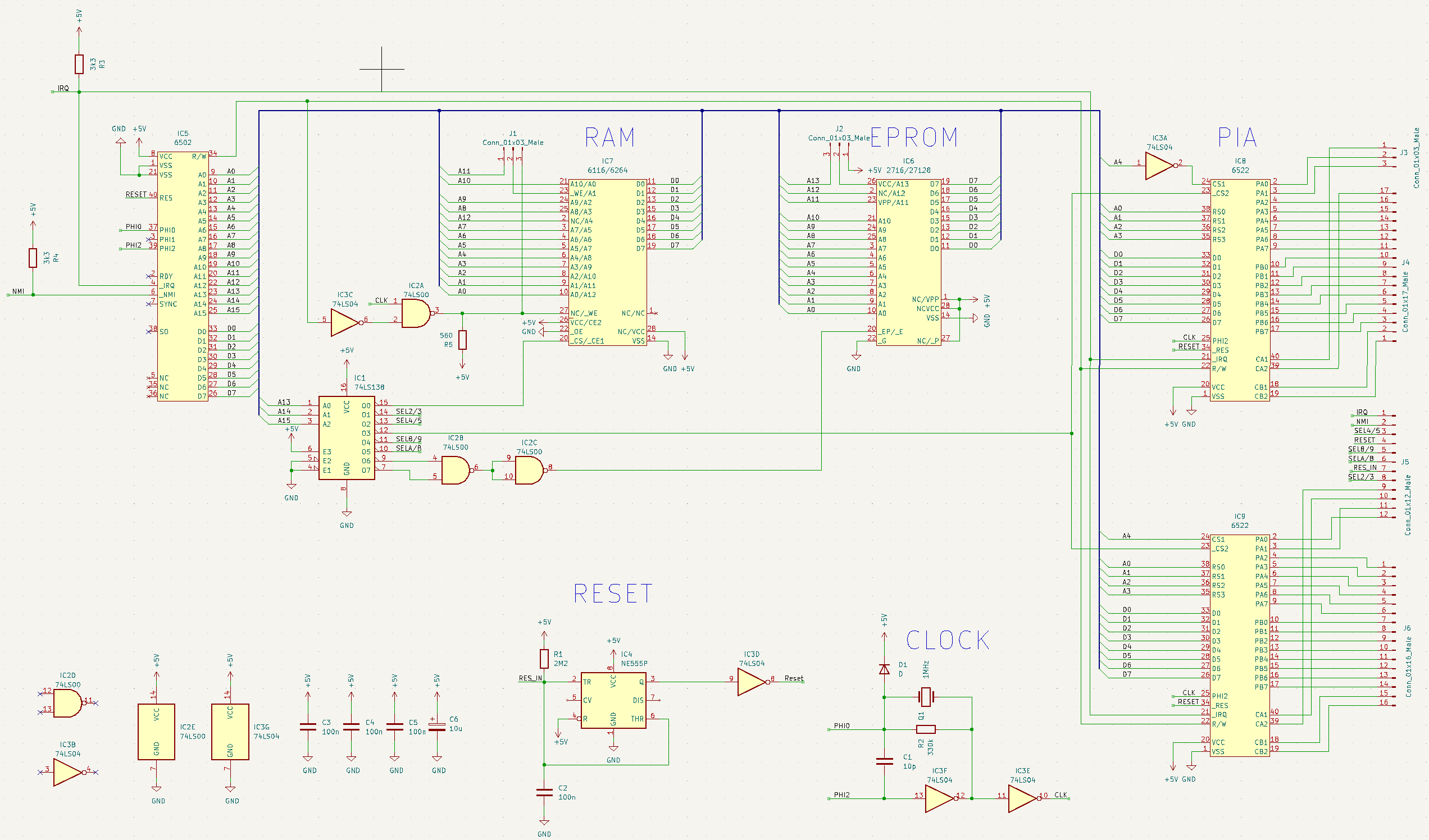
The board has two options for RAM and ROM. You can choose between 2KB or 16kB of ROM and 2kB or 8kB of RAM. Depending on what you want you have to set the solder bridges J1 and J2. Onther than that there are only two PIAs who provide GPIOs. So this is more like a microcontroller and not like the retro gaming maschine i hoped for ^^. However, big parts of the adress space are not used and there is a lot of free proto raster on the board.
Bye the way: this schematic is not tested, so there is no guarantee that it is flawless. Especially the clock looks strange to me. I know it is probably a Pierce Oscillator, but shouldn't be C1 just a short? I checked three times but any explanation or hint is appreciated.
From the schematic i found this memory map. Again no guarantee.
| Chip | Start Address | Stop Address |
|---|---|---|
| RAM (6116) | 0x0000 | 0x07FF |
| RAM (6264) | 0x0000 | 0x1FFF |
| ROM (2716) | 0xC000 | 0xC7FF |
| ROM (27128) | 0xC000 | 0xFFFF |
| PIA (IC8) | 0x6000 | 0x600F |
| PIA (IC9) | 0x6010 | 0x601F |
The next step might be to get a toolchain running, learn 6502 ASM and then bring this thing to do something usefull.


 Bentendo64
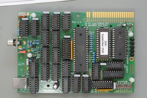
 Keith
Keith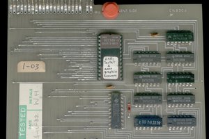
Hi, thanks for the reply. Actually the additonal resistors are Pull-up resistors for IRQ and a pin called NMI (i suppose that means Non-Mascable-Interrupt). I checked that again and could confirm this. The annotation from the schematic matches the magazine drawing. Although i realize now its blury. I will add a better scan. Thanks for your input.