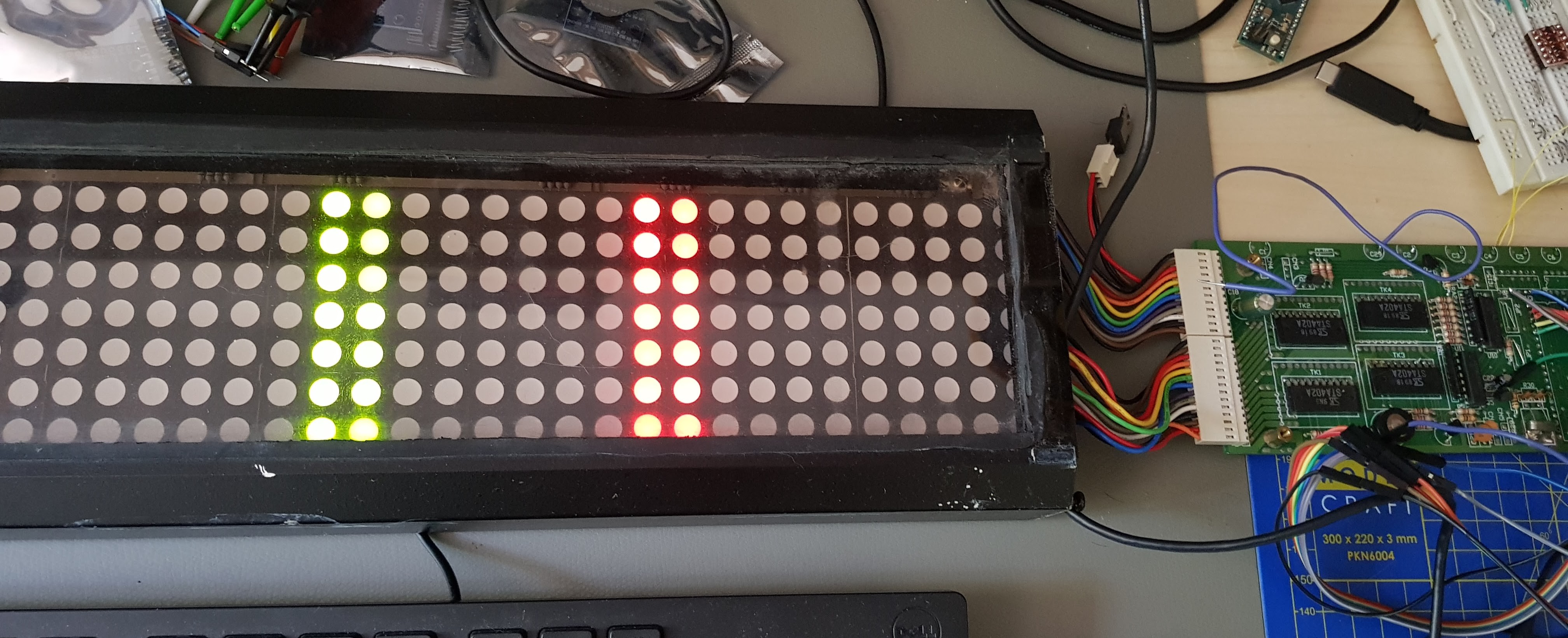
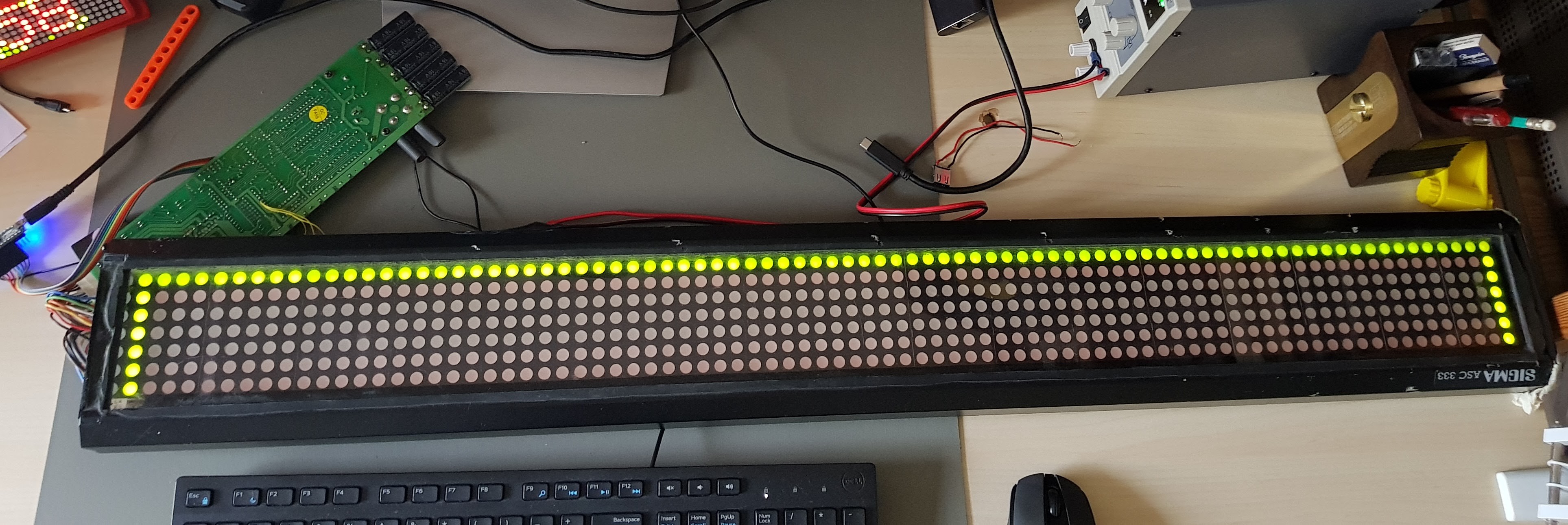
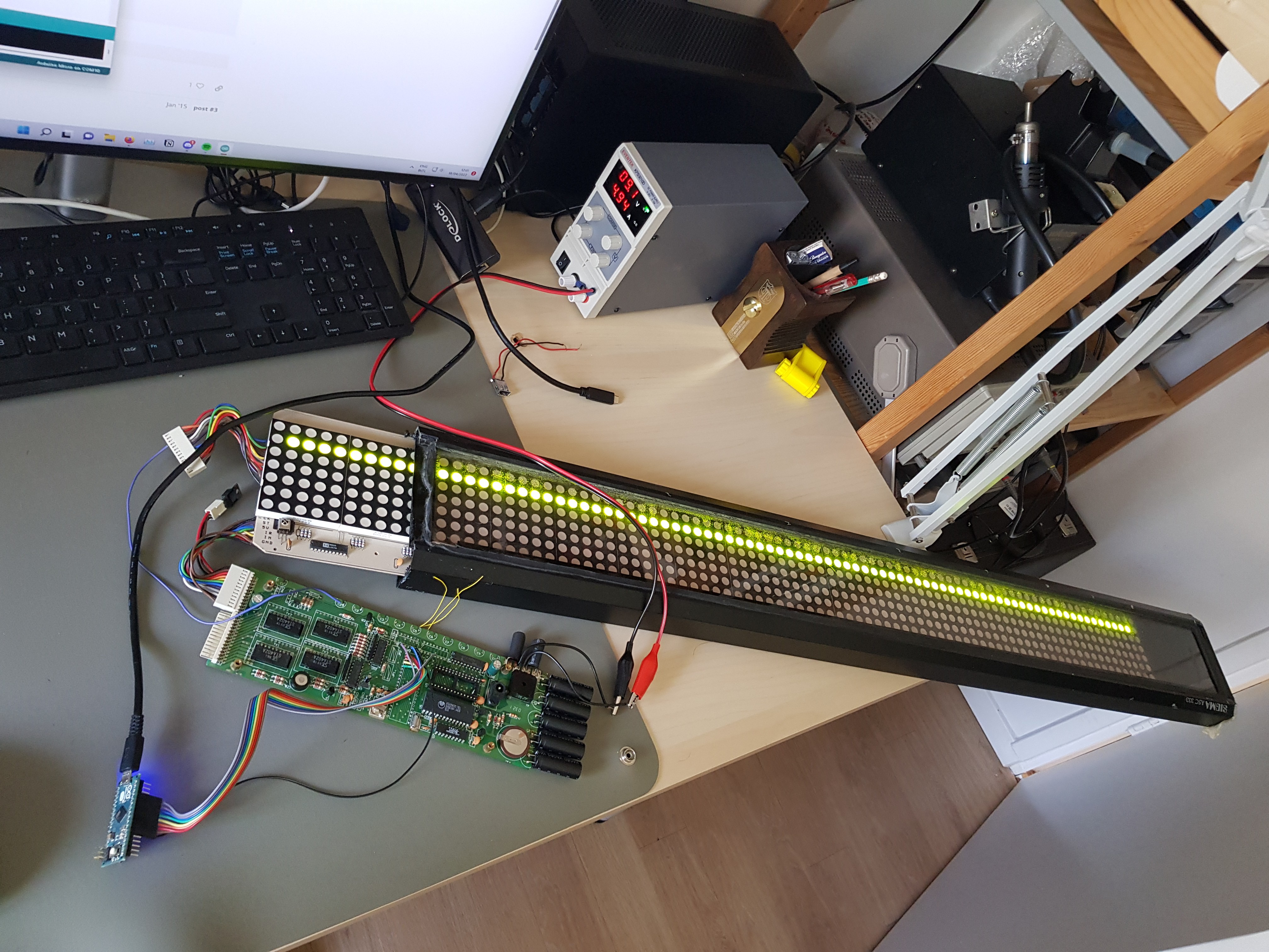
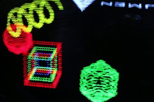
An adventure in '80s electronics and embedded Linux
To make the experience fit your profile, pick a username and tell us what interests you.
We found and based on your interests.
Schematic (reverse engineered).pdfThe reverse-engineered schematic of the controller board. Might have errors.Adobe Portable Document Format - 196.91 kB - 04/05/2022 at 19:40 |
|
|
The firmware development on the "video card" is going along nicely. I took an example project for the FRDM-KL25Z that was sending SPI data with FreeRTOS. Then I modified it to control the LED drivers via SPI.
You can have a look at the source code here: https://github.com/egueli/ASC333_Controller_MKL25Z4
I created a different task that runs a test animation. The two tasks communicate via a FreeRTOS queue: the queue contains image data (154 bytes to represent a full bicolor bitmap), and is just one item big.
The LED driver task is a loop, that retrieves an item from the queue and copies it into its buffer. If the queue is empty, no copy happens and it just reuses what was previously in the buffer. It then proceeds to display what's in the buffer, row by row, alternating red and green LEDs. It does so by sending the 11 bytes containing enough data to fill all the shift registers (74HC595-like) via SPI, in a format that the '595s are happy with. The task then waits 1ms between each scan (that's what the original circuity was doing). It takes 14ms to do a full scan, leading to slightly more than 60fps.
The task code also has a function that other tasks can use to submit new images. This function simply overwrites whatever is currently in the queue ("drop-oldest"), so the new image will be displayed as soon as the previous one has finished scanning.
The animation task creates an image buffer, fills it with a simple animating pattern of red and green lines, and submits it with the aforementioned function. Then it waits a couple hundred milliseconds before making a new frame. This task will soon be replaced by one that takes image data from SPI configured as slave, controlled by the Linux machine.
I decided I won't let the Linux machine control the display directly, not yet. For a few reasons:
HZ=1000
). This will make everything a bit harder to set up.Therefore, I'll let a separate MCU do the LED handling for now. I'll use an FRDM-KL25Z development board by Freescale:
I decided to use that instead of a traditional Arduino because I want to learn more about the ARM Cortex architecture, FreeRTOS, and other tools in "professional" embedded development.
The plan is to use this MCU as a "video card" that will directly control the row and column drivers. It will use one of its SPI peripherals as a master to control the column drivers, and the other as a SPI slave to get bitmap data from Linux. I'll then write a kernel driver that sends the right data to the MCU; maybe by also emulating a framebuffer device.
That's supposed to be a rectangle. But I made it 8 pixel tall instead of 7. And this small detail bricked the Arduino Micro 😅
The reason is that in my Arduino sketch I defined a framebuffer made of 7 byte arrays. Then I defined a couple graphics functions like `drawHorizontalLine` that would set the corresponding bits in the arrays. I didn't care for checking the boundaries, so when the sketch ran `drawHorizontalLine(y = 7)` it actually wrote somewhere outside the memory allocated for the framebuffer. That somewhere happened to be something related to the USB communication used by the Arduino Micro libraries, messing it up and making it incapable to talk with my PC. Repeated resets + upload lead to nothing. My only option left is reprogramming the MCU via the ICSP pins.
A couple notable things before reaching this point:
Next steps: reprogram the Arduino Micro before I put it back in the drawer, forget about it, pick it up months later, think it's broken and throw it away. Then, thinking that I'd like to try driving the LEDs straight from an embedded Linux machine:
Desoldering the three chips gave me access to the signals that control the LED matrix:
The numbers on the list above match the "resistor color codes" of the wires I soldered on the board:
At the other end of the wires, an Arduino Micro:
My objective for now is to be able to draw something with an Arduino at least. Since it's all 5V powered, that seems the easiest goal for now. I plan to reach that goal in three steps:
I've managed to do step 1, after finding a small mistake in the wiring (as the purple and gray wires are really similar in color in these wires). I can now control each of the LEDs of an individual row:
The thing draws 5A, that's 45W of power, same as specified in the power rating behind the case. That bridge rectifier is too hot to touch, but I think it can stand that.
Hacking the firmware seemed like a very complicated way to obtain a result, which could make this project very time-consuming, possibly grinding to a halt.
So I decided I wanted to give another go at the hard way, i.e. desoldering the three DIP chips that were controlling the LED driving circuitry and put my hardware in the middle.
Thanks to this Hackaday article and my hot air gun I successfully managed to desolder the MCU in its 40-pin DIP and two more logic chips.
Now it's just a matter of adding an Arduino to the right pins, to see if I can indeed control the row and column drivers.
If this is successful as well, I can replace the Arduino with a bunch of level shifters connected to the Linux embedded board.
My initial plan was to desolder the microcontroller (a Winbond W78C32C-40 MCU, with an 8051 core) plus a few other logic chips in the board, then add some wires to control the LED circuitry. But desoldering was tougher than I thought, and while in the process I though "wait, why don't I keep the MCU and reprogram its firmware to get pixel data from outside?"
Here's the idea: I dump the contents of the EPROM (a 27256 DIP which, by the way, is accessible and replaceable from outside the chassis) to my PC, reverse-engineer it, figure out how exactly are the LEDs controlled, then write an 8051 firmware of my own that somehow gets the data from the external Linux machine and displays it.
What to use to get the data? The marquee already has a serial connection (you'd use that on a PC to program the text, animations etc.) but the MCU datasheet puts a limit at 9600bps, too slow to get raw pixel data. I want the bi-color 85*7 display to be refreshed 60 times per second, so I need 2[bit per pixel]*85[columns]*7[rows]*60[fps] = 71400bps minimum.
So instead of using a serial connection, I might somehow add a "virtual memory" so that when the MCU reads it, it actually reads data coming from outside. Something like memory-mapped I/O.
The advantage of this approach is that you don't need to change anything in the existing hardware. No desoldering, no messing up with wires. Where the EPROM socket is, I would put a DIP IDC connector like this one that breaks out all its pins through a flat cable to another board, containing logic level shifters and anything else to interface the display to the Linux board.
The disadvantage is that it's another level of "hacking" this device; in addition to the hardware I need to have a deep understanding of how the firmware works. Sounds complicated, but also a really interesting challenge! What do you guys think?
Create an account to leave a comment. Already have an account? Log In.
Thanks! Indeed there's not much information online apart from a few pages. Will populate this page in the next few days.
Become a member to follow this project and never miss any updates
👍 I'm always interested in old displays, so looking forward to photos from you as there are few online. My search turned up this write-up in Dutch: https://revspace.nl/Lichtkrant_Sigma_ASC_333 which you have probably found too.