- Soldered all SMT components that weren't lost/destroyed/had a pad that ripped
- Ordered replacements for:
- C1
- C19
- C21,C22,C37,C39,C40,C41,C42
- C47,C48,C49,C52,C53,C57,C58
- C60,C61
- R21
- R56
- R58
- R59
- R60
- R66,R67,R70 R82so
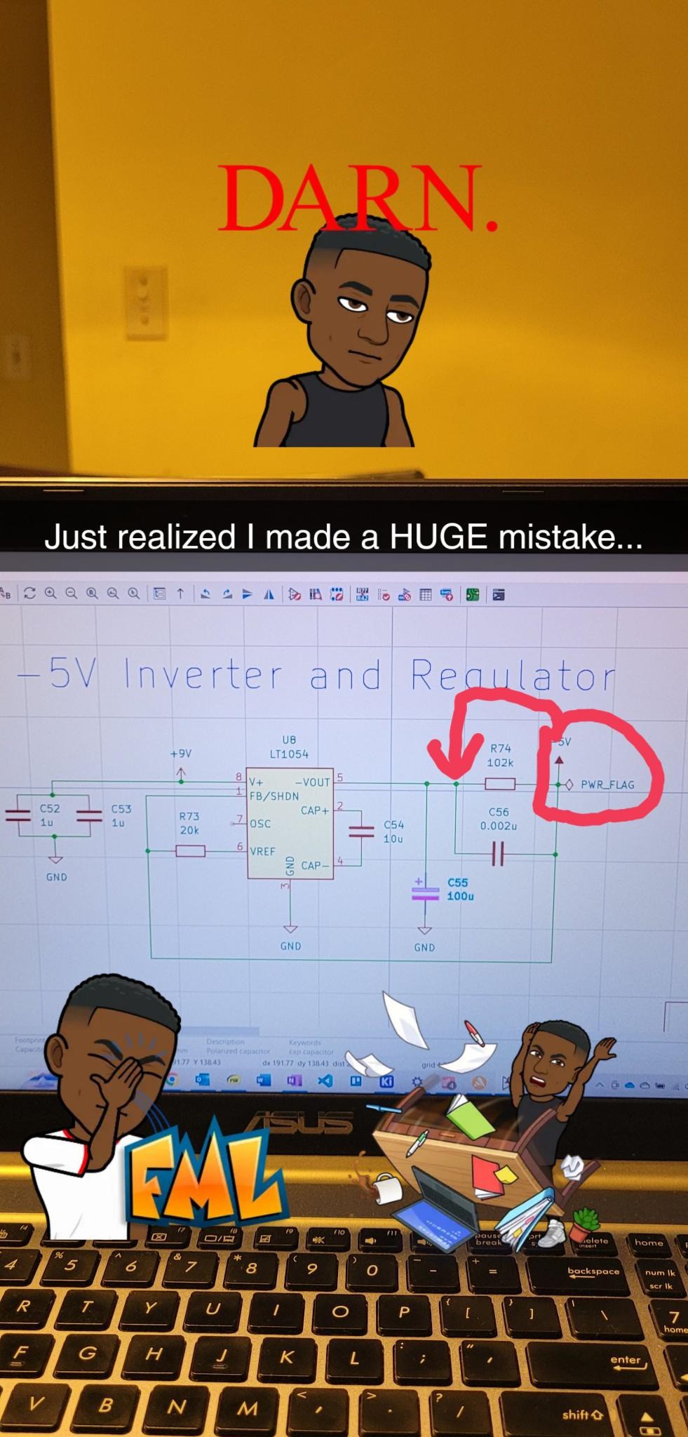
- While soldering -5V regulator and inverter I realized I made a mistake
![]()
- will cut and solder connect appropriate traces to remedy
- Soldered C1, R59, R66, R67, R70
Solder Progress 10
A project log for Music Spectrum and dB Visualizer
Receive input from a 3.5mm jack, divides the music into 7 frequency bands, shows the loudness of each frequency band in DB using LEDS.
 Ghani Lawal
Discussions
Become a Hackaday.io Member
Create an account to leave a comment. Already have an account? Log In.