-
Order Has Arrived
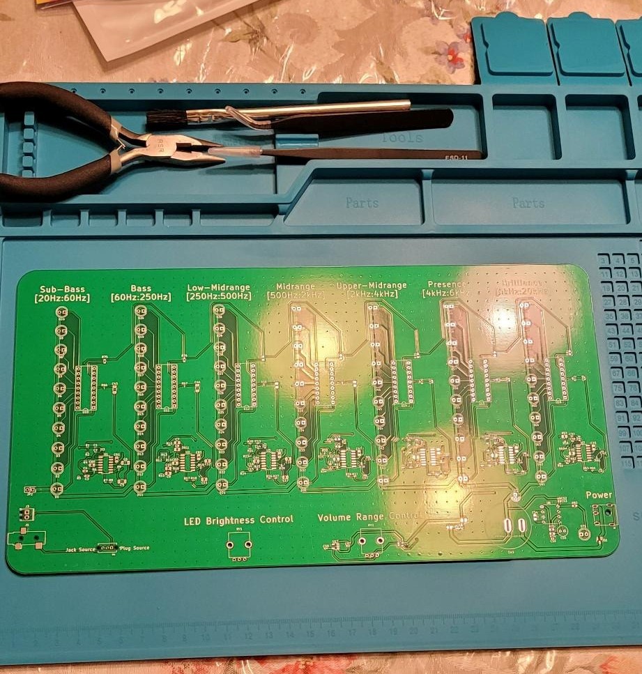
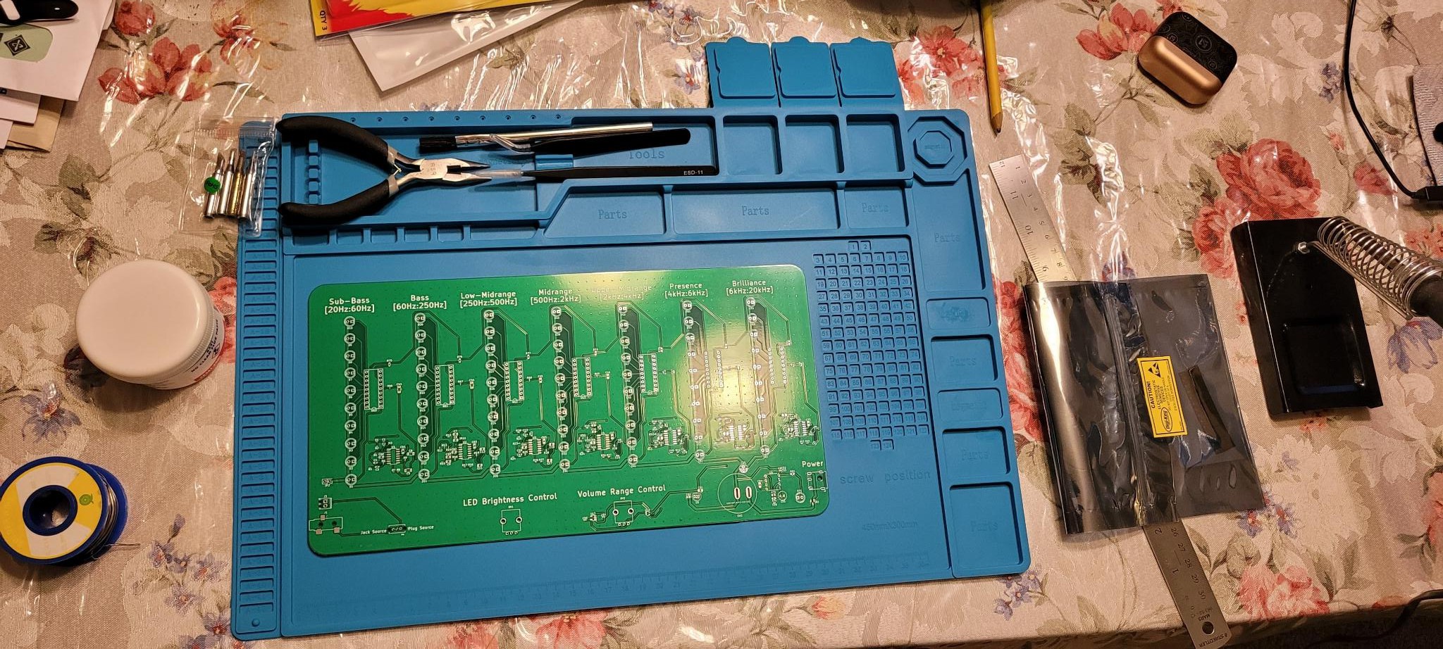
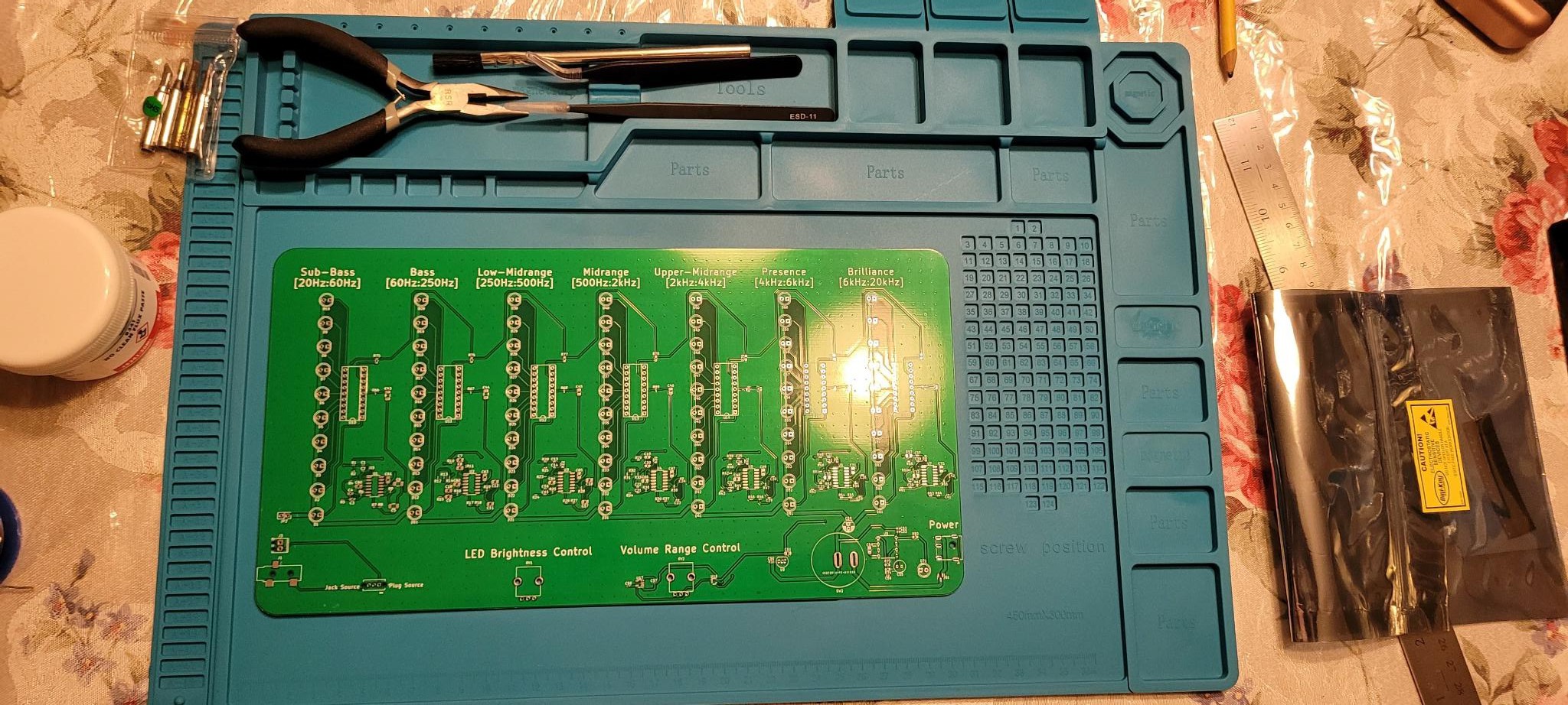
11/02/2022 at 00:00 • 0 comments- Yesterday all of the parts came in, electrical components from Digi-key and the PCB from JLCPCB
- Soldering tools such as flux paste and tweezers came in from amazon
- Currently watching videos on different ways to Solder
![]()
![]()
![]()
-
Component and PCB Order
10/26/2022 at 05:25 • 0 comments- Verified BOM, replaced components that are currently out of stock
- Order remaining components on Digi-Key
- Bought tools needed for SMT soldering on Amazon
- Ordered PCB on JLCPCB
-
Corrections and BOM
10/19/2022 at 07:27 • 0 comments- To save time, only made 'absolutely necessary corrections'
- Oriented R82 and D71 correctly in schematic
- Added 0.1uF decoupling capacitors for op amps
- Moved decoupling capacitors closer to IC it is supporting
- Moved ports closer to the edge
- Added reverse voltage protection at the power port
- Added stitching vias
- Started making BOM
- Sourcing everything from Digi-key
- Started sourcing components on Digi-key, down 15 out of 91
- Made a mistake in the footprint from some of the capacitors, some are non-stocked on Digi-Key and or Mouser, all of the issues were resolved
- To save time, only made 'absolutely necessary corrections'
-
Design Review
09/27/2022 at 04:56 • 0 commentsPosted schematic and PCB on Reddit for a design review - https://www.reddit.com/r/PrintedCircuitBoard/comments/xo5yta/design_review_audio_visualizer/
- Add stitching vias to the ground pour
- Use the thickest traces I can get away with
- Don't daisy chain the power connections, use star formation
- Be mindful of physical construction of the plugs
- Move capacitors closer to the IC it is supporting
- At 0.1uF Low ESR caps to power pins of op-amps
- R82 & D71 should point downward, not to the right. (in the schematic)
- J2 (DC power jack) should have reverse voltage protection
- Add high impedance input buffer to filter section to avoid unnecessary loading, such as a JFET op amp, could also just use extra op amp in each filter section as the buffer
- If I don't use the extra op amps, consider tying them together
-
Finished PCB!!
09/22/2022 at 22:18 • 0 comments- Finished Tracing +/-5V power
- Traced Brightness and volume range control
- Found "Phoenix Contact 1725656" Terminal Block to connect Male audio jack to
- Traced audio input and mode header
- All nets, subcircuits etc. have been routed, now will commence with design review, then doublecheck BOM, then order PCB!!!
-
Ground Pour
09/21/2022 at 01:54 • 0 comments- Applied copper ground fill to top and bottom layer
- Ground pads of IC's where filters were traced were not connected from the copper pour:
- created new topology to remove problem
- Successfully retraced Sub-bass and bass filters
-
PCB Update
09/08/2022 at 23:49 • 0 comments- Got 3D models for all components
- Formatted and aligned all the sub-circuits in the PCB editor
- Found a PCB design fundamentals resource http://alternatezone.com/electronics/files/PCBDesignTutorialRevA.pdf and posted (at the time) current PCB with LED driver and 2 filters traced on Reddit for a design review
- PCB making is subtractive process, better to keep traces as thick as possible and keep a ground fill unless there is a reason to not have one
- Will have a ground pour on both the top and bottom layers
- Set grid to mils
- Power traces will be 50 mils, everything else will be 10 mils
- Don't be afraid to use vias
- rotate components to make tracing easier
- PCB making is subtractive process, better to keep traces as thick as possible and keep a ground fill unless there is a reason to not have one
- Added 7th LM324 Quad-op amp IC to filter arrays, now each spectrum filter will have their own op amp IC
- Will allow traces of different stages of the same spectrum filter to go to the same IC
- Will be easier to route and read in the PCB - more aesthetically pleasing
- Minimizes trace length
- Added 10uF polarized filter capacitor for the LEDs
- Traced 9V power, sub-bass and bass filter
- ***Will use JLCPCB to manufacture the PCB, even though the minimum order is 5 and along with at least 2 have to be assembled if that is what I choose to do, it is still the cheapest option by far
-
KiCad vs CircuitMaker
07/21/2022 at 17:00 • 0 comments- I originally decided to use KiCad over CircuitMaker for its ability to simulate circuits. However:
- Circuits with IC's take a long time to simulate, even if it is quite simple
- When their is feedback and/or if the IC contains multiple circuit elements (e.g. LM324 IC has 4 op amps) the correctness and ability to even simulate at all is in question
- Already made the all of the active filters in KiCad, remaking them in CircuitMaker would take a really long time since the topology of each filter is slightly different and their values are very different
- The only other large sub-circuit is the LED driver, the driver circuit for each frequency spectrum is exactly the same so I can make them once and copy and paste for the rest
- I originally decided to use KiCad over CircuitMaker for its ability to simulate circuits. However:
-
New Op Amp and Negative Voltage ICs
07/19/2022 at 04:38 • 0 comments- Will be using LM324DR2G IC for filter op amps, 1.2mA supply current
- 6 ICs x 1.2mA/IC = 7.2 mA
- Worst case scenario, audio signal voltage is >=3.5V, max current output by all filters is 6mA
- 7.2mA + 6mA = 13.2mA
- Max Current output of Rhi controller will output is 1.4 mA + 17uA supply current from the Op-amp
- Max Current Sourced From Dual Rail Power Supply: 13.2mA + 1.417mA = 14.617 mA
- Will establish -5V with LT1054IPE4 - it is a converter and regulator in one, just needs and external resistor network
- ***One of the smoothing capacitors is supposed to be 2uF, but the cheapest one is $1.32, therefore I will be using 2 1uF caps to replace it
- ****In order to simulate in LTSpice consistently make sure the box for "Skip initial operating point solution" is checked
- Will be using LM324DR2G IC for filter op amps, 1.2mA supply current
-
Spectrum Filter Offset and Current
06/30/2022 at 02:26 • 0 comments- It was found than when a pull-down resistor is connect to pin 5 (signal input pin) of the LM3915 IC, the port would output ~0.14uA = 140nA, therefore limiting the value of the resistor to 1kohm so that a voltage of no higher than 0.14mV DC would develop
- Therefore, for the high-pass RC filter to be appended to spectrum filters, R = 1 kohm
- Sub-Bass and Bass: C = 100uF
- Low-Mid and Mid: C = 10uF
- Upper-Mid, Presence and Brilliance: C = 1uF
- The capacitors I have at home that have a capacitance of greater than or equal to 10uF are polarized, but ceramic capacitors exists for up to 100uF, maybe even higher, but they get more expensive
- 1u: $0.11 to $0.138
- 10u: $0.138 to $0.152
- 100u: $0.607 to $0.713
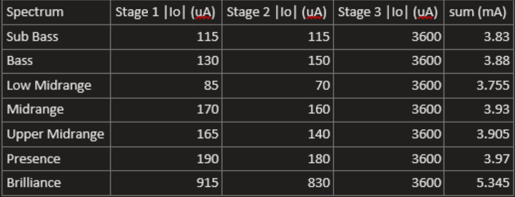
- Calculated max current each filter and internal stage will output when amplitude of input voltage signal is 5V (output at final stage will be saturated to 3.5V):
![]() Say signal was completely in
the Brilliance spectrum, max outputted current would be 5.345mA. The 3.6mA output of stage 3 is
completely due to the 1k ohm resistor of the high-pass RC filter. Assuming each op amp IC which contains 4
op-amps requires 1.5 mA, which there are 6 of -> 6*1.5 = 9 mA
Say signal was completely in
the Brilliance spectrum, max outputted current would be 5.345mA. The 3.6mA output of stage 3 is
completely due to the 1k ohm resistor of the high-pass RC filter. Assuming each op amp IC which contains 4
op-amps requires 1.5 mA, which there are 6 of -> 6*1.5 = 9 mA- 9mA + 5.345mA= 14.345 mA. Negative Voltage multiplier can output a current of 17mA and still stay below 8V, so we are in the clear
Music Spectrum and dB Visualizer
Receive input from a 3.5mm jack, divides the music into 7 frequency bands, shows the loudness of each frequency band in DB using LEDS.
 Ghani Lawal


 Say signal was completely in
the Brilliance spectrum, max outputted current would be 5.345mA. The 3.6mA output of stage 3 is
completely due to the 1k ohm resistor of the high-pass RC filter. Assuming each op amp IC which contains 4
op-amps requires 1.5 mA, which there are 6 of -> 6*1.5 = 9 mA