Dimitar
-
Setup for the electric screwdriver!
05/30/2022 at 10:11 • 0 comments -
Project ideas :)
04/17/2022 at 18:57 • 0 commentsHey everyone, this log is all about how to utilize the parts we have. The designers making the vape pens knew what they were doing. They are small, light and fit in your pocket quite nicely. So here is a list of project that we could take advantage of these properties.
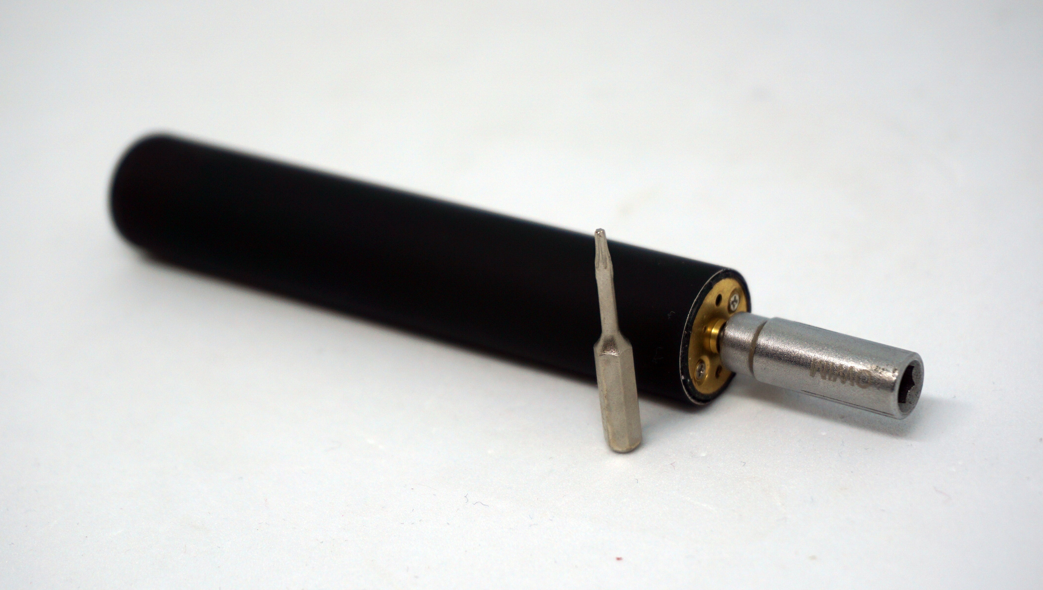
Electric screw driver
This was the first thing it came to mind. The circuitry should not be much of a problem. Two buttons for controlling the direction, charging circuitry and a motor. Of course if we need the motor to wind up slowly and to have battery indication on the screw driver itself, things get a little complicated. The bummer with this project is the bit holder. I had my car mechanic, who happened to have a lathe, turn a cheap screwdriver into the holder you see and make a set screw hole. To be honest I love it. It feels just right. I would love to make it a 3D printed stand with magnetic connectors for charging.
If we change the motor we could defiantly turn this to a micro drill for hand made PCBs or woodwork.
LED Flash light
Another perfect candidate in mine opinion. I found some lenses that fit the bill. This would be the easiest one to happen. Again we need to charging circuitry, nice switch and LED driver. Micro USB for charging and we are good to go.
![]()
Radio clock / Mp3 player
Having a mp3 player as a kid was a big big deal for me. I love listening to music to this day so this is also a strong option. I have changed many devices, I liked the design of one and the sound of another. The ones that look good and sounded great had little battery life. I did not get to have the perfect mp3 player. I found a 0.91 inch display that fit like a glove in the rectangular cases.
Battery bank
One of the cylindrical pens was quite longer then the rest. When I dismantled it the battery was larger and reservoir for the fluid was bigger. We can fit two 560mAh batteries in it for total of 1120 mAh. This is not much, but for sure can get you out of pinch. Having two cells is of course is a bit of a challenge. We need to balance them, so they are charge and discharged equally.
Sensor pod
Again we have durable lightweight case and a battery to fit in it and this is free. I have build a small GPS module 15 by 30 mm. Magnetometers and a gyro sure, temperature and humidity sensors why not! I found those Tiny 2040 by Pimoroni that need a little bit of trim to fit in the case, but defiantly doable.
Foam cutter
This one is the one I have the most lousy concept of all. I need to do some experiments with the wire that is used for vaporizing the fluid. I am almost sure that it can be turn into a small foam cutter.
Which one do you find most interesting or may be you have ideas of yours? Please leave a comment. I really hope that vape pens turn into the next Altoid can. This way we can take thousands of vape pens off the landfills.
Please like and share this project, this means a lot to me.
Cheers,
Mitko
-
Custom BMS
04/05/2022 at 18:13 • 0 commentsSo... why going through the trouble of making a BMS. Simple, because I could not find one that would fit the flat batteries and also I needed to add one anyway for electronic CV project.
![]() ---------- more ----------
---------- more ----------The BMS is based on AP9101C. There are a lot of examples circuits, it is being out for nearly 4 years and you can by it almost everywhere. The last one is very important nowadays. The MOSFETs I chose were DMN601DWK again cheap and easy to find. The schematic is the exact same one that you can find in the datasheet, but still you can find mine here.
There is one very important gacha! You should be very careful which modification you get. Take a close look at "Voltage and Delay Combination" table. Most charger go up to 4.28 V voltage and nearly 1A of current. So if you get something like AP9101cxxx-COTRG1 you will be out of luck. The overvoltage protection will kick in and your battery would not charge. Also when you connect the BMS to the battery for the very first time, you will get 0V. It does not matter if you have fully charged battery. You will need to connect a charger to release the AP9101C from "storage" mode.
![]()
A few word on the design:
- Make it small
- Mark the pads well
- Add 2.54 header pads for the output.
- Make the pads for the battery as big as possible, because the batteries' terminals very
If there is a significant demand I would make them available on tindie. So leave a comment if you want to get one.
Cheers,
Mitko
-
Adding a Battery Management System
04/04/2022 at 19:58 • 0 commentsHey everyone,
If we want to use the batteries we salvage from our vape pens we need to add a BMS to them.
BMS stands for Battery Management System. This system has the role of protecting both the battery and the users. I have made a short video how I am adding such BMS.
---------- more ----------First thing first. How does the BMS protect the battery.
- It detects if too much current is drawn from the battery. This might be the case when we short the positive and negative terminals together or we have a load that is too much.
- It detects if too much current is put into the battery or it is exposed to a voltage that is too high. This happens when incompatible charger is used.
- It protects from over discharge. If the voltage level drops under a critical level the battery might not be able to be charged up again.
- Reverse polarity connection protection. Protect from connecting your charger backwards.
- Some BMS have a storage functionality. It is become more and more common to have devices shipped out of the factories with batteries already inside. To prevent the device from draining the batteries in transit or in storage, BMS disconnects the battery. When the user gets the product it seems dead. But when connecting a charger, BMS releases from storage mode and from then on is business as usual.
Eliminating the risks above, protects the user from LiPo batteries bursting into flames. Also guaranties that we can use our potentially very expensive devices for a long time.
When the battery is used out side of the safe parameters BMS operates two MOSFET transistors that disconnect the offending device. The BMS is always powered and monitoring. When the operation conditions are back to normal the MOSFETs are turned back on and we have power again.
There are many types of LiPo cells and different BMS for each on. So take care to go through the datasheets of both and compare parameters. This is why I am not posting the model I am using.
The most common BMS will have the following characteristics:
Overcharge detection voltage: 4.25V ± 0.05V
Overcharge recovery voltage: 4.05V ± 0.05V
Over discharge detection voltage: 2.50V ± 0.1V
Over discharge recovery voltage: 2.90V ± 0.1VIn other words the BMS will disconnect the battery if it detects voltage higher than 4.25V or lower than 2.50V. And will connect it again when it is between 4.05V and 2.50V. Simple as that. You can also see 1S or 2S 3S etc. 1S is a single cell and 2S, 3S and more are for battery packs. Last but not least is continuous discharge current. Make sure you do not draw more current than your BMS allows. If you overlook this, you may have funny behaviors, Your devices seems to work just fine and then suddenly dies for no reason.
This particular BMS you see in the video I got from my local electronics supplier. It fits nicely to the cylindrical LiPos. I have made my own protection and will add a log specially for it.Now we have safe and reliable power source for our projects. We did that for almost no money and kept piece of electronics away from the landfill.
Cheers,
Mitko
-
Disassembly of a vape pens
03/31/2022 at 10:28 • 0 comments -
The anatomy of a single use vape pen.
03/30/2022 at 19:03 • 0 commentsTo make use of vape pens, first we have to know what we are working with. And the best way to do that, is to take a few of them apart. They come in variety of shapes, colors and sizes, but in essence they have the same parts and operate the same way. It is quite amazing how everything is build to optimize the cost. There are no screws and no glue, everything is snapped or taped in place. The only exception is in the electronics part, where the wires are soldered together.
![]() ---------- more ----------
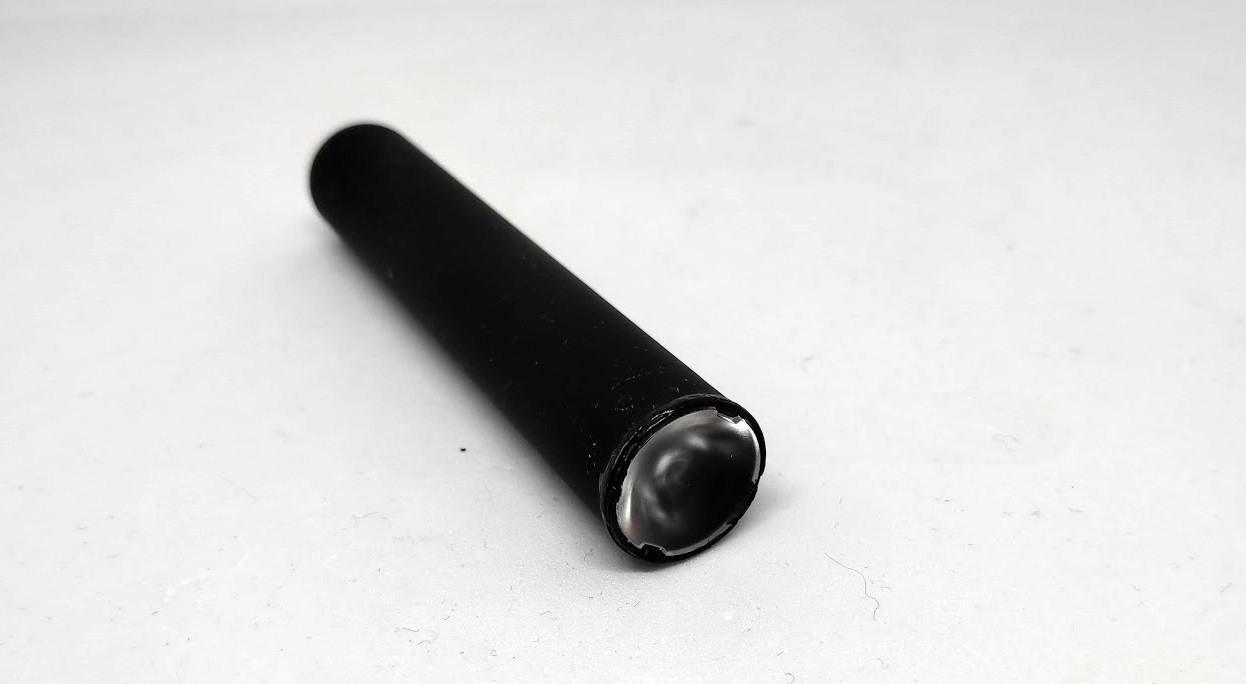
---------- more ----------The outer shell.
![]()
It consist of aluminum extrusion, in our case with a round profile, but it could be square or elliptical. The length of it is 85mm, diameter is 16mm and it comes at 8 grams. It is simple to make, light and somewhat durable. Usually information is printed on it using a silkscreen method. Luckily for us it comes off even when you scrape it with your fingernails. Aluminum is easy to cut and makes for a wonderful project case.
The bottom cap and the mouth piece are both injection molded plastics. They have multiple roles to fulfill. Since this is single use item the designers did not want to waste money making a perfect container for the vape fluid. They knew it is going to leak, especially when the pen is carried in a pockets or bags. The mouth piece has an additional role of keeping the leaking vape fluid inside. To do so, there is a round sponge. Also the shape is made, so it collects the fluid using a lip around the hole. The same kind of sponge can be found on the bottom of the container holding the vape fluid, but not on all models. So far I have not found any use for it.
![]()
![]()
The bottom cap also has two roles. The primary one is to hold the end of the tube shut and the other one is to hold the sensor. You should keep the caps, because later we can use them to hold our projects inside the body of the vape pen.
![]()
Next part gets messy. All of the guts of the vape pen get coated with fluid, so some ethanol and a paper towels are required.
![]()
The container holding the vape fluid is composed of a transparent plastic tube, with a sponge inside. It has silicone caps on both sides. The heating element is in the center of this construction and it is isolated with a high temperature glass fiber insulation sleeve to protect other stuff from the heat. This assembly is from seven parts. The wires have to pass through the tiny holes in the silicon cap. That would not be a great job to have in the factory.
![]()
The brains
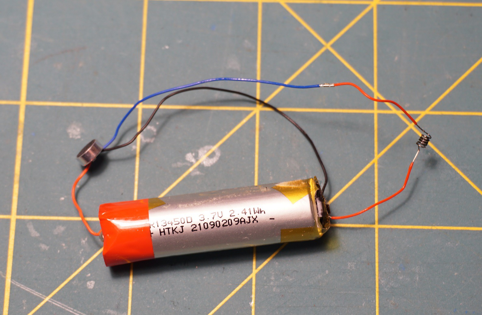
The circuit is quite simple. It contains of a sensor, battery and a heater. The sensor is always power on. This should be taken into account when disassembling, to prevent fires or burns.
![]()
I have drawn the circuitry to make it clearer. The sensor acts as a high side switch in the system
![]()
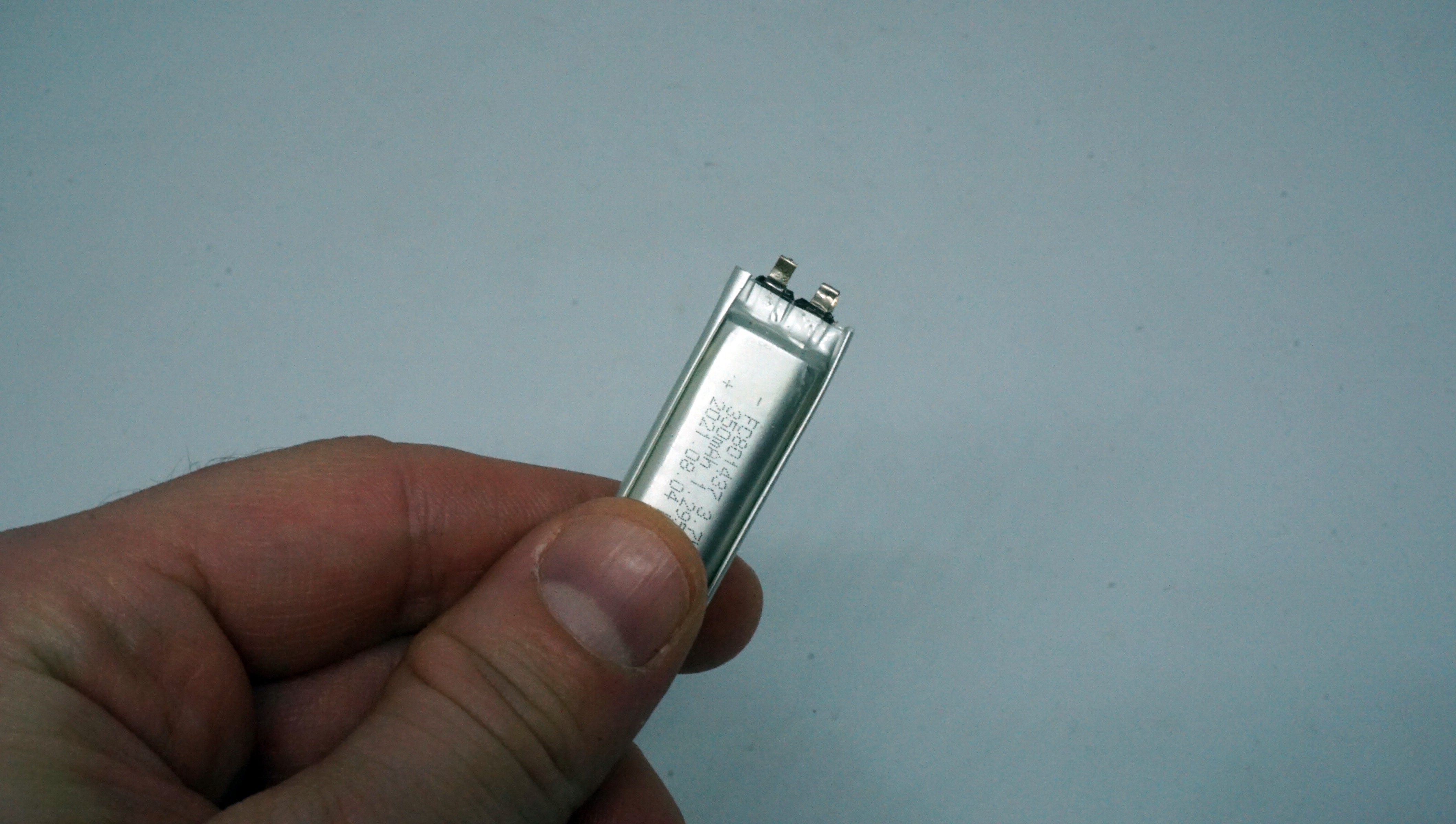
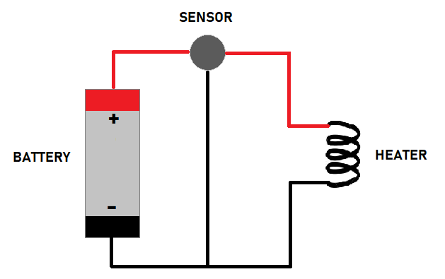
The gem here is the battery. It is a LiPo rechargeable battery, usually between 200 and 600 mAh. So quite nice to have. It is small, but great for sensor nets etc.
![]()
Unfortunately it has no circuitry to protect this battery from overcharge or over discharge. Obviously for the use it has in this devices it does not need this, but for it's new life it will.
This will be the topic of a future post.
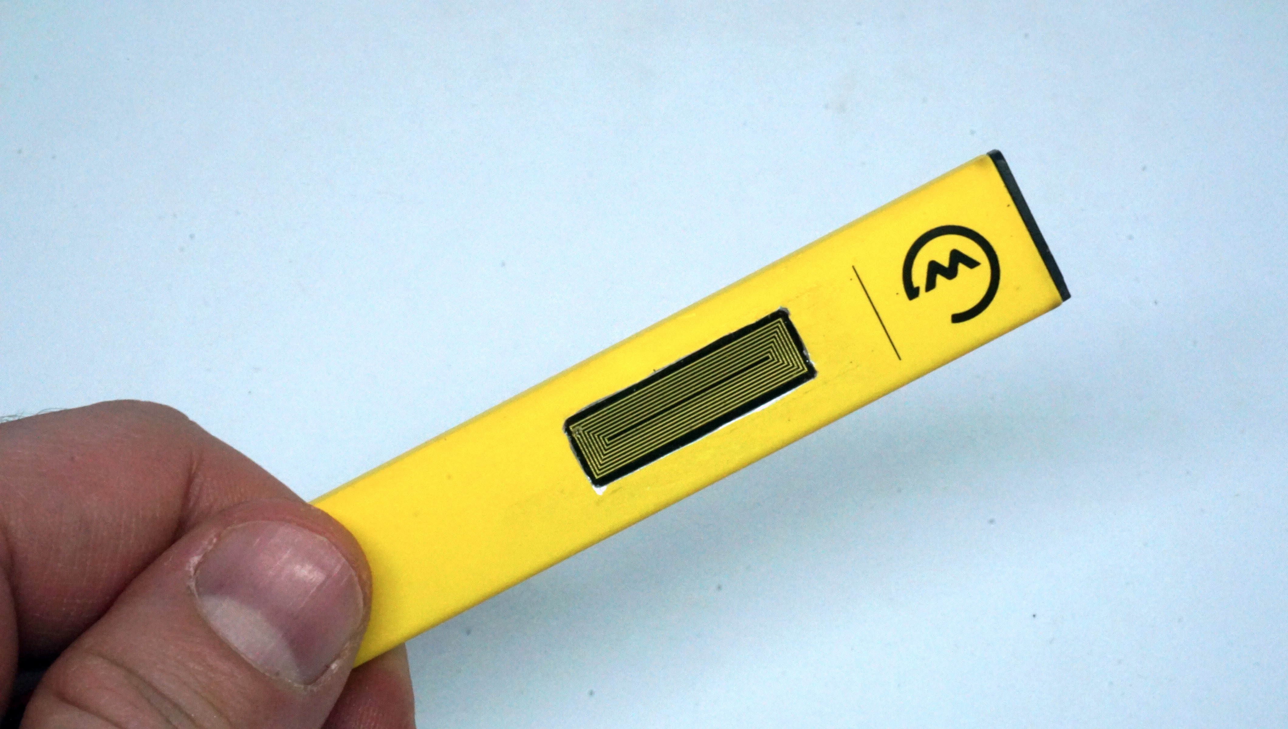
Next we come to the the ASIC or the sensor. It looks like a condenser mic but it is not :)
![]()
There is a YouTube video for you on the subject and a way to reuse this sensor.
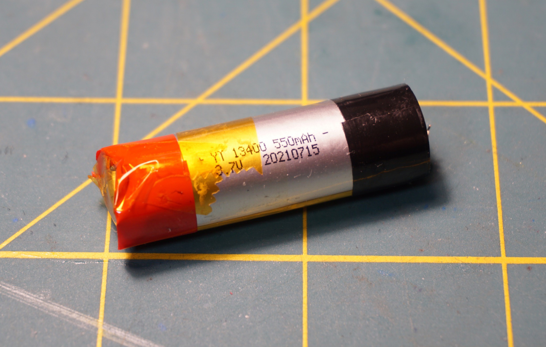
And we complete our tour with the heater.
![]()
My guess it is a nichrome wire. When the vape pen runs it gets as hot as 150 degrease Celsius. It's resistance is 2.4 ohm. I did figure a use for it as well.
More or less the reservoir for the liquid is useless. Every other part I could figure at least one other applications.
Please comment and like the project. There is more to come!
Reusing single use vape pens.
This is a collections of small project you can make borrowing parts from used vape pens.