 Thomas Kremser
-
1Step 1
Thermal Printer configuration/tweak
if you bought the printer over Aliexpress, the seller will ask you which settings you want, then u dont need to do this step. If not read carefully!
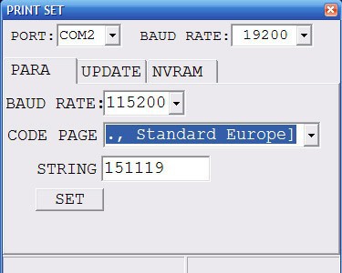
Standard baud rate the printer comes with is 19200 (you could leave it like this and edit the config file to use 19200 as baud rate) but you get better results if you change it to 115200. You need a USB to 5v TTL serial converter for this stepchange the printer baud rate to 115200 and code page US
![]()
-
2Step 2
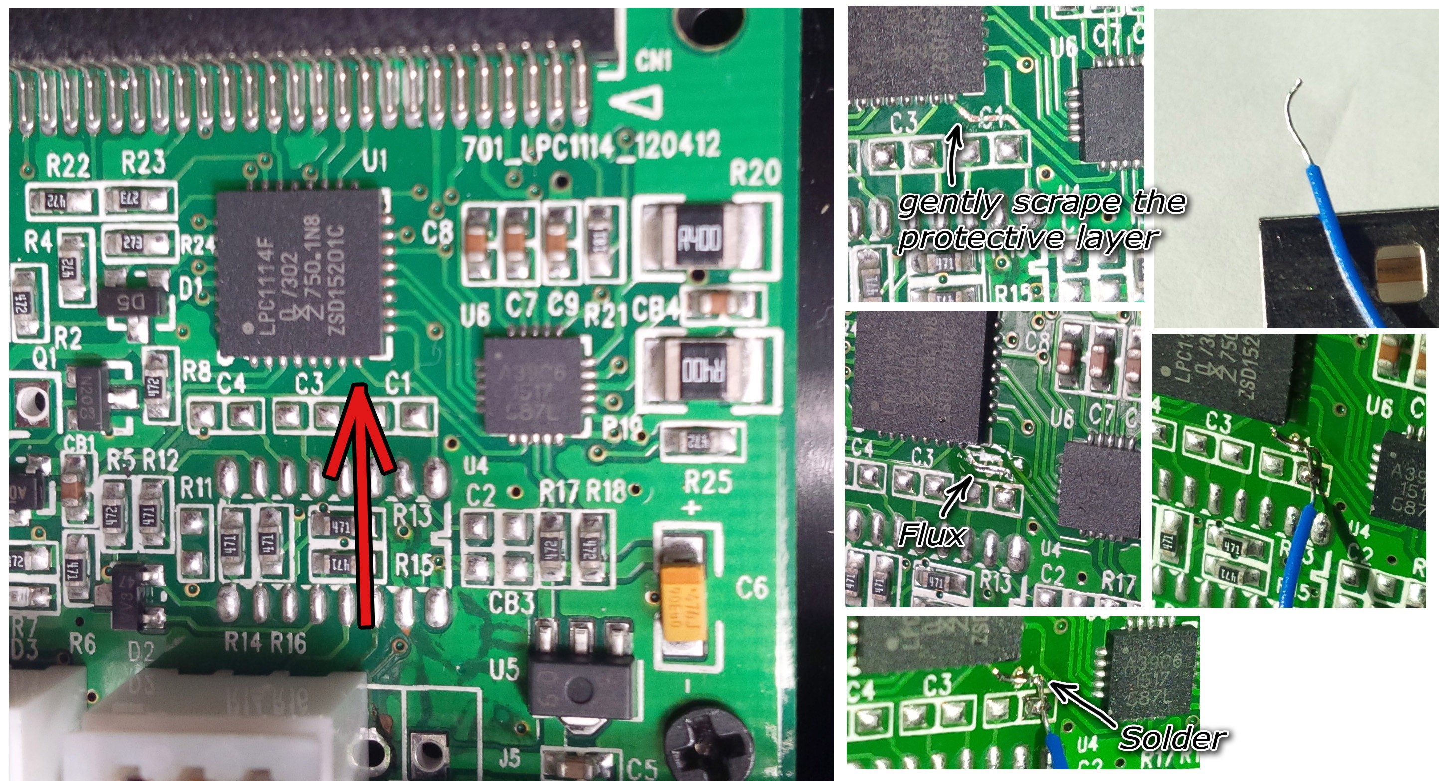
then you have to add a stepper pin which regulates the flow control. Please be very carefully doing the next steps scratch the layer as shown in the pictures.
![]()
-
3Step 3
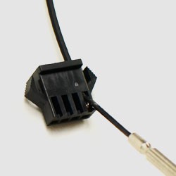
TTL cable modification
cut off the green wire of the TTL Printer or just remove it, use a thin screw driver to unplug it (if you run the printer with 7,4V and attach the Tx to the GPIO of the Raspberry you can damage it, so as it is not needed we unplug/cut it, so there is no risk of destroying your raspberry)
![]()
-
4Step 4
Rasbian Jessie Lite
Pls download the latest version of Jessie Lite https://www.raspberrypi.org/downloads/raspbian/
write it to an SD Card (16GB recommended but 8GB would work too)
boot your Pi, attach ethernet cable (or configure wifi) and enter the following commands
sudo apt-get update
sudo apt-get upgrade
sudo raspi-config
- here you have to enable the camera
sudo nano /boot/cmdline.txtdelete the following (console=ttyAMA0,115200)dwc_otg.lpm_enable=0 console=tty1 console=ttyAMA0,115200 root=/dev/mmcblk0p2 .....should look like this
dwc_otg.lpm_enable=0 console=tty1 root=/dev/mmcblk0p2 ....now we download the files. the original ones can be found on github, but i did modify them a bit (https://github.com/pierre-muth/polapi)and create 2 folders and download the files
mkdir /home/pi/polapi
mkdir /home/pi/Photos
cd /home/pi/polapi
wget https://raw.githubusercontent.com/pierre-muth/polapi/master/jar/config.txt
wget https://raw.githubusercontent.com/pierre-muth/polapi/master/jar/fbcp
wget https://raw.githubusercontent.com/pierre-muth/polapi/master/jar/polapi.jar
sudo chmod +x fbcp
The line after the keyword "WELCOME:" is printed at startup. It could be a space character to cancel it.
The line after the keyword "HEADER:" is printed after each pictures and the keyword "#date" is replaced by the raspberry pi date. It could be a space character to cancel it.
Note if there is a file named header.txt, it will be used for the header.
Please note that the raspberry pi alone doesn't keep the time running after switched off. You can add an RTC clock to solve this issue, by following this nice Adafuit tutorial.
After "SERIALSPEED:" indicate the baud rate of the printer. If slower than 115200, it might be some artifacts on the prints, due to the pauses made by the printer.
After "BUFFER:" is the number of pixel lines sent in advance before the program make a pause to not overrun the printer buffer.
After "DEALY:" is the length in milliseconds of the pauses within the transmission.
After HEATINGMAXDOT, HEATTIME, HEATINTERVAL, is the printer parameters
After CONTINUOUSDELAY, is the delay between the starts of print process when the button is held pressed, including the print time itself.
After RASPIVID: is the camera program parameters, see raspivid website.
After BUTTONPIN, is the name of the GPIO used for the button, according PI4J library.
After MOTORPIN, is the name of the GPIO used for the printer stepper motor read back, according PI4J library.
After SERIALPORT is the name of the serial port com use for the printer, such as "/dev/ttyAMA0". The "#default" mean the GPIO one (ttyAMA0).
After SMALLFONT is an attempt to use the smaller builtin font of the printer.
After -
5Step 5
4D Systems 4DPi-35 installation
do not attach the display yet, install kernel first then shutdown the Pi and attach it.
wget http://www.4dsystems.com.au/downloads/4 DPi/All/4d-hats_4-4-21_v1.0.tar.gz
sudo tar -xzvf 4d-hats_4-4-21_v1.0.tar.gz -C /
sudo nano /boot/config.txt
Find and uncomment the line #dtoverlay=4dpi-35
# uncomment one of the overlays if loading from EEPROM is not supported
#dtoverlay=4dpi-32
dtoverlay=4dpi-35
#dtoverlay=24-hat
#dtoverlay=32-hat
#dtoverlay=35-hat
additionally uncommend this parameter hdmi_force_hotplug=1 in config.txt
shutdown the raspberry, remove the power, attach the display and reboot
-
6Step 6
install fbcp (so you see the console on the GPIO Display)
sudo nano /etc/rc.local
delete everything and add this text#!/bin/sh -e # # rc.local # # This script is executed at the end of each multiuser runlevel. # Make sure that the script will "exit 0" on success or any other # value on error. # # In order to enable or disable this script just change the execution # bits. # # By default this script does nothing. # Print the IP address #_IP=$(hostname -I) || true #if [ "$_IP" ]; then # printf "My IP address is %s\n" "$_IP" #fi
#con2fbmap 1 1 /home/pi/polapi/fbcp & #omxplayer /home/pi/polaroid1.mp4 omxplayer --aspect-mode fill & sudo java -jar /home/pi/polapi/polapi.jar exit 0reboot
now you should see the console on the Display
-
7Step 7
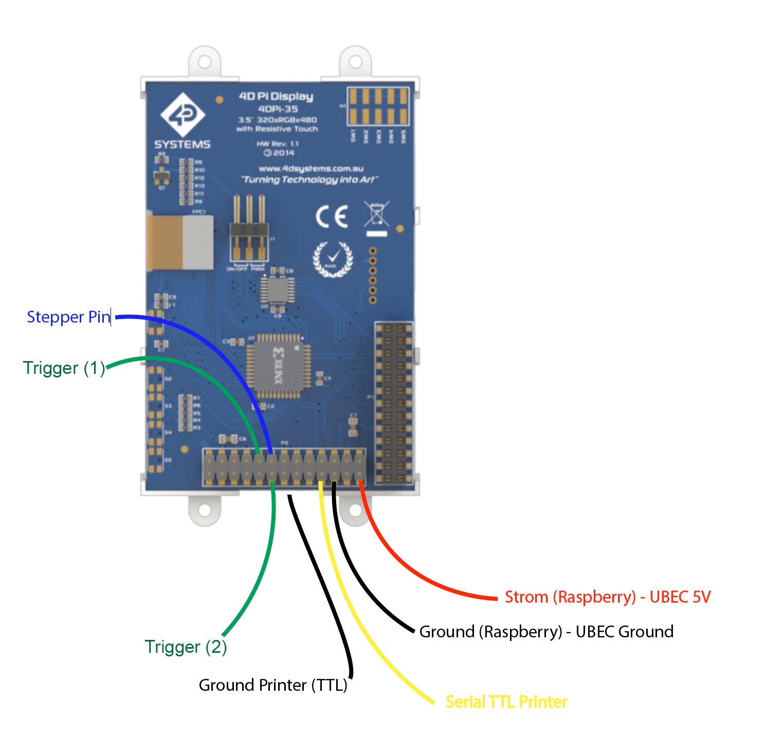
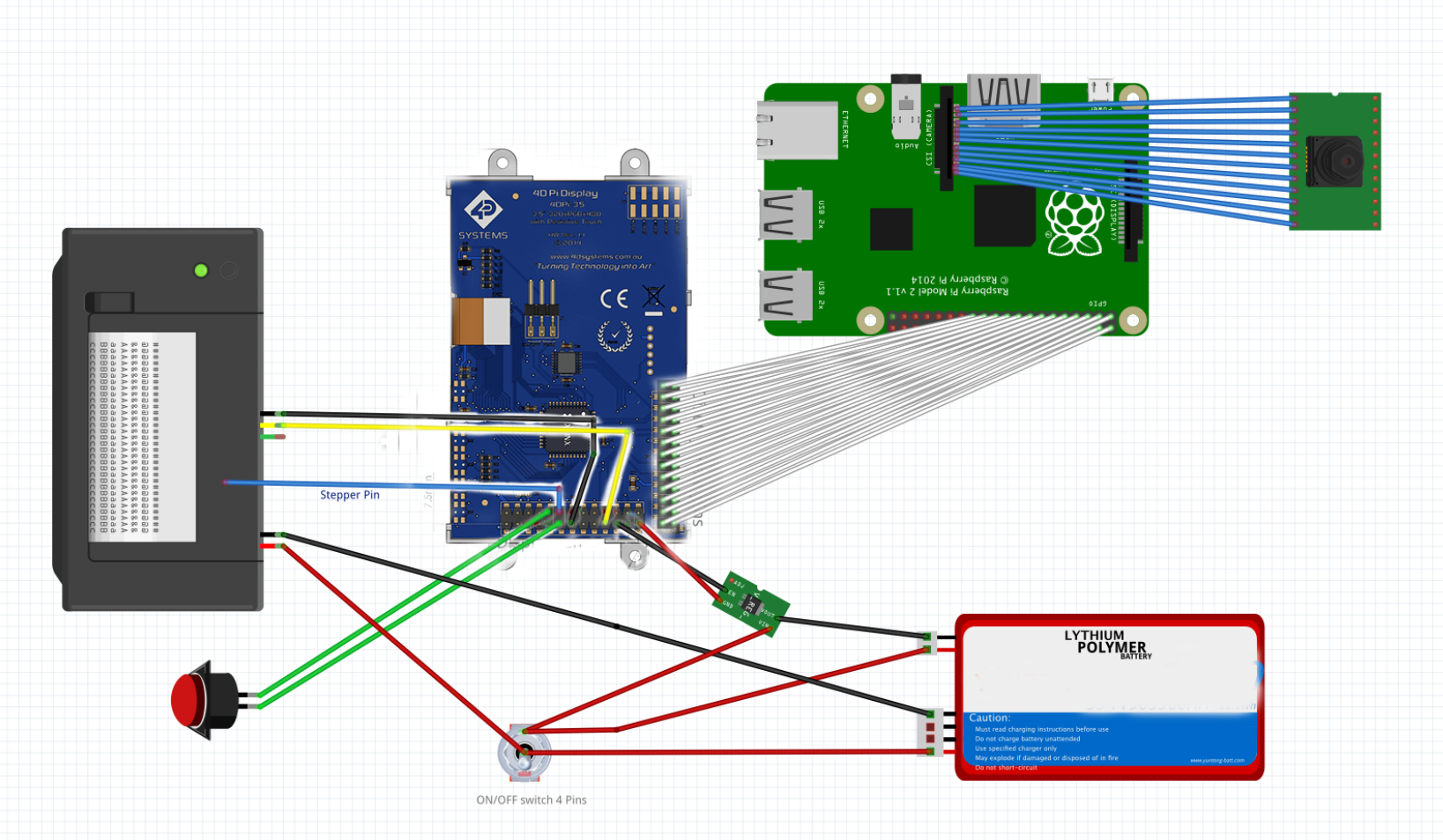
wiring diagram display and printer
wire the display directly or with an GPIO ribbon cable to the Raspberry
and attach the following 7 Pins to the male connectors of the display
DONT ATTACH THE LIPO 7,4V directly, dont forget to solder the UBEC/Step Down so you have 5V 3A (else you will kill the raspberry, trust me :) )![]()
![]()
-
8Step 8
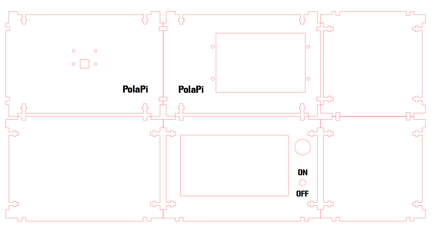
Final Step put it all in a case :D
download the Lasercut File if you dont want to build your own case
here is a preview:
![]()
-
9Step 9
Find the new Case design without Screws in the File Section :)
PolaPi v2.0
inspired by PolaPi (https://hackaday.io/project/7176-polapi) i did an improved version
Discussions
Become a Hackaday.io Member
Create an account to leave a comment. Already have an account? Log In.