 ElectroBoy
I want to make dual power supply unit for my amplifier boards, most of them are of 200w to 400wats. So, I need a stable, filtered and high-power components with durable base. Making of any linear power supply filtering and rectifying circuit is not too much difficult but the components play a huge role.
In this tutorial, we will see how I completed my power supply unit and components used.
Amplifier needs:
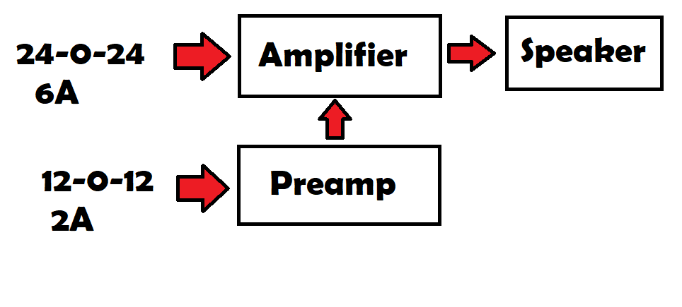
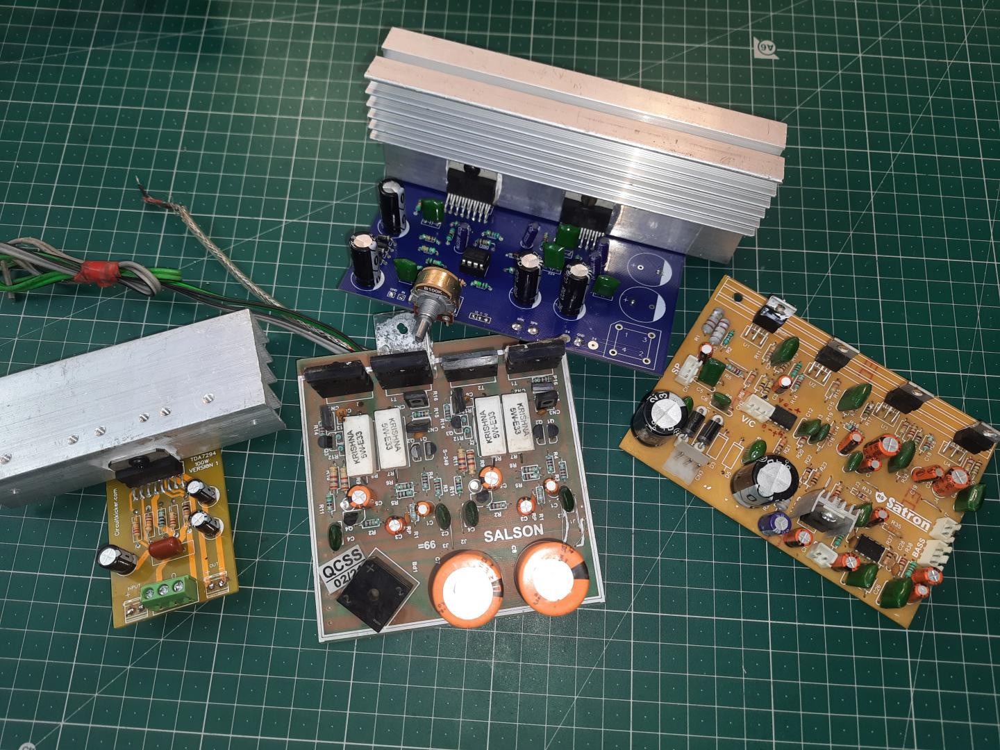
Here you can see I have some stereo and mono amplifier boards, but some of them don’t have good filtration capacitors and proper rectifying unit. And in some of my projects I need dual channel power. 24-0-24 or 12-0-12, with a 3 wired transformer. I want to make a power supply filtration and rectifying unknit that is not only give dual channel but also on different voltages of 12v and 24v.
Components required:
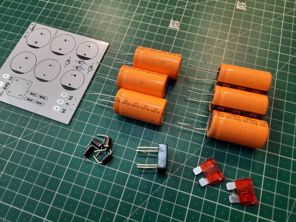
1) BR1010 10-ampere rectifier
2) 10A fuses
3) 24,12v toroidal transformer
4) IN5408 diodes
5) 4700uf/50V keltron Capacitors
6) Custom PCB (JLCPCB)
Transformer:
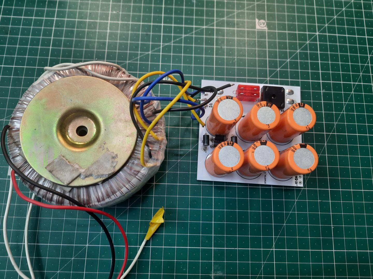
I am using a toroidal transformer, but Iron core also works fine. This toroidal unit works on 220v AC and give output of 24-0-24, 12-0-12 and 0-12. But we need only first two channels of 24 and 12 volts. So, we will make a circuit according to this transformer output voltages with 24 and 12 dual channel power. Maximum current ratings of this transformer are 10Ampere.
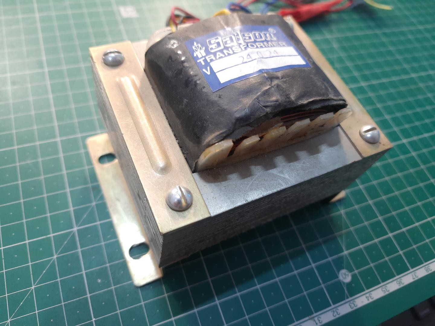
I don’t use Iron core; they are bulky and not too much powerful. Also, the output current and voltage is limited to one or two channels.
Circuit diagram:
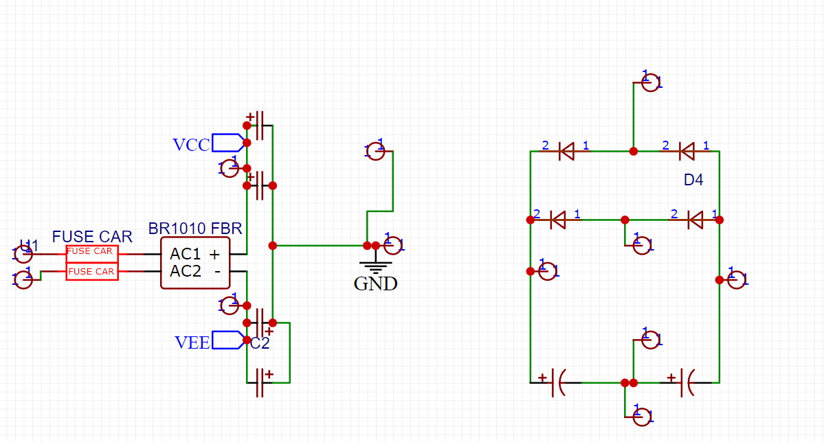
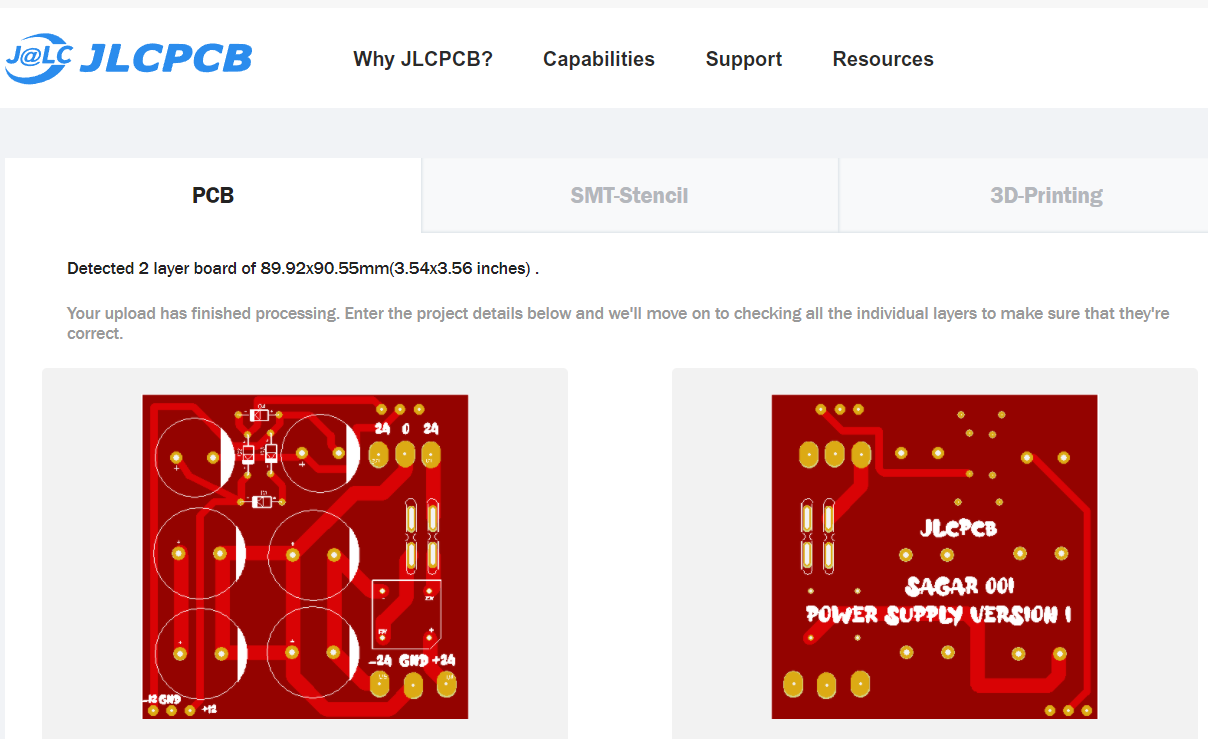
I came up with an idea of making schematics in EasyEDA and here is my designed circuit. This one has 6 filtration capacitors, 4 diodes and 1 big high-power rectifier. The circuit diagram is out of knowledge without connecting points. You can use My files to Order PCB from JLCPCB.
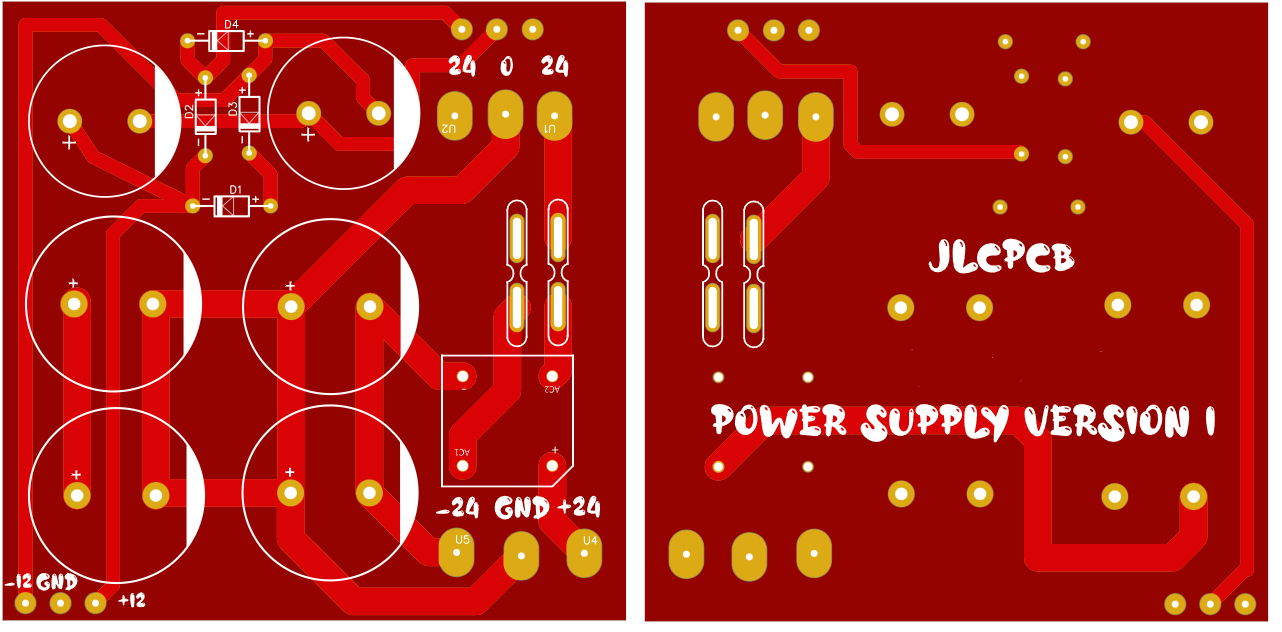
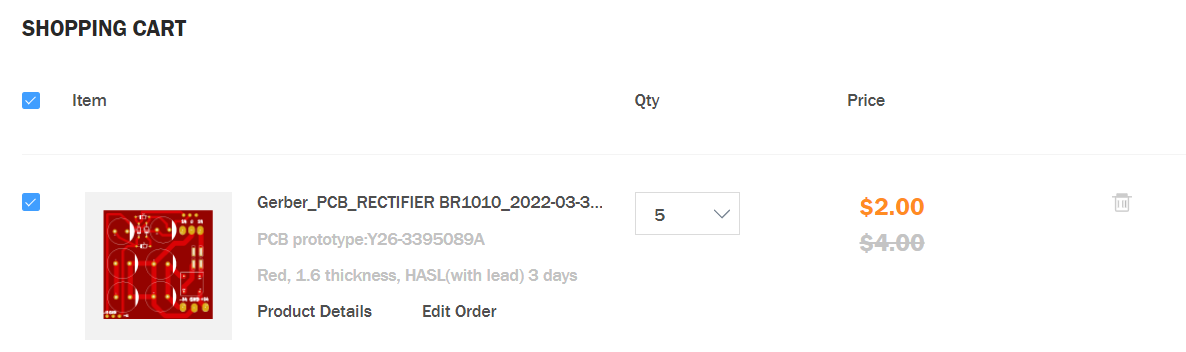
Then we will make a PCB prototype to use this project practically, without PCB all things and circuitry will be messed up and I don’t want to blast or explode anything in this high-power circuit. JLCPCB is sponsoring this project and their PCB prototype service is very amazing, I got the 5PCS of this PCB in Just $2. So, check out to JLCPCB from this link here and get extra reward coupons.
PCB:
Download PCB Gerber files from here.
Sign-up to JLCPCB using this link and you will get free coupons of worth $27.
Circuit description:
we can give two different voltages simultaneously from this circuit in dual voltage. -24 to +24 and -12 to +12. I am using 10 ampere rectifiers for 24-volt operation and 5408 diodes for 12v. Keltron 4700uf 50V capacitors are for filtration, because they are known as best quality highly stable capacitors.
Yep, 10Ampere fuses are mandatory when working with such a high power. These are connected to transformer output, if any short circuit happens the fuses will cut off the supply from main linear unit.
Assembling and soldering:
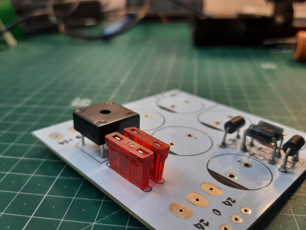
First, I mounted all the diode. I tried to keep them in air so that they can dissipate heat faster.
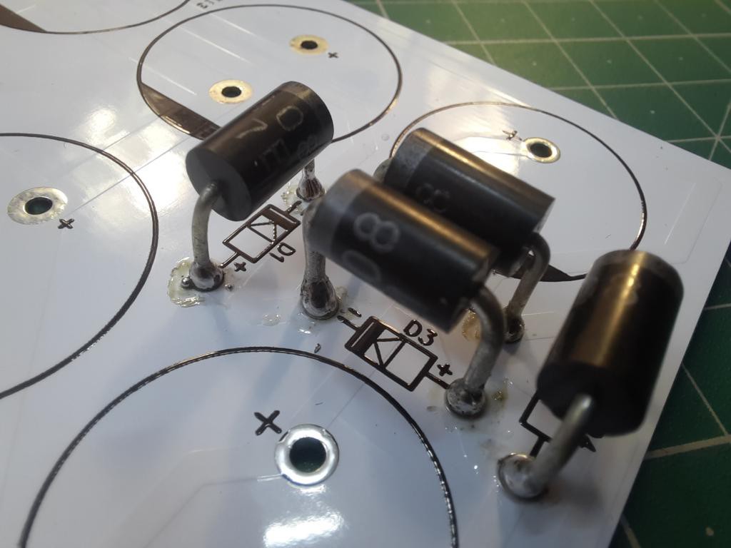
Then I go for main rectifier br1010 (10amps) and fuses.
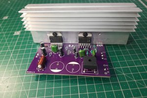
After this I placed all the capacitors and soldered them properly and here are the beautiful looks of this circuit.
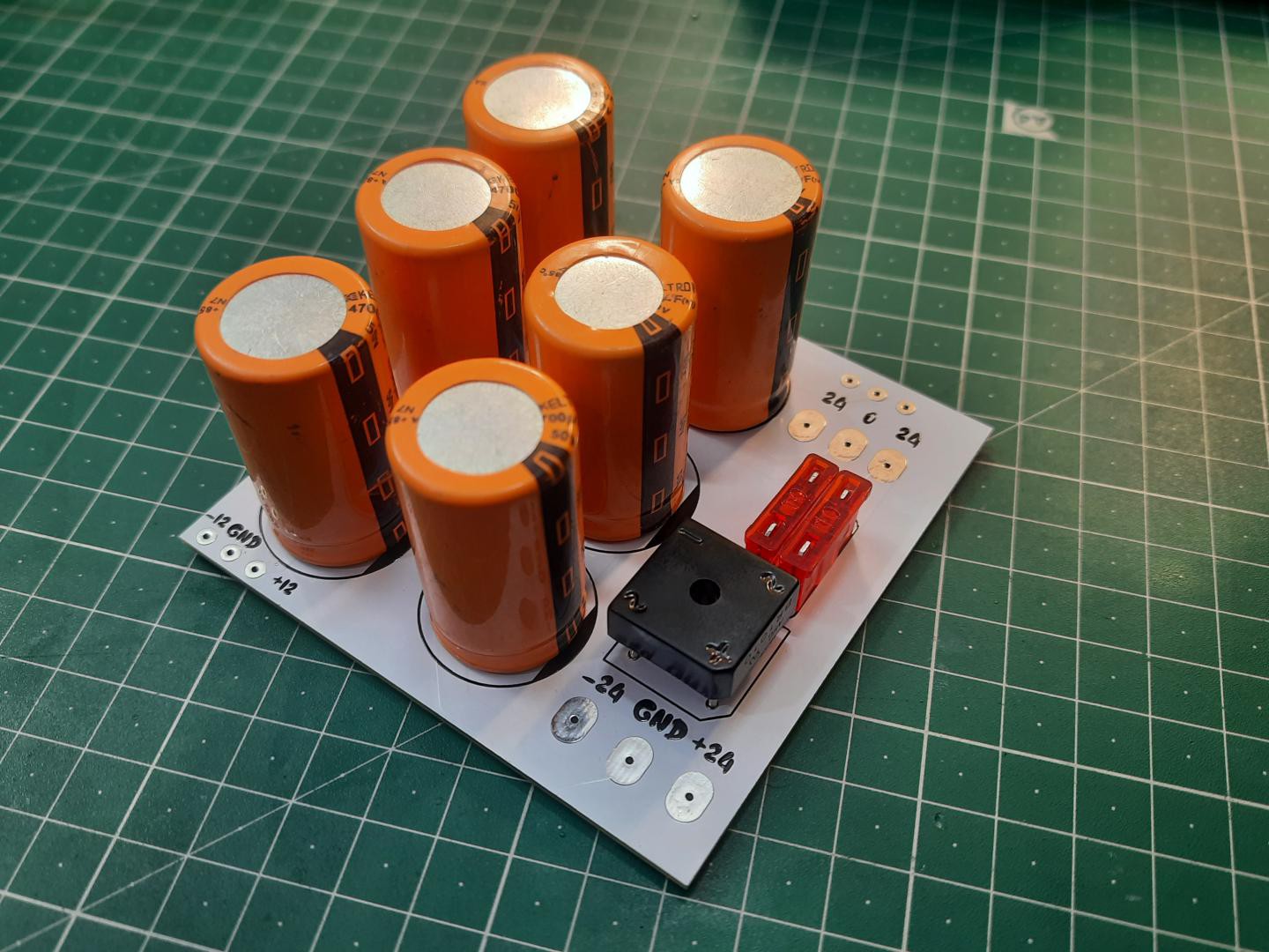
The overall finishing work done by JLCPCB is really very decent in that price and white color is what making it more cooler.
Working: With 12v:
With 24volts:
PCB ordering Process from JLCPCB:
The PCB ordering process is very easy, First sign-up to JLCPCB and upload your Gerber files.
Then choose material, color, quantity, thickness and surface finishing.
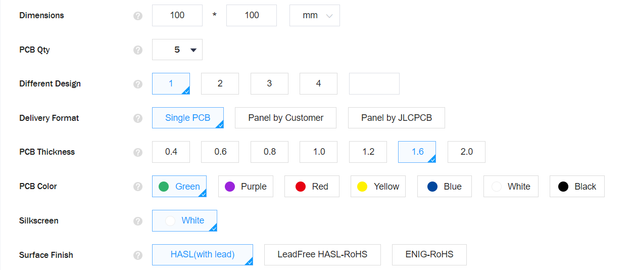
Add your PCB prototype in cart and checkout, you will get the package in just 7 days.
Wants to know more about SMT service then check this post.
 Lithium ION
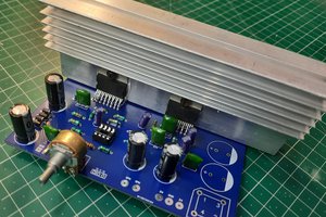
 Sagar 001
another project which mostly serves as JLCPCB advertisement