Overview
The Nano Edition series is a compact Lora device with high efficiency internal compact Lora PCB Antenna, ultra-low noise figure amplifier and internal GPS module. This series aims to balance the RF performance, size, rugged construction and power consumption.
For the firmware, all Nano Edition devices come with pre-installed Meshtastic firmware[1]. Meshtastic Mesh Device Nano Edition G1 also had been supported by the official meshtastic repository on Github. More detials could be found in the The Latest Firmware section. Meshtastic can send off-grid message using inexpensive hardware to create your personal mesh.
The coverage of this credit card size Lora device was tested in the urban area which full of more than 150m skyscraper towers. In the experiment (TX:20dBm, Freq:915Mhz, Medium/Slow), 773m communication distance had been tested, no timeout or re-transmitting occurred. According to the link budget, this system could reach far further than 773m. More details are illustrated in the Real World Testing Section of this document.
Dimension
10cm*5.8cm*1.6cm, ~80g
Typical RF Performance
| Lora Max RF Output Power | 20 dBm |
| Lora External RX Ultra-Low Noise Amplifier (LNA) | Gain = 15.64 dB, Noise Figure = 0.8dB |
| VSWR of Lora PCB Antenna (US Edition) | < =1.5 @ 915 MHz |
| Impedance Bandwidth of Lora PCB Antenna (US Edition) | 882 MHz to 935 MHz for VSWR < = 2 |
| Positioning And Navigation Module | Build-in GPS Module, LNA and patch ceramic antenna. GPS, BDS and GLONASS are supported |
Hardware
| Schematics for Nano Edition G1 | meshtastic_mesh_device_nano_edition_17_mar_2022.pdf | Version: 21 Jan 2022 |
PCB (Nano Edition G1)
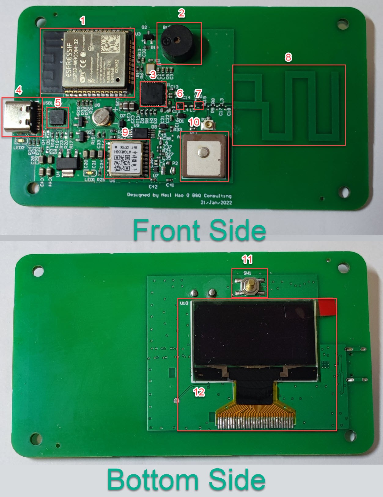
| No. | Description |
|---|---|
| 1 | ESP32 WROOM |
| 2 | Active Buzzer |
| 3 | Semtech SX1276 Lora Transceiver |
| 4 | USB Type C Socket |
| 5 | CH9102F USB to UART Bridge |
| 6 | Ultra-Low Noise Amplifier (LNA) |
| 7 | RF Switch (RF Performance Measurement) |
| 8 | 915Mhz Lora PCB Antenna |
| 9 | ATGM336H-5N-71 Whole Constellation Positioning and Navigation Module |
| 10 | GPS Ceramic Patch Antenna |
| 11 | User Button |
| 12 | 1.3 Inch OLED Screen |
Mechanical Design
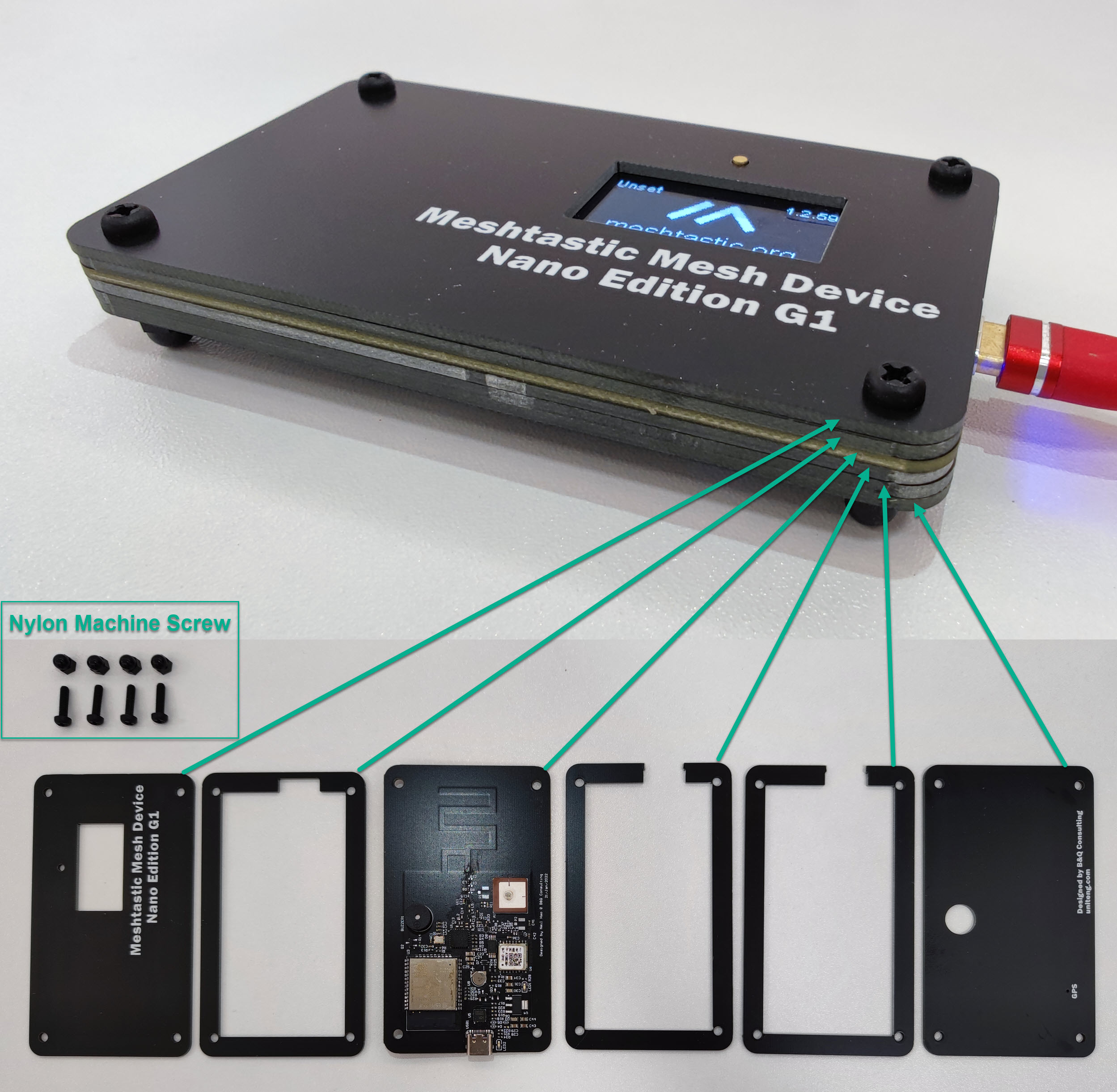 The strategy for the mechanical design is balancing the initial cost and the case BOM cost.
The Plastic case has not been chosen due to relative high initial cost on Plastic Injection Mold. Plastic case usually require a large volume of sales to dilute the mold cost.
Metal cases have relative low initial cost but not easy to deal with the internal antenna.
Thus, the case is constructed by stacking up PCB boards.This method offers a good balance of cost and mechanical strength.
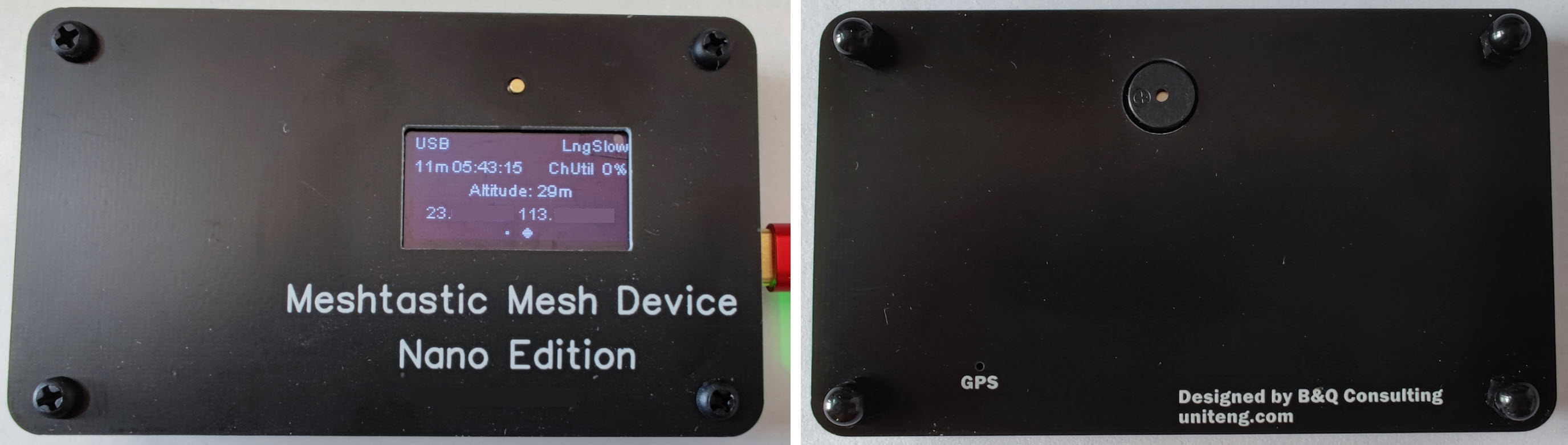 Front Side and Bottom Side of the case.
RF Design - Lora (Nano Edition G1)
TX Circuit and Antenna
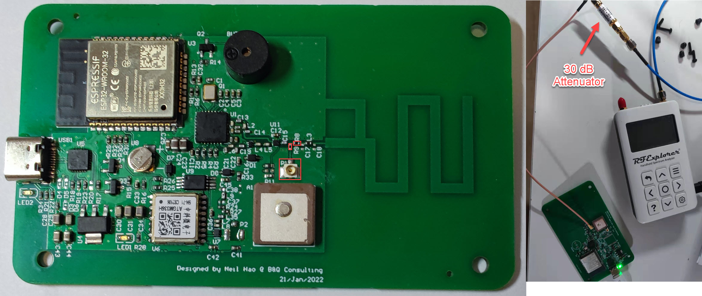
Conduction Test
Instrument Setup and Device Under Test (DUT) configuration
 Click to Enlarge
For conduction test, an IPEX connector needs to be soldered on P1, 0 Ohm 0402 resistor R8 also needs to be moved to the place of R9.
For Instrument Setup, RF Explorer 6G Combo PLUS Spectrum Analyzer and 30 dB Attenuator was used to measure the RF transismission power.
Measurements
 When TX set to 14dBm, according to above result, the RF output power was -14.5+30=15.5 dBm
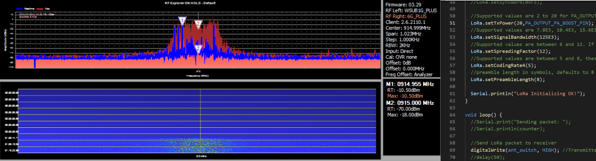 When TX set to 20dBm, according to above result, the RF output power was -10.5+30=19.5 dBm
Summary for Conduction Test
| TX Setting | Measured Output Power |
|---|---|
| 14 dBm | 15.5 dBm |
| 20 dBm | 19.5 dBm |
Antenna Measurement
Instrument Setup and Device Under Test (DUT) Configuration
 Click to Enlarge
For Antenna Measurement, an IPEX connector needs to be soldered on P1, additional one 0 Ohm 0402 resistor also needs to be soldered on the place of R9. C15 need to be removed.
For Instrument Setup, low cost Nano VNA is already sufficient for this measurement. All metal around the antenna will have a notable effect on the antenna performance, so the DUT should be suspended in the air during the measurement. During the test, the...
Read more »

The Meshtastic[1] Mesh Device Nano G1 Explorer represents a significant upgrade to the Nano G1, incorporating the latest RF technologies from B&Q Consulting. The Nano G1 Explorer features a new internal wideband Lora antenna, which supports frequencies from 815 Mhz to 940 Mhz. The wideband antenna, combined with an optimized wideband Lora RF frontend circuit, enables the Nano G1 Explorer to work with the majority of regions' LoRa frequency bands around the world without the need for antenna changes. The design of the device also takes into account the potential effect of the human body on its antenna performance, ensuring optimal RF performance even when carried in a pocket.
The upgrades are summarized in the tab below
RF Upgrades
1. Nano G1 Explorer features a new internal wideband Lora antenna with supports for frequencies from 815 Mhz to 940 Mhz. The optimized wideband Lora RF frontend circuit provides the ability to cover majority of regions in the world without changing the antenna.
2. The device has a new internal GPS antenna that significantly reduces GPS lock time compared to the Nano G1.
3. Lora transceiver has been upgraded from SX1276 to SX1262, resulting in an increase in the maximum TX power from 20 dBm to 22 dBm.
4. SX1262 circuit includes a TCXO (+-1.5 ppm) for improved frequency accuracy.
5. GPS module can be set to a low-power mode with the GPS physical switch.
Other Upgrades
1. Enhanced message notification circuit with the option of LED or Buzzer, configurable through a physical switch.
2. Physical power switch for easy turn on/off of the system.
3. Replaceable OLED screen with a FPC connector.
4. Internal Li-Polymer Battery Charger , an optional 3.7V 603450 JST 1.25mm Rechargeable Li-Polymer Battery could be installed.
5. Buck-boost converter, could provide stable 3.3V to the system even the Li-Polymer battery voltage drops as low as 2.5V. Supply voltage stability is very important to ensure that the performance of RF circuits meets design expectations.
More Details:
https://hackaday.io/project/189665-nano-g1-explorer