 Guillermo Perez Guillen
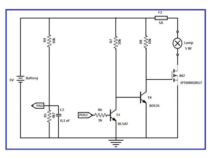
Circuit diagram of the load control
How does it work?
a) Resistors R4 of 10K and R5 of 8K serve us as voltage dividers to measure the charge of the rechargeable battery with our STM32F407VG board. The 8K resistance is achieved with two resistors in series: 4k7 + 3k3. The value of VR5 we obtain it by means of the calculation of a voltage divider, this would be: VR5=(R5/(R4+R5))*VBattery)
b) When the PD12 pin of the STM32F407VG board is up, then the transistor T3 drives and is out of phase 180 degrees. Transistor T4 corrects transistor T3 and puts the original signal in phase with the PD12 pin.
c) To drive the cutt-off and saturation regions to our T3 and T4 transistors, we make the following considerations:
To determine the saturation current, we consider the emitter collector voltage of the output grid equal to zero. Thus: IC=VCC/RC
To determine the cutt-off, we consider that the base current is equal to zero, therefore the collector current is equal to zero: VCE=VCC
d) When the pulse arrives at the "Gate" pin of the IPT60R028G7 Mosfet, then the circuit between "Source" and "Drain" is closed and the 5-watt lamp is turned on. This MOSFET transistor enters the saturation zone when the voltage between the Drain and the Source (VDS) exceeds a fixed value called saturation voltage (Vds sat). That is to say; the MOSFET will be in this region, when:
VGS > Vty VDS > (VGS – Vt).
In the technical sheets of the IPT60R028GT we see that:
Gatethreshold voltage
V(GS)th Minimum = 3
V(GS)th Typical = 3.5
V(GS)th Maximum = 4 V
Therefore, we require 3 to 4 volts in "Gate" to put the Mosfet IPT60R028GT in the saturation region.
e) The protection devices used are the following: Capacitor C2 and Fuse F2.
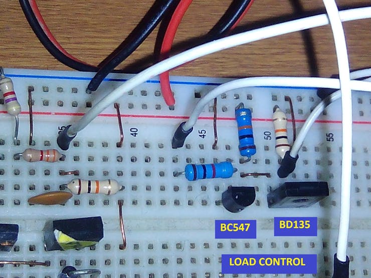
We control the load of a lamp by means of a N-channel MOSFET, and two transistors
Discussions
Become a Hackaday.io Member
Create an account to leave a comment. Already have an account? Log In.