 Guillermo Perez Guillen
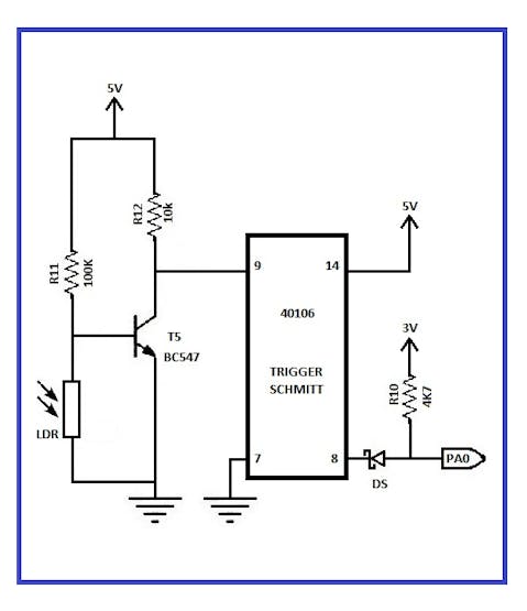
Circuit diagram of the night light control
How does it work?
a) This “Night Light Control” serves us, to know if it´s day or it´s night and activate the lamp. This circuit is powered with 5 volts from the STM32F407VG board.
b) To take control of the lighting we´re making use of a photoresistor or LDR sensor. A photoresistor is made of a high resistance semiconductor. In the dark, a photoresistor can have a resistance as high as several megohms (MΩ), while in the light, it can have a resistance as low as a few hundred ohms. https://en.wikipedia.org/wiki/Photoresistor
c) When there is total darkness, the LDR sensor has maximum resistance (meghoms), the T5 transistor is polarized and at it´s output we have minimum voltage, and at the output of the inverter circuit (IC40106) we have 5 volts. The IC40106 is a Trigger Schmitt inverter circuit. In the following figure we can appreciate how a non-inverter circuit works, which helps us to understand how the inverter circuit 40106 works. These circuits are useful when you want to take control of a digital circuit with signals that are not digital.
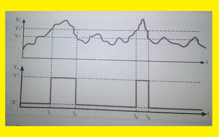
Signals of a photoresistor and a non-inverter circuit
Values of VT and VT- for the 40106 (all values are in volts)

Typical values of a Trigger Schmitt
d) We convert this 5 volts to 3 volts by means of a Schottky diode as shown in the circuit and we apply this voltage to the PA0 pin of our STM32F407VG board.
e) When there is maximum illumination, then the opposite happens. The LDR sensor has minimum resistance, the T5 transistor isn´t polarized and at it´s output we have the 5 volts of Vcc, which enter through pin 9 of the IC40106 inverter circuit. Finally we have 0 volts, which are applied to the PA0 pin of the STM32F407VG board.
f) To drive the cutt-off and saturation regions to our T5 transistor, we make the following considerations:
To determine the saturation current, we consider the emitter collector voltage of the output grid equal to zero. Thus: IC=VCC/RC
To determine the cutt-off, we consider that the base current is equal to zero, therefore the collector current is equal to zero: VCE=VCC
g) On the PA0 pin of the STM32F407VG board, when we have zero volts, then the red LED lights up and the lamp turns off. When we have 5 volts the green LED turns on and the lamp turns on.
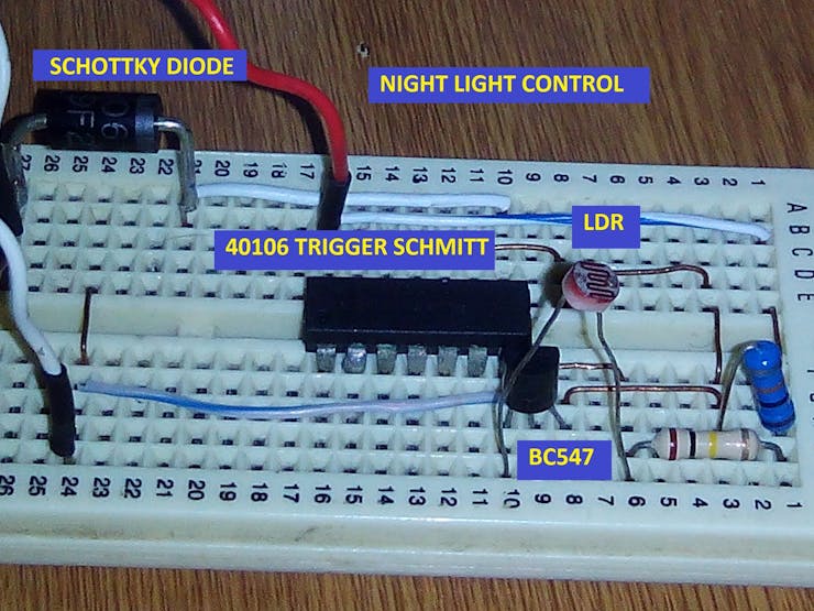
You must ensure that the photoresistor is free of obstacles to detect light
Discussions
Become a Hackaday.io Member
Create an account to leave a comment. Already have an account? Log In.