James Newton
-
Update to Setup and Software
10/16/2022 at 14:44 • 1 comment![]()
Hi Folks,
I've added some components and files to this project that I used to speed up the whole Screen Blink to Microcontroller communications. There might be some remnants from all my testing that are no longer required.
I changed the "protocol" from I2C to what I'm calling TwoWire. I'm sending 8 bits at a time, MSB first (makes it easier to see what data was send on a scope or logic analyzer), with a small delay between bytes.
Any comments/suggestions/corrections/money will be appreciated ;-)
/Aram
-
Swap logic levels for circuit with pullup.
09/08/2022 at 18:48 • 0 commentsAssuming the use of a photo sensitive resistor between the analog pin and ground, and an internal or external pullup resistor to the power rail, a white screen will cause a low voltage, and a black screen will allow the voltage to rise. So, to make this the default (as it's the simplest circuit possible, consisting of only the sensors plugged into the Arduino header) I've swapped the black and white blocks on the test web page, but I also made it easy to switch back with a couple of "defines" at the start:
  var logic1 = black
  var logic0 = white
https://github.com/JamesNewton/JamesNewton.github.io/commit/f36116a8cec1beee6d23ae3cc618ed002eca941c
Next steps (please help if you can?): Update the Arduino code below to decode the I2C start, data, stop and check for reliability of communications. The time required for the serial output to dump all the data into the plotter far exceeds the timing of the actual binks, so it's good to set the analog levels, turn that print off, and only output the digital signal and decoding. -
A start on the Arduino code
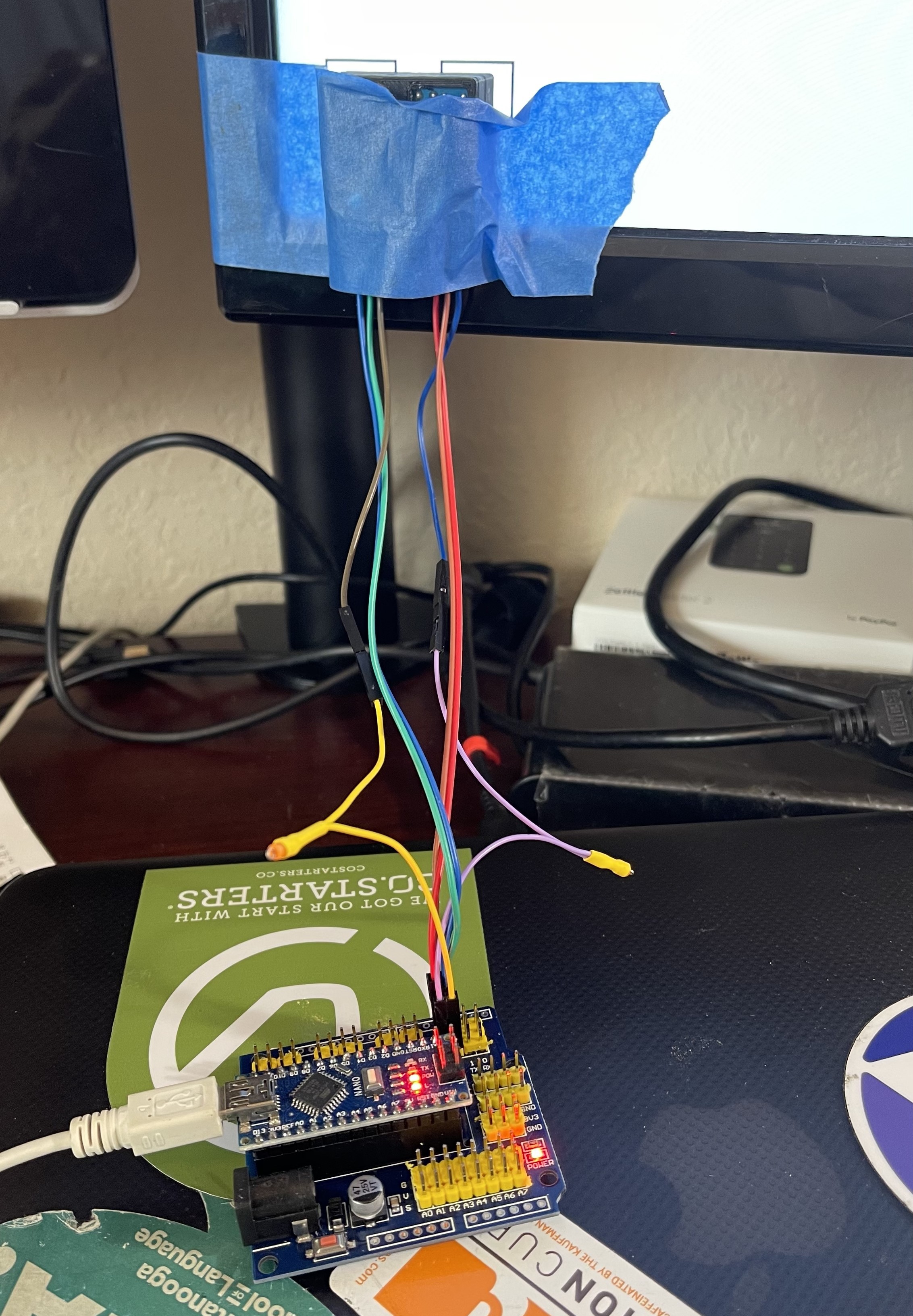
08/27/2022 at 21:43 • 0 commentsThis code reads the A2D pins from the sensors, tracks the middle of the signal range, chops that into a high or low signal, and displays all that for the Serial Plotter so you can debug the setup.
The sensors in this case are nothing more than photoresistors using the internal pull up in the Arduino. (Yes, the analog pins in the Arduino CAN have a pull up enabled). The total hardware cost outside the Arduino are a pair of light dependant resistors. (!)
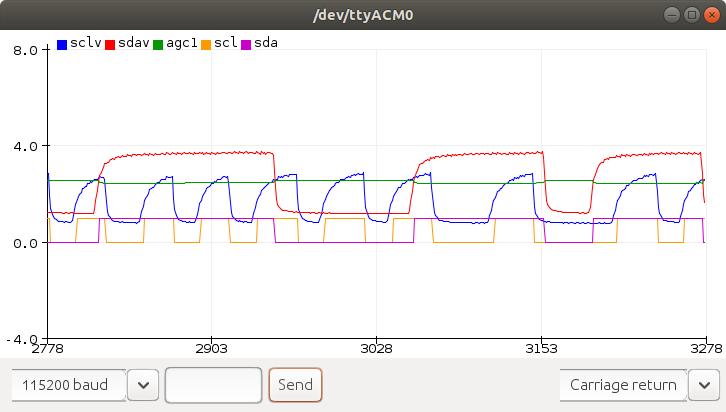
Here is a sample: The red is the data, with the green showing the cutoff point / AGC (Automatic Gain Control). You can see the slight increase on agc when the signal goes low, and the decrease when it goes high. That provides some hysteresis to avoid "bounce" or multiple edges. The blue is the clock, which also has an AGC, but it isn't shown here. Note the difference in signal levels caused by different positioning of the sensors to the screen. The yellow and purple are the resulting SCL and SDA signals. I've not yet decoded those to retrieve the data. The data is coming from this page:
https://jamesnewton.github.io/webbot.html
and the source for that page is
https://github.com/JamesNewton/JamesNewton.github.io/blob/master/webbot.html
(not the free secure web page hosting from github and the ability to access the phone camera inside the browser)![]()
Here is the code, such as it is. Much work remains to be completed, and I will NOT have time for it. I really hope others will pickup and run with this.
/* ReadAnalogVoltage Reads an analog input on pin 0, converts it to voltage, and prints the result to the Serial Monitor. Graphical representation is available using Serial Plotter (Tools > Serial Plotter menu). Attach the center pin of a potentiometer to pin A0, and the outside pins to +5V and ground. This example code is in the public domain. https://www.arduino.cc/en/Tutorial/BuiltInExamples/ReadAnalogVoltage */ #define SDA_CHANNEL A0 #define SCL_CHANNEL A1 #define FILTER 256 float agc0, agc1, hi1, lo1; float hysteresis; bool scl, oscl, sda, osda; bool pause; // the setup routine runs once when you press reset: void setup() { // initialize serial communication at 9600 bits per second: Serial.begin(115200); pinMode(A0, INPUT_PULLUP); pinMode(A1, INPUT_PULLUP); //good starting values for midpoints, highs and lows. agc0 = 2.0; agc1 = 2.0; hi1 = 3.8; lo1 = 1.1; hysteresis = -0.1; scl=sda=oscl=osda=0; pause = 1; } // the loop routine runs over and over again forever: void loop() { int sensorValue0 = analogRead(SCL_CHANNEL); //clock on A1 float voltage0 = sensorValue0 * (5.0 / 1023.0); int sensorValue1 = analogRead(SDA_CHANNEL); //data on A0 float voltage1 = sensorValue1 * (5.0 / 1023.0); scl = (voltage0 > agc0)?1:0; if (scl != oscl) { //clock line changed agc0 += scl?hysteresis:-hysteresis; //noise suppression oscl = scl; //update } agc0 = ((agc0*FILTER) - agc0 + voltage0)/FILTER; //sda = (voltage1 > agc1)?1:0; if (voltage1 > agc1) { //data high hi1 = ((hi1*FILTER) - hi1 + voltage1)/FILTER; sda = 1; } else { //data low lo1 = ((lo1*FILTER) - lo1 + voltage1)/FILTER; sda = 0; } if (sda != osda) { //data line changed //agc1 += sda?hysteresis:-hysteresis; //noise suppression hi1 += sda?hysteresis*2:-hysteresis*2; //noise suppression osda = sda; //update } //agc1 = ((agc1*FILTER) - agc1 + voltage1)/FILTER; agc1 = (hi1 + lo1)/2; if (Serial.available() > 0) { // read the incoming byte: Serial.read(); //clear it but toss it pause = pause?0:1; } if (!pause) { Serial.print("sclv:"); Serial.print(voltage0); Serial.print(", sdav:"); Serial.print(voltage1); Serial.print(", agc1:"); Serial.print(agc1); Serial.print(", scl:"); Serial.print(scl); Serial.print(", sda:"); Serial.print(sda); Serial.print("\n"); } } -
Optical Flow
05/18/2022 at 22:33 • 0 commentsI happened upon some brilliant code on github for doing optical flow in the browser. Open this URL in your smartphone, then go to the "Zone" demo (the Pong one is fun but doesn't give the detail to show what is happening). Allow it to access your camera, then instead of moving your hand, as instructed, just tip the phone slowly left and right, as if it were being moved on a robot. Note that the yellow dot does a good job of tracking rotation.
https://anvaka.github.io/oflow/
If you move too fast, it loses track, but that can be adjusted, and for a slower moving (careful) version of the bot, it might be just fine, at least when combined with the compass and other sensors in the phone.
The code is open source (note the Fork me...)
Just another example of the amazing robotic control things that can be done in a smartphone browser without installing anything.
-
Less complex (1 component) "circuit"
05/16/2022 at 16:02 • 0 commentsI purchased a set of these sensors for $10+ on Amazon:
The GL5528 seems to work best, just plugged in between pin 7 and ground. Then I set pin 7 as an input with pull up and was able to sense light and dark, just passing my hand over the sensor.
TODO:
- Add another channel for the clock
- Write some Arduino code to show the state of those pins on a graph and try different transmission speeds to see if the signal gets through at "fast enough" rates.
- Try the wire library to see if I can receive I2C data
My time is stretched to the breaking point right now so if someone wants to help out by duplicating this and doing those steps and sharing the code / results I would be VERY appreciative.
-
Auto power up on SmartPhone insert
04/12/2022 at 17:26 • 0 commentsAdd a microswitch at the bottom of the slot where the SmartPhone is inserted so it automatically powers up the bot when the phone is inserted.
The script on the web page can listen to it's accelerometer sensors and send commands for short forward and back bursts to the motors in opposite directions; e.g. try to twist back and forth. If the sensors don't see that pattern, then the phone isn't in the robot or the bot isn't sensing it correctly. E.g. the phone will know it's in "not inserted" mode and keep sending that pattern looking for motion.
On power up, the bot will expect to see that pattern and will use it to set levels on the A2D. This will compensate for different screen brightness, lighting conditions, alignment, etc... Once it configures, it will start moving, and the phone will feel that "I'm in! Switch to ready to go mode"
If during normal operation, a motor command doesn't generate the expected motion, it can initiate a test "twist" and if that fails, switch back to "I'm out!" mode.
Web Smart (Phone) Screen Blink Bot
Secure web page on smartphone safely drives cheap bot with flashes of light using internal sensors and web services.