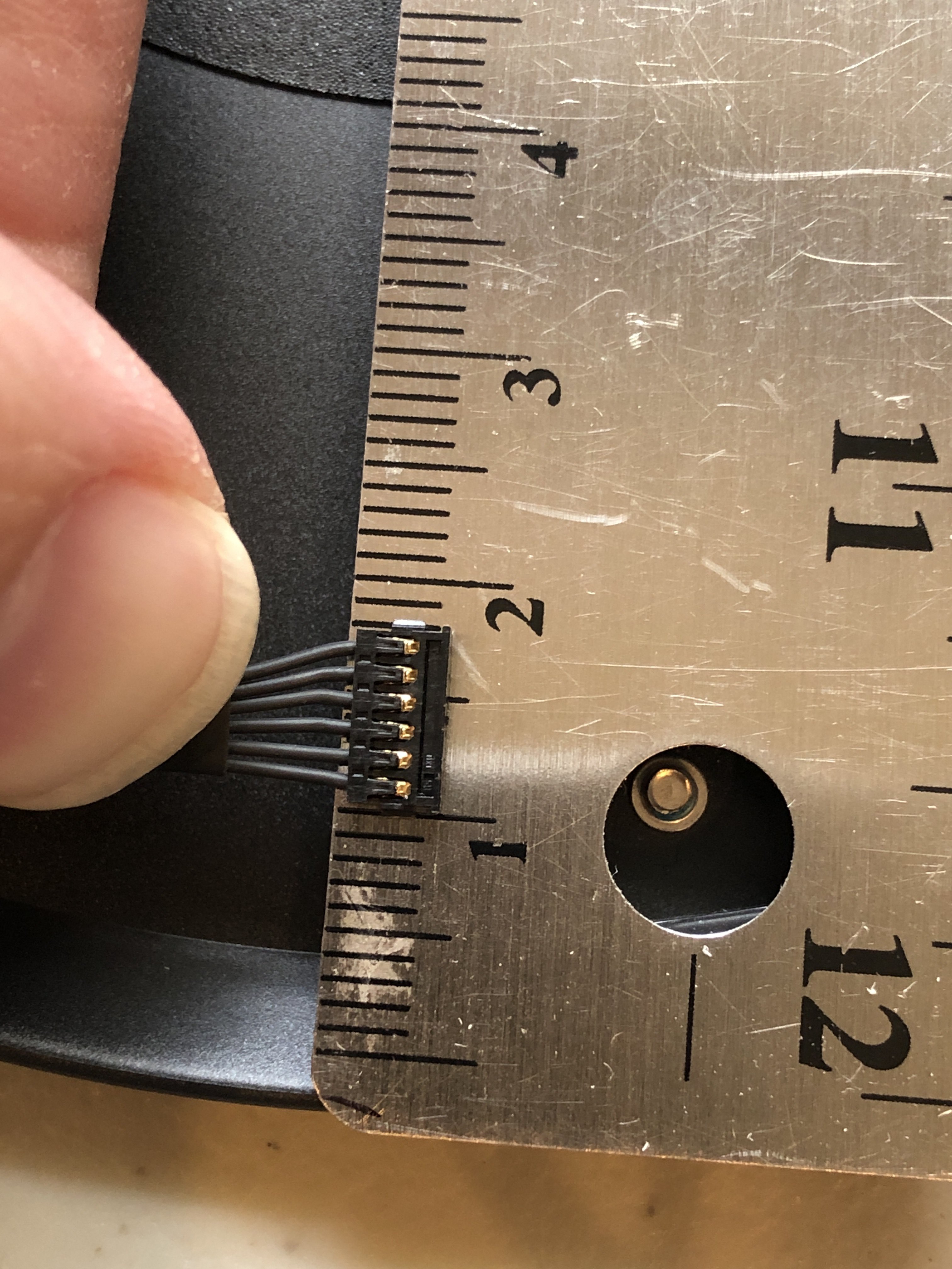
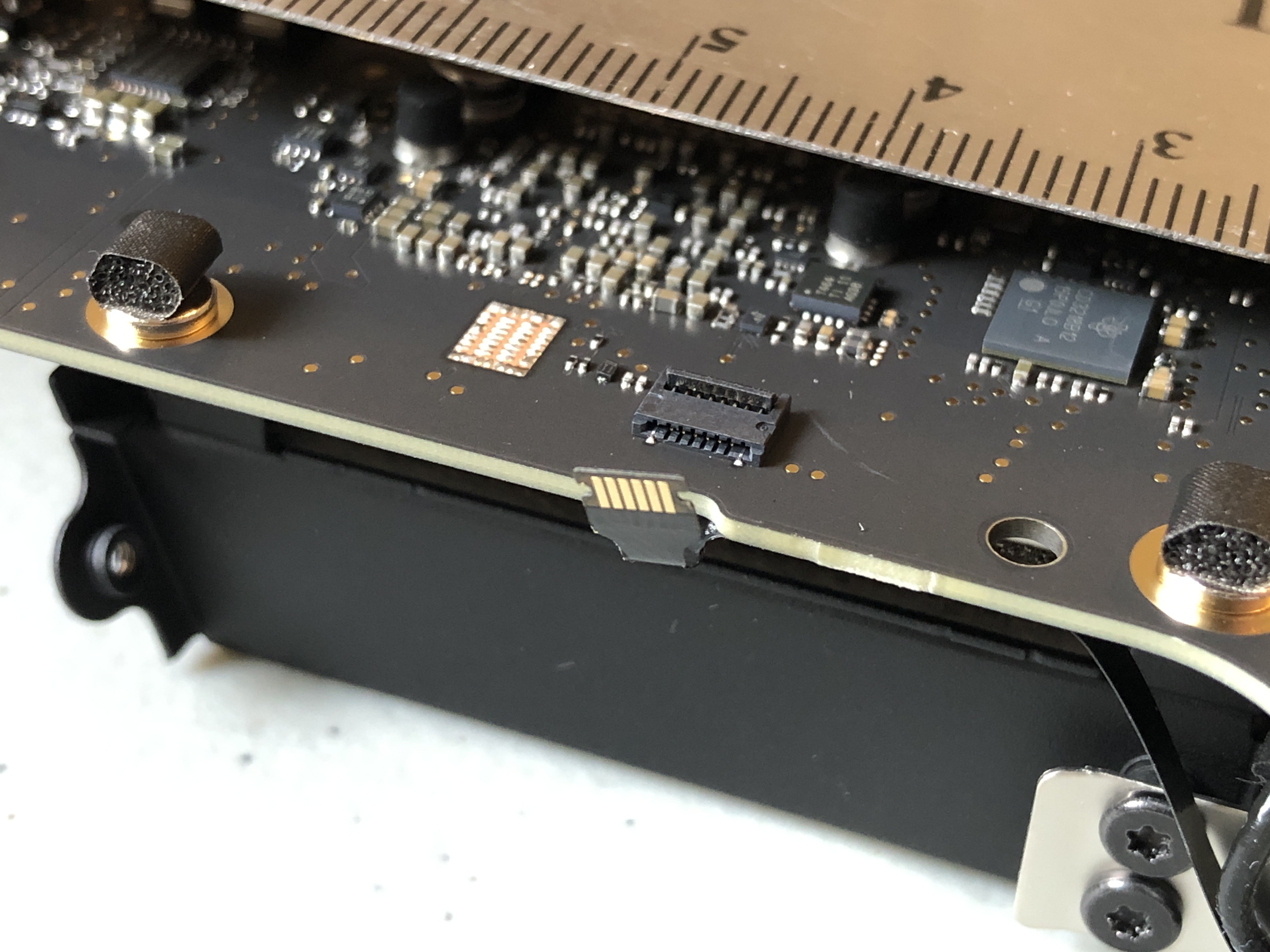
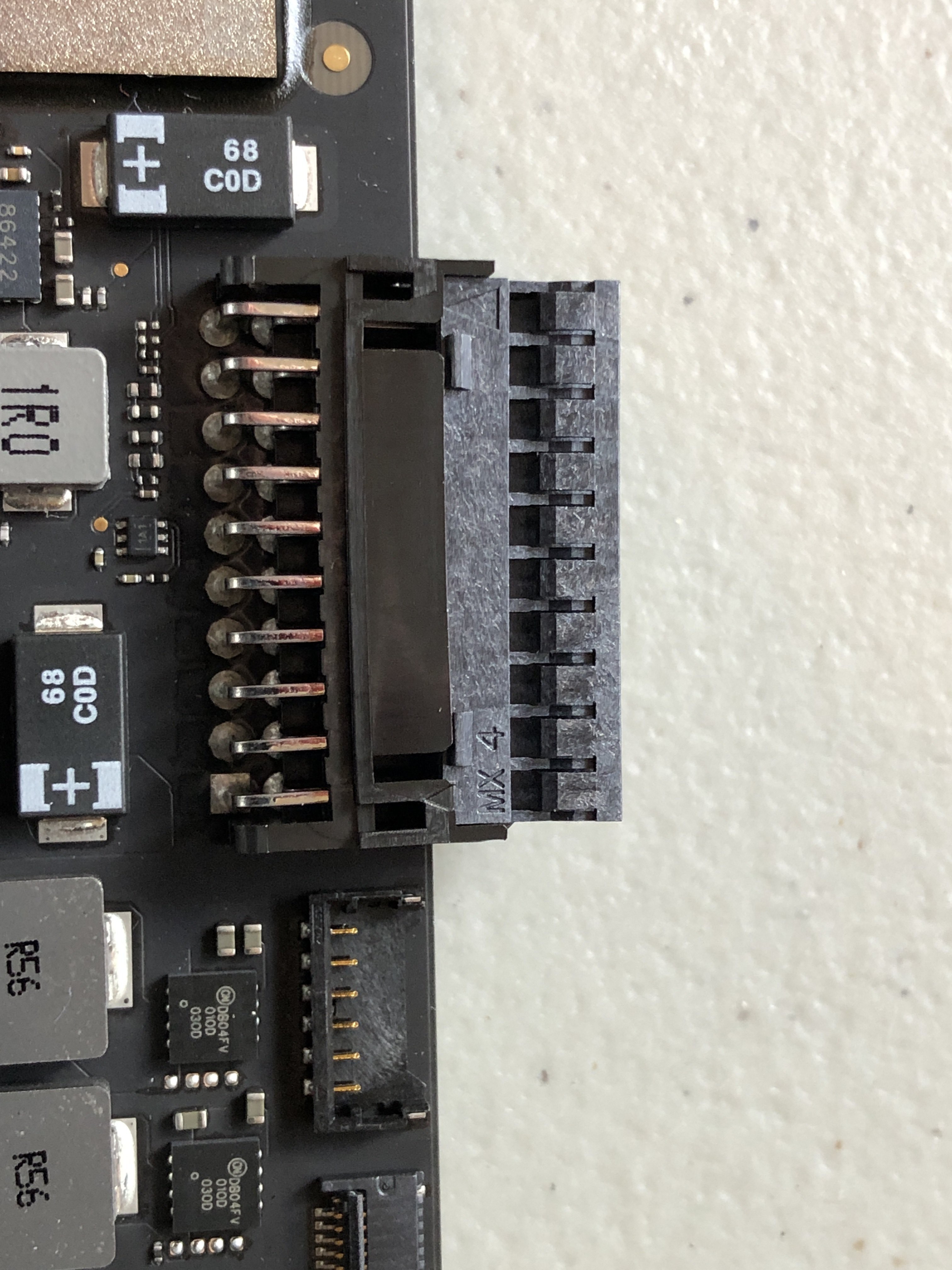
The G4 iMac is considered by many to be one of the most beautiful computers ever made, but its 2002-era internals leave something to be desired. Many people have successfully brought these computers into the future over the years with new internals or turning them into external displays. The most daunting portion of this process has been the conversion of the on-board TMDS connector to a more usable HDMI or DVI connector.
I'm developing a PCB that will turn the internal display connector into HDMI without having to disassemble any cables. As with any project, this is built on the shoulders of those who've come before. Most notably here, DremelJunkie, who created many of the English-language guides for the conversion process.
I finally reassembled the iMac today to make sure the display was working. Good news first, it seems to be working fine. Bad news, during the eighteen months or so since I last booted it up something got frazzled in the HDD and it isn't seeing the disk.
I'm thinking I'll take it back apart and try reseating the IDE connector another day just to be sure and then give installing a fresh copy of Sorbet Leopard a shot. Since I'm not planning on reusing the G4 for anything it's not a huge deal, but it would be neat to record a quick bit of video of the computer running under PPC power before I switch it over permanently.
This started as a project to provide a simple connector to the TMDS cable of the iMac, and quickly ballooned into a full blown M1 iMac G4 conversion kit. While I am planning on doing the full conversion kit at some point, for the purposes of this project page, I'm reigning things back into just the display connector. It's the linchpin for the larger project, and should be useful for any other mods people want to do to the machine, not just dropping Apple Silicon inside. Hopefully, this will keep me from getting bogged down in connector searches and other miscellaneous rabbit holes that have thwarted my progress thus far.
Finally got a chance to pull the Mac mini apart to start investigating the connectors on the logic board.
First up, the fan connector. This looks to be a 6 pin molex connector. I haven't had a chance to figure out which line is which, but am hoping to scope it out soon. Speculation from some friends includes +/- 12V, speed sense, and maybe some temperature sensing for the different lines.
The power button is connected over a 6 pin FFC cable to an 8 pin board connector that apparently only actually uses 2 pins (source: "iMac G5 upgraded to iMac M1"). The thickness of the FFC cables is 0.21 mm. It looks like the LED and IR sensor FFC is the same 6 pin cable although I'm not certain if it's the same length. The board connector is also 8 pins, although it looks like the on-board connector is attached a little differently than on the power connector. I'll have to look the next time I get it apart.
The 20 pin PSU connector was identified by some people over at iFixit working on 12V conversions, and it is almost the right connector. The keying slots (?) aren't quite the same. The Molex connector keys are short and square while the OEM is long and skinny. The pins do line up, so I think if I trim the connector it will fit in alright, but I'd love to find a better match if anyone knows of one.
So, I looked through the schematics and the 26 pin “kitchen sink” or “blind mate” connector should be a 16 pin connector. Apparently something changed between when the drawings were made and when the computer went into production.
I found the 26 pin version of the molex connector specified, but it doesn’t look like the connector on the board. I’m wondering if this was something special that Foxconn made for Apple, or if I just need to look a little longer.
I’m only just starting with this. I’ll try with the 17” I’ve got, and if it works well, I’ll try to get the 15” and 20” going as well. The first task was tracking down the 21 position board connector, which I’ve found on DigiKey: JAE Electronics / FI-W21P-HFE. The board connector is actually shielded, but I haven’t been able to find that variant. The spec sheet is for all of them at once, so part numbers have been tricky to figure out (at least for a newb like me).
Second step is to trace the wires from the LCD to the board connector and cross reference with the pinouts on the display from Dremel Junkie’s website. I haven’t found a pinout for the board connector, and I want to make sure the cable doesn’t switch any of the pins on its way through the neck.
*This is my first project on here, and this was supposed to be the first log entry, but I put it in the project description instead. Whoops.
Got a box of goodies from DigiKey the other day, but I think I ordered the wrong 26 pin connector for the inverter/speaker/fan. The big one in the picture is the one on the board, and the tiny one to the right is the part I ordered. Some of the spec sheets don’t have the connector dimensions which makes things extra fun.
I was able to track down a copy of the board schematics, so I’m hoping there’s a BOM there with part numbers, but I haven’t had a chance to dig into it yet.
Today I finally got to tracing the lines from the TMDS connector on the LCD to the board connector. I need to double check everything before I commit to the board layout, but my preliminary findings are below.
Interesting! I wasn't notified about your earlier comment about the pin outs. I think Dremel Junkie should have everything you need for it though? Is that why you're just doing the header pins for now so you can test it?
LMK if you want to be added to this project and maybe we can consolidate our efforts into one spot?
I think this has gone stale. I am going to create some TMDS to HDMI breakout boards and do some wire wrap. I do need the pinouts for the TMDS port however. Can anyone help?
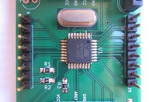
Awesome can I buy this anywhere?