Well updates here certainly dried up a bit, but I've still been making some slow progress.
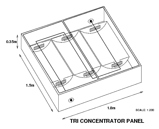
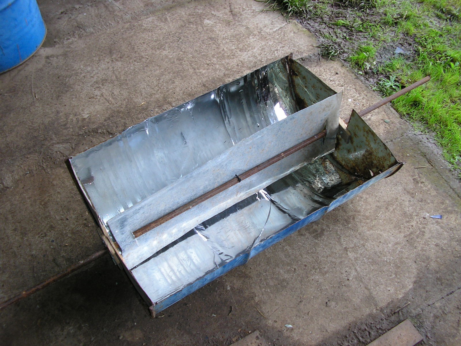
The window dimensions weren't as advertised, so the design was revised to this three-concentrator box:
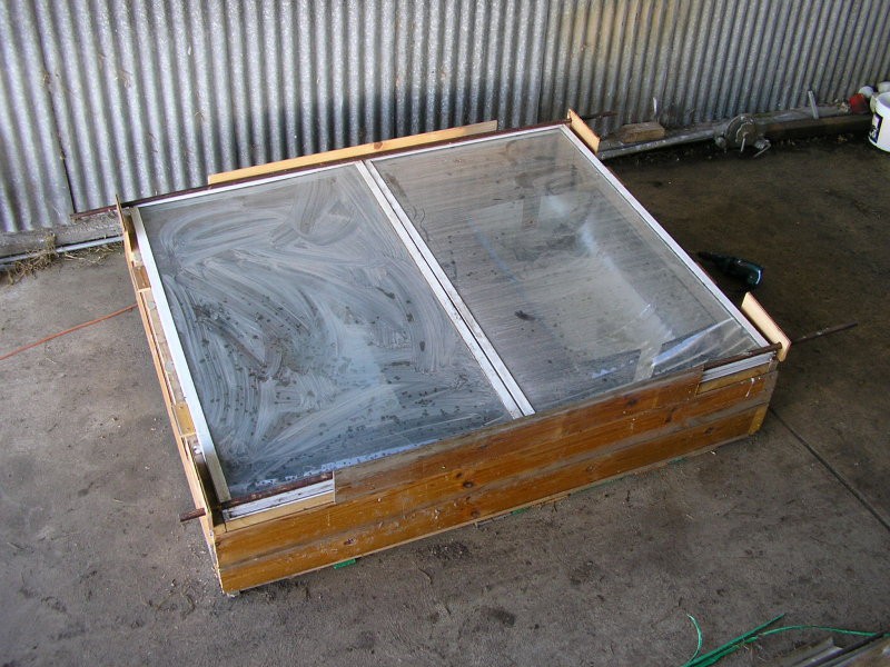
Which I've now built, but not before the windows got very dusty, as you can see.
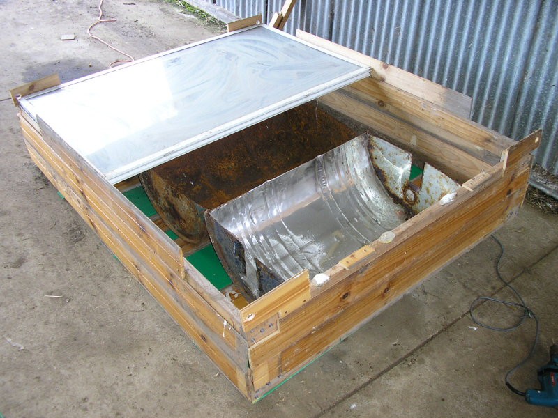
Inside only one of the reflectors is usable, the drum that I was going to use for the other two turned out to be too rusty inside, so I need to cut open another one.
So the next step is to prepare two more reflectors with the chrome vinyl wrap and collector panel, then it's time to start on the plumbing.
After digging through my collection of scrap building materials, I've revised my plan for mounting four concentrators in a box together down to three. It turns out that I've got at least twelve 2.4m (8') lengths of 4x2" pine, but only one length that's over 3m, so removing one concentrator brings with width down to 2.25m and saves me from needing extra joins or materials.
So for the three-concentrator panel, the general parts list is as follows:
2.4m 4x2" pine x8
Corflute, or wooden slats, for sides x? - should have plenty of either already.
44gal drum x2
1,500x750mm windows in aluminium frames x3
1/2" threaded steel pipe, 1,100mm long x1
1/2" threaded steel pipe, 1,300mm long x2
1/2" threaded steel pipe, approx. 500mm long (depending on elbow joint) x2
1/2" steel pipe elbow fitting, female-female x4
1/2" gate valve x1
Tank x1
Connecting hose for tank and associated fittings for gate valve
Chrome vinyl wrap, 1,520mm wide x1,500mm
Adheasive foam seal material x12m
Galvanised steel sheet metal for collector panels, 900x290mm x3
Matt black or blackboard paint for collector panels
Nuts, bolts, screws, nails, etc.
OPTIONAL: Ceiling insulation material (try adding this after completion)
Pine lengths will be cut as follows:
2.25m x4 (4x 0.15m left-over)
1.5m x4 (4x 0.9m left-over)
0.35m x4 (from 2x 0.9m, 2x 0.2m left-over)
To Buy:
Windows
1/2" threaded steel pipes
1/2" steel pipe elbow fittings
Chrome vinyl wrap
Adheasive foam seal material
The most important parts which I don't already have are the windows, because they set the dimensions for everything else (and I'm not entirely confident in the dimensions stated in the advertisement). So before buying/building anything else, my first task is to bite the bullet and buy those.
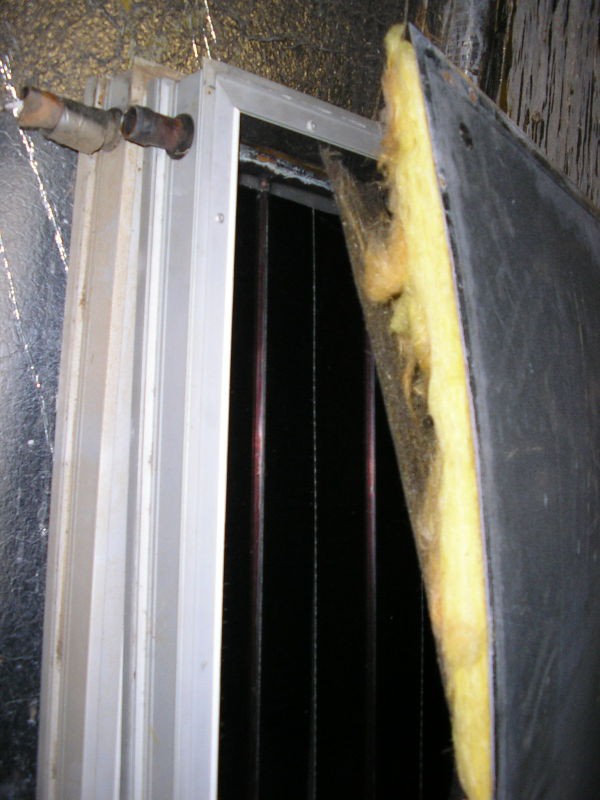
Looking inside the solar hot water panels, it's interesting to see how simple they are. Copper pipes are sandwidched between black annodised fins, similar to my collector panel design, and these heat up from direct exposure to the sun through the glass. The back is insulated.
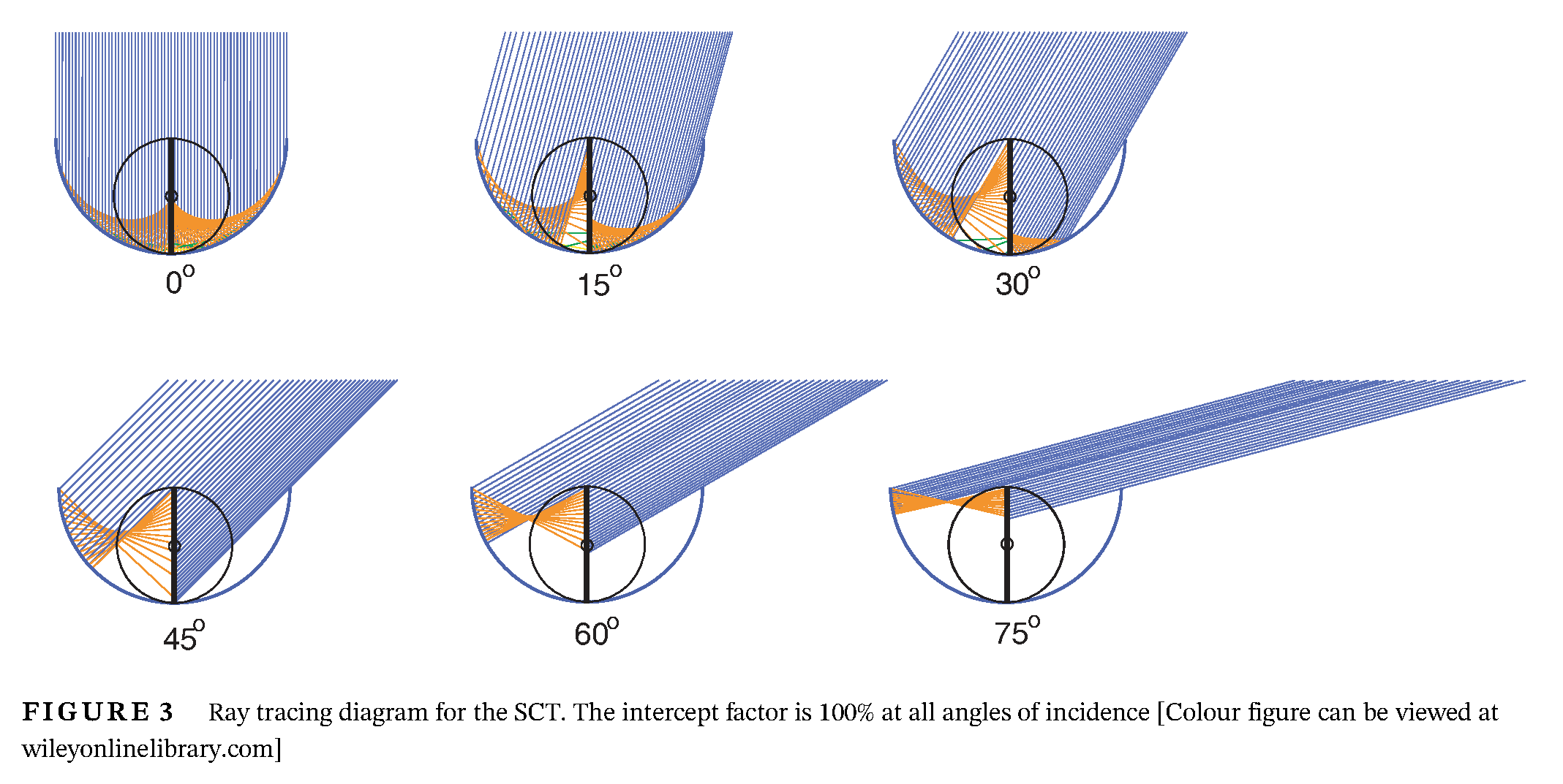
The approach of using multiple connector panels and smaller pipes in parallel could be applied in my design. The diagram below is from the semi-circular solar concentrator research paper that I mentioned earlier, and shows that when the sun is at some angles, half or more of the collector panel is unlit. Testing has revealed how this results in a significant heat loss - with the unlit section acting as a heatsink and drawing heat away from the pipe. In such cases the unlit section is noticably colder to the touch compared to the pipe.
This problem might be reduced if multiple smaller collector panels and pipes were run next to each other, and colder/unlit sections were shut off to prevent drawing heat away from water passing through the hotter, lit, pipes.
But this would make the design much more complex, and probably require lots of high-temperature solenoid valves. It also wouldn't help as much on cloudy days where the light is diffused and therefore incident from a wide range of angles. So I won't pursue it at this stage.
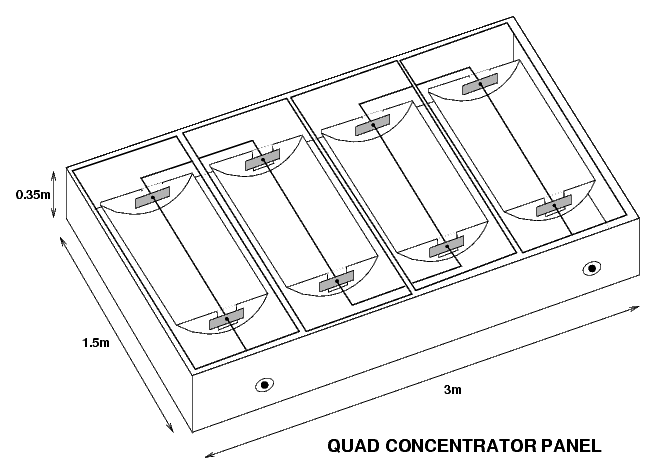
The Quad Concentrator Panel
But the idea of connecting multiple collector panels inside the same sealed panel can also be applied in a different way. In the tests described in my last log I confirmed that my design is much improved when sealed with a transparant cover. Instead of mounting the glass or perspex directly on top of the concentrator trough, which is particularly awkward when using second-hand glass to save cost, a row of separate semi-circular solar concentrators could be mounted within a sealed box with glass panels on a frame on top.
Besides making the mounting of the glass easier, the box would add a second layer of insulation around the solar concentrators and their connecting pipes. Ideally the top edges of the concentrators would have a foam seal that touches against the glass so that there are separate sealed sections inside the concentrators and inside the collector box. Empty spaces in the box would ideally be filled with ceiling insulation material.
A relatively nearby business is currently selling used glass panels in aluminium frames with dimensions 1,500mm x 750mm, for $50 each with 50 in stock (maybe). The concentrator dimensions are 900mm x 580mm, so this suits such a design quite well, with ample room around the ends for interconnecting pipes. Four concentrators, with a glass panel each in the top of the sealed collector box, would be 3m wide. It would be mounted at a 22 degree incline.
I would prefer if the cost of the glass was a little lower, but other sources don't have lots of identical frames the same size. On the upside, it might be safer to use cheaper chrome vinyl wrap for the reflective coating given that in this design it's not exposed to rain. It avoids the problem of the drums rusting as well.
The next step is to work out what materials to use. I'm currently thinking of a wooden frame, with the sides covered by sheets of corflute. 1/2" steel pipes with threaded couplings. I've already found a decent set of old 44 gallon drums.
Well it's been a while but I have still been tinkering when time and less-wintery weather have coincided.
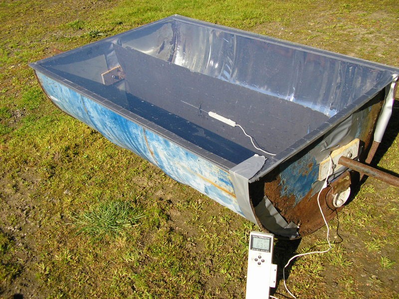
I eventually got myself a decent piece of perspex and sealing the solar concentrator up with that makes a significant improvement. On a clear winter day at an ambient temperature of around 13degC in the shade, the collector temperature got up to 63.5degC (50.5degC rise). That's definitely the best performance yet.
At that point it was worth comparing all of the configurations that I've come up with so far:
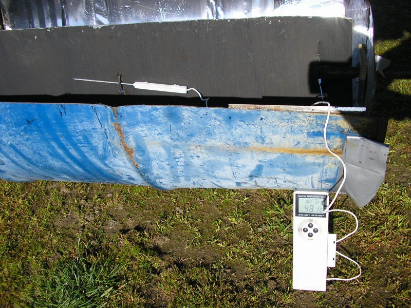
Rectangular collector panel (vertical), no perspex: peak 48.1degC (35.1degC rise)
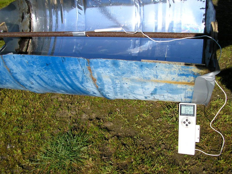
Bare pipe, no perspex: peak 32.8degC (19.8degC rise)
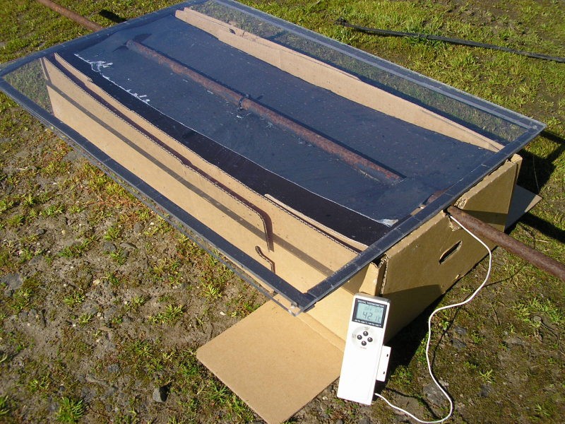
Rectangular collector panel (horizontal) in cardboard box with perspex: 42.1degC (29.1degC rise)
So the latest (and most complex/expensive) arrangement with the rectangular collector panel vertically orientated in the semicircular reflector, all sealed up under a perspex window, is definitely the best by a good margin. It also protects the chrome vinyl wrap.
These tests are pictured below. All four tests were conducted within the space of an hour under clear sky.
But the cost of the perspex is a but prohibitive for making lots of these. New sheets are over $100 for sure and it isn't the sort of thing that seems easy to find used. Glass may be easier to find cheaply, but more difficult to work with.
Even lots of used glass can be tricky to find, but I did find someone selling solar collectors from an old home solar hot-water system made in 2011. So for $75 I picked them up and if nothing else it might be educational to pull one apart, as well as to try comparing performance once I move to actually trying to heat water. Unfortunately they aren't the sort with the evacuated tubes, though those never seem to be a length that suits the height of these steel drums anyway.
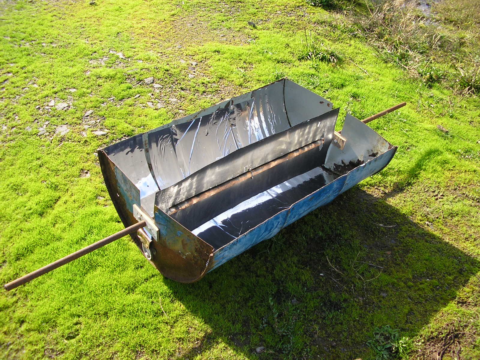
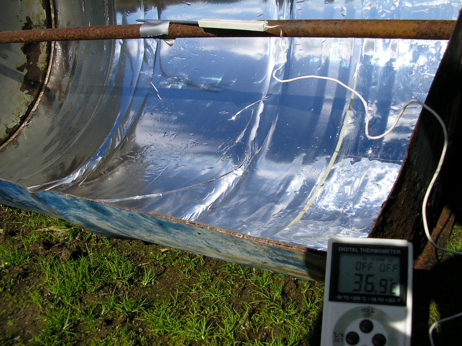
I finally caught the sun poking out from the clouds last week (I'm getting a bit slow with these updates) and got the chance to test the new collector panel. The increased surface area 'collecting' both direct and reflected light is obvious.
From an ambient temp. of 13degC in the shade, the collector peaked at 32.5degC (19degC rise) which is... not as good as just the pipe on its own. Clearly the heat dissipation to air is too great, even with the illuminated area far greater than with just the pipe on its own. The cold breeze blowing wouldn't have helped either.
I'm not quite ready to give up on the black-rectangle collector approach yet though. Sealing everything up by putting a piece of clear perspex (polycarbonate) over the top should prevent air circulation and therefore reduce the heatsinking effect. This is suggested in some regular parabolic solar concentrator designs anyway. The perspex will absorb some light as well, and looking at websites of distributors and DIY PV solar panel constructors suggests roughly 90% transmission of light through thin perspex. Glass would be a little better, and wouldn't discolour over time, but for testing perspex will be much easier to work with and close enough to get an idea of whether it will be worthwhile.
Of course I could still switch to what everyone else does and use a parabolic reflector, but the temptation of easier manufacture and no need for a solar-tracking system still draws me to this design.
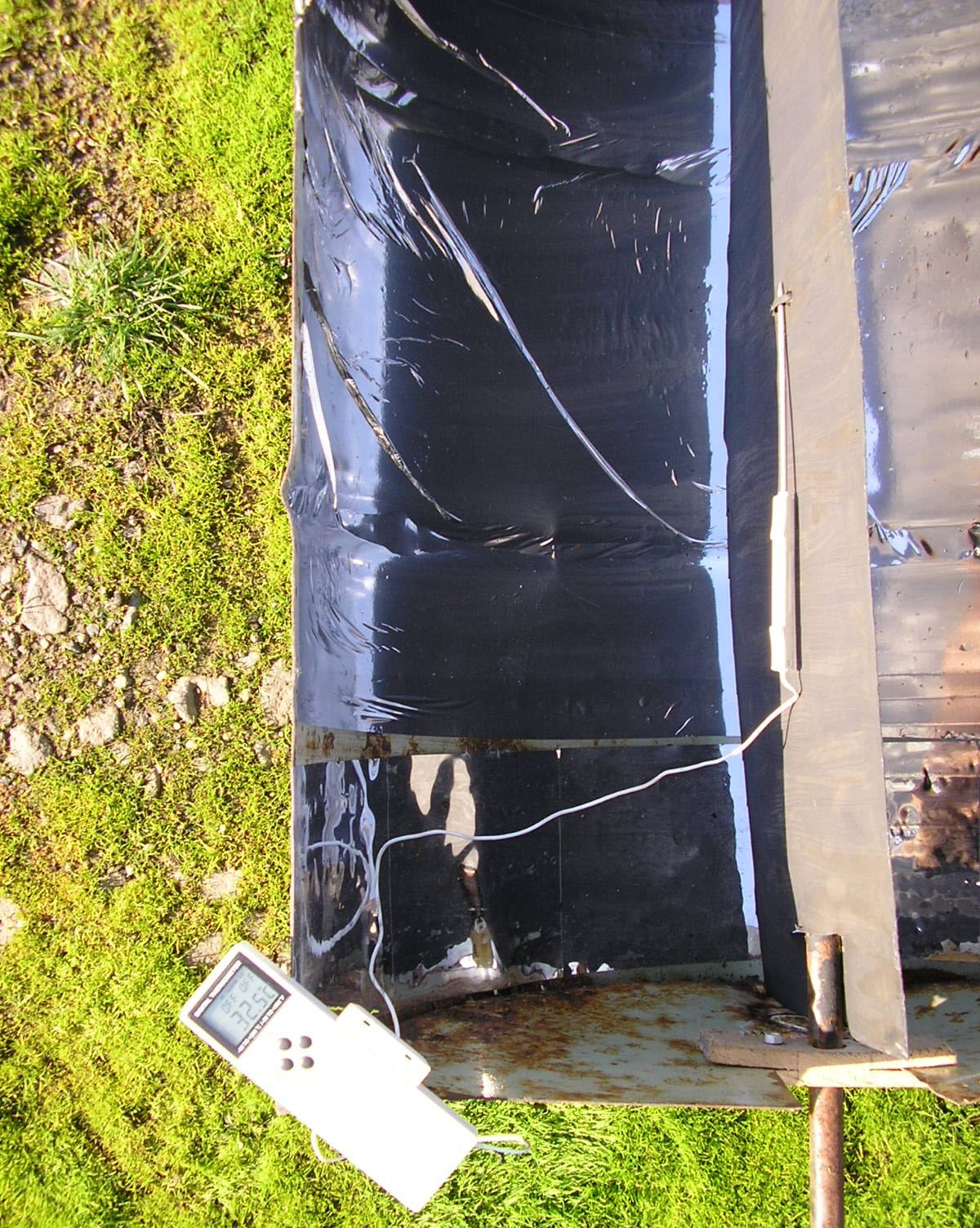
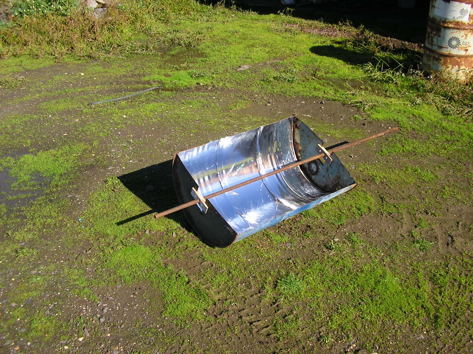
Well It's too late for the HackADay prize, but I finally had a go at applying a sheet of Chrome vinyl wrap as an alternative to the disappointingly crinkly self-adhesive mirror sheets. The mirror sheets were left on at one end for comparison.
I did a pretty rubbish job with my first wrap attempt, wrinkles and air bubbles everywhere, but for this it doesn't really matter. Where it went on properly it conforms to the drum surface far better than the mirror sheets, which is the main thing. Although it's also self-adhesive, the instructions say to use a heat gun to set the adhesive (I presume), so I borrowed one and used it at the 250degC setting. Note that the wrap shrinks a bit when the heat is applied.
The sun was out, but being late autumn (in (southern) Australia) it didn't have that much bite. Still, the aim is naturally for this to be usable year-round. As shown in the below image a peak temperature with the concentrator pointed at the sun was 37degC. Ambient temperature measured with the same thermometer in the shade was around 16degC, so there was enough heat for a 21degC rise in the temperature of the pipe. Note that the excess length of the pipe beyond the concentrator acts as a heat-sink and probably reduces the achievable maximum. For the purpose of boiling water though, it was hoped that a greater rise would be observed, though connecting multiple concentrators together in a line should increase the temperature.
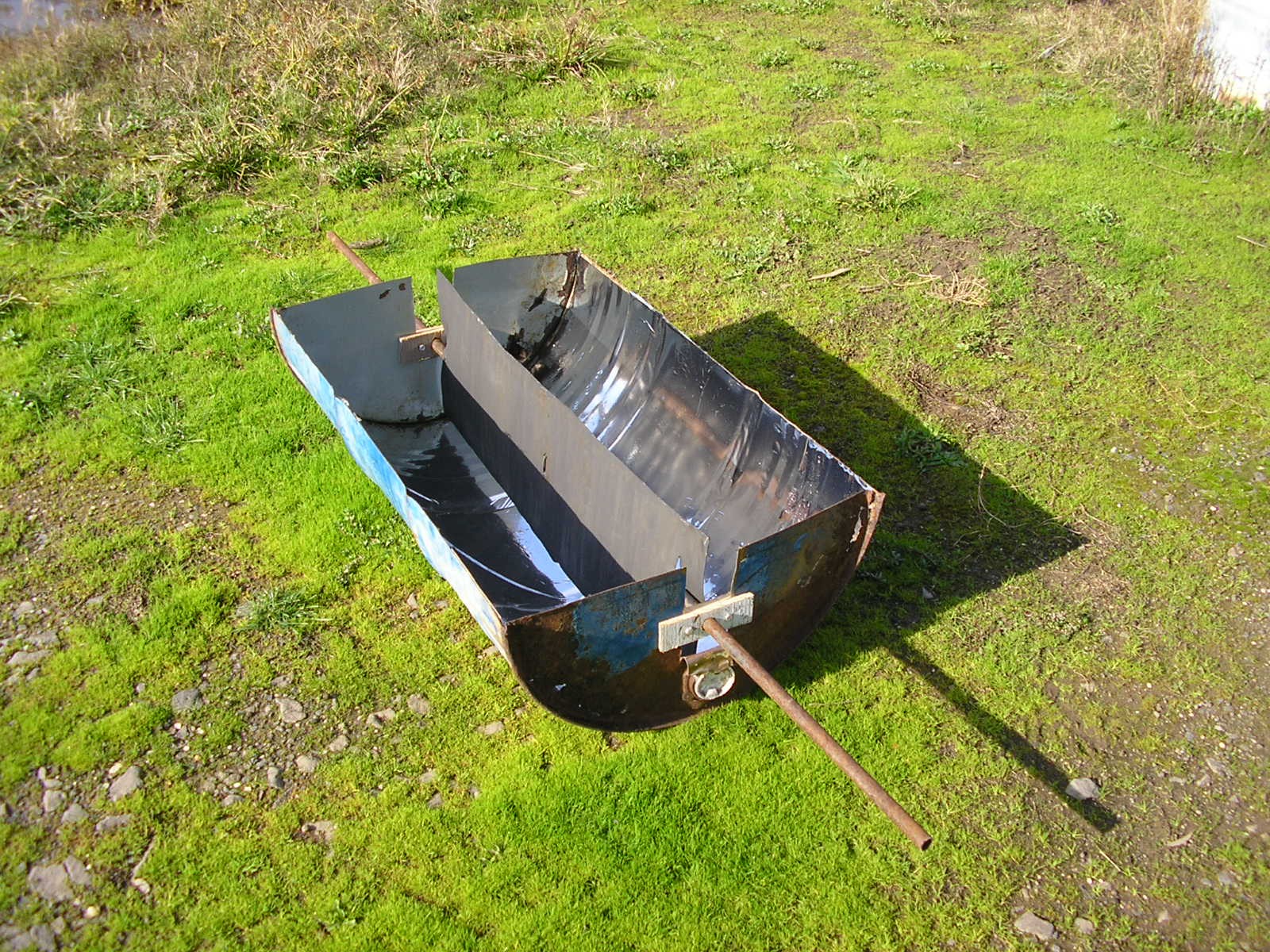
The paper on semi-circular non-tracking solar concentrators describes a vertically-positioned collector surface which is as tall as the radius of the semi-circular reflector. To see how this might improve upon the above measurements with the bare pipe, a rectangular section of galvanised sheet metal was cut out and slits were cut, through which the pipe was threaded. The result is shown in the below image. Though increasing the collection area and theoretically avoiding the need for tracking, this larger surface area will inevitably also act as a heat-sink dissipating the collected heat away from the pipe and into the air. Unfortunately by this point in the day it had become quite overcast so it couldn't be tested.
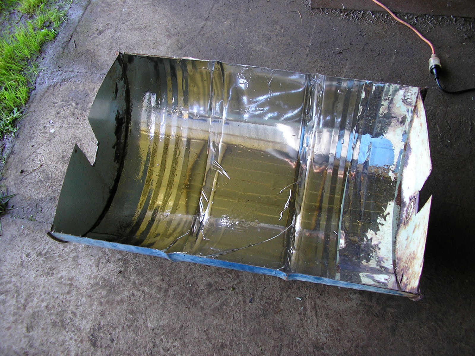
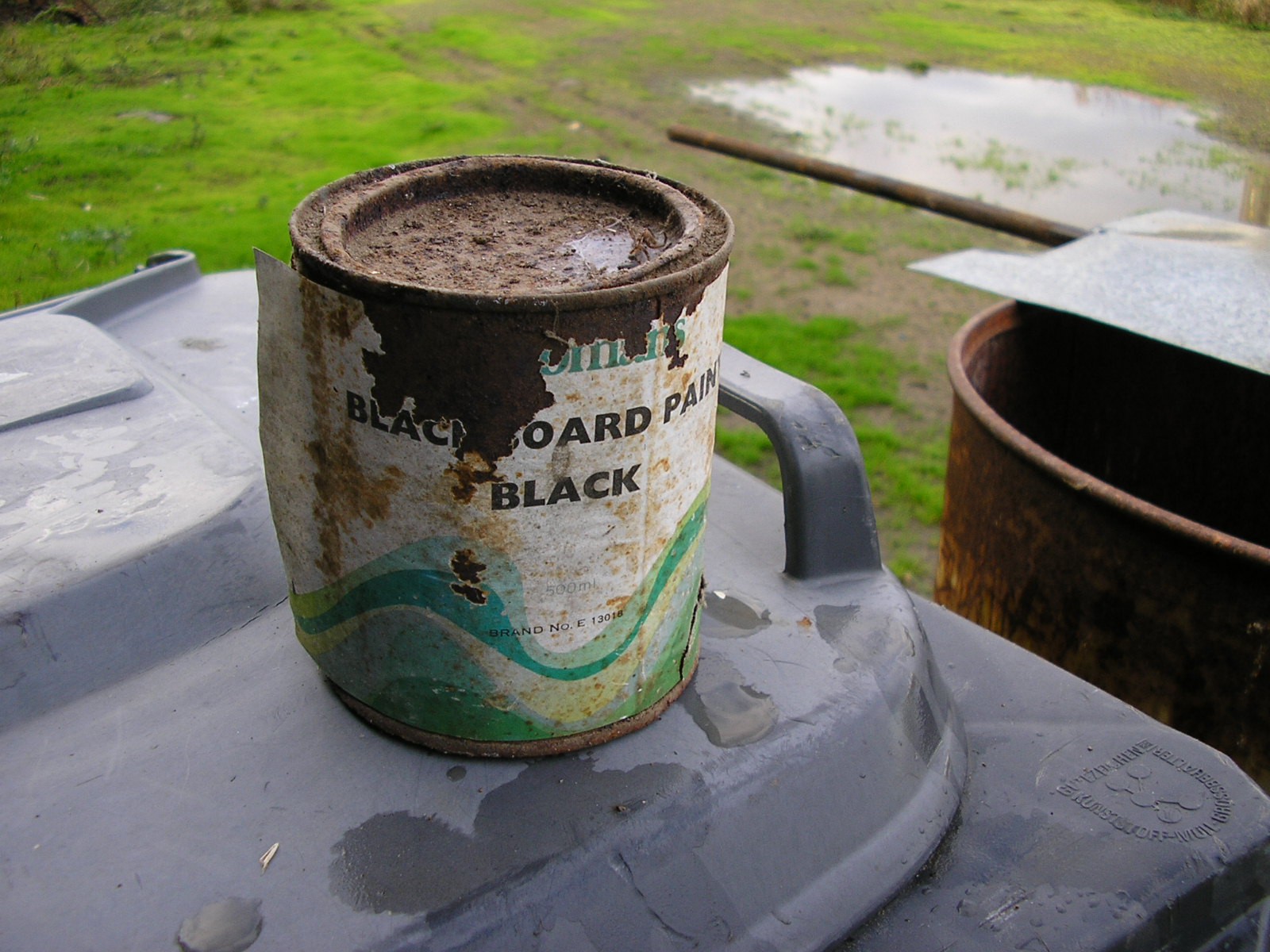
The new rectangular collector surface was quite reflective, so a search for some dark matt paint turned up this rather ancient tin of blackboard paint. This is designed for application on wood, but seemed good for a test because after all what's more matt black than a blackboard?
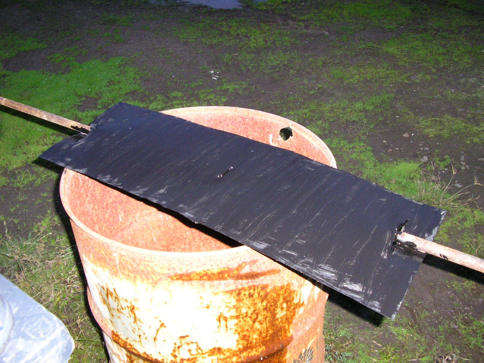
The paint wen't on alright, though after drying there was some cracking, which isn't surprising. Here it is left to dry overnight:
Unfortunately the winter weather set in early this year and there really hasn't been much break in heavy cloud and rain over the days since I finished that on Saturday. In practice of course it needs to work over winter too, but with weather like this that is looking like a bit of a stretch.
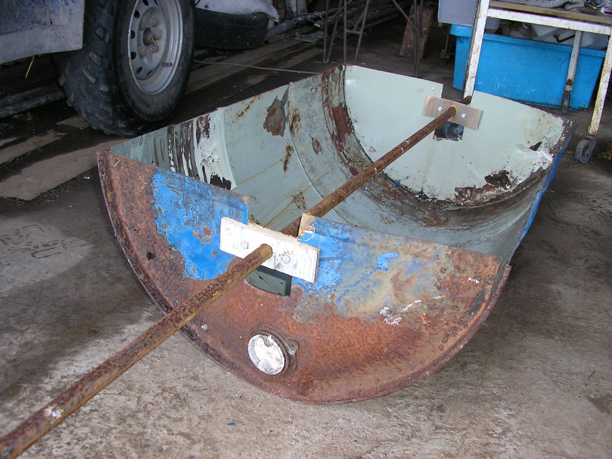
Here's my first solar concentrator build. The aim for now is just to stick a thermometer in the pipe and get an idea of what sort of temperatures can be achieved 'dry'.
The main problem is that the self-adhesive mirror sheets won't work for the mirror surface, they crinkle too much which reflects the light all over the place. I'll try mirror-chrome vinyl wrap sheets instead. I might have to deal with the rust to make that stuff stick though.
Otherwise it came together alright. The design is intended to be simple and cheap to construct. The pipe is secured as pictured in a wooden mount for insulation from the steel. This mount has slits cut into it so that it can be slid to the optimal position, then secured using bolts that clamp the slit shut. This seems to work quite well.
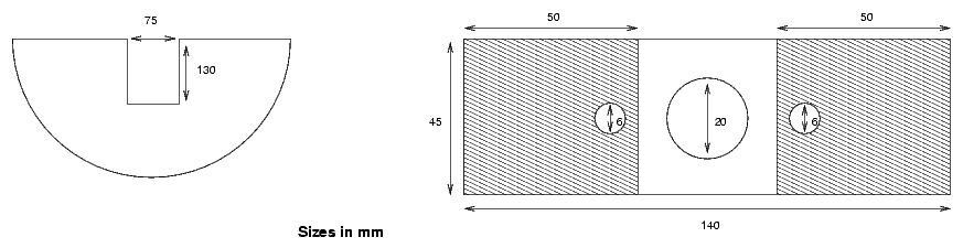
The design for the pipe mounts is shown here, made from an 18mm thick plank of pine:
The shaded sections show the gaps cut through the sides of the mount.
The entire construction process should be documented step-by-step later once the design has been finalised. For now, some basic notes:
The sides of the drum were cut using a jigsaw, avoiding the steel rings at the ends. This worked OK, but wore through two jigsaw blades. A cheaper alternative might be using a drill-powered nibbler tool.
The end rings were cut in-line with the slits in the sides using an angle grinder, so that the drum now parted in two.
The gaps/slots in the end plates for the pipe mounts were cut using tin snips.
The mount pieces were cut from a plank of pine, taking care that there were no splits or knots in the timber. The 6mm bolt holes were drilled, then the slits in the ends were cut using a hand saw. Exact straightness wasn't necessary for the slits. The hole for the pipe was drilled using a forstner bit, and widened slightly with a round file until the pipe fit through snugly.
The end pieces were slid individually into the gap cut out in the ends of the drum, and the pipe was then inserted through them. The friction without the bolts is enough to hold the pipe in position for testing, but their addition and tightening locks the mounts in place much more securely.
Reflector Shape
An optimal design, such as others documented online would use a parabolic reflector. It may be possible to form a parabolic shape from an oil drum by cutting out a section of the side and both the end walls, then bending the hard circular rims at the ends into a parabolic shape. This may be tested later, but it's hoped that the semi-circular trough will be good enough that the ease of construction overcomes the sub-optimal optical characteristics. Basically, quantity over quality, so that losses in the optics are overcome by easier construction of the semi-circular concentrators, allowing more to be produced to compensate. Plus you get two semi-circular concentrators per drum, instead of one parabolic one (maybe).
It may also be worth investigating using a vertical absorber plate rather than just the pipe alone. This paper suggests that a semi-circular solar concentrator can in fact be more efficient than a parabolic reflector in this configuration, and without the necessity for solar tracking.
Pipe
Also known as the 'receiver tube'.
Size for the moment is mainly a guess, with other designs online using a variety of different diameters, usually while quoting some maths that I don't really comprehend. I'm expecting to rely on experimentation to work out exactly what's right for this. Obviously for the final design the expected steam pressure will necessitate a certain minimum pipe thickness so that there is sufficient strength.
Another big consideration is whether to use evacuated tubes. These are specially designed glass tubes with smaller solar collector pipes running inside, and a vacuum in the gap between. The vacuum prevents heat loss to the air. These are made for solar hot water heaters and available individually, but unsurprisingly they're expensive. As solar hot water systems are quite common in Australia, it may be possible to get hold of some cheaply that have been removed from an old rusted-out system. Obviously the design would be cheaper/easier to replicate if they weren't required though.
This webpage demonstrates super-heated steam generation with solar concentrators using evacuated tubes.
The pipe may be painted matt black to maximise absorption. Perhaps look at paint for car brake components as this is designed for high temperatures?
Mirror Coatings
This is the most immediate thing to sort out because as mentioned the self-adhesive mirror sheets don't seem suited even for testing.
Chrome vinyl wraps supposably provide a mirror finish, and are designed to be attached smoothly to curved sheet-metal surfaces. They are also supposed to be weather-proof, though looking around online it seems six months might be the likely lifespan outdoors - perhaps extendable by painting over the top with clear coat spray paint?
Chrome spray paints are available which contain chrome-plated metal particles, but apparently it's not possible to achieve a mirror finish with these.
Actual spray-on chrome plating kits are also available, but very expensive.
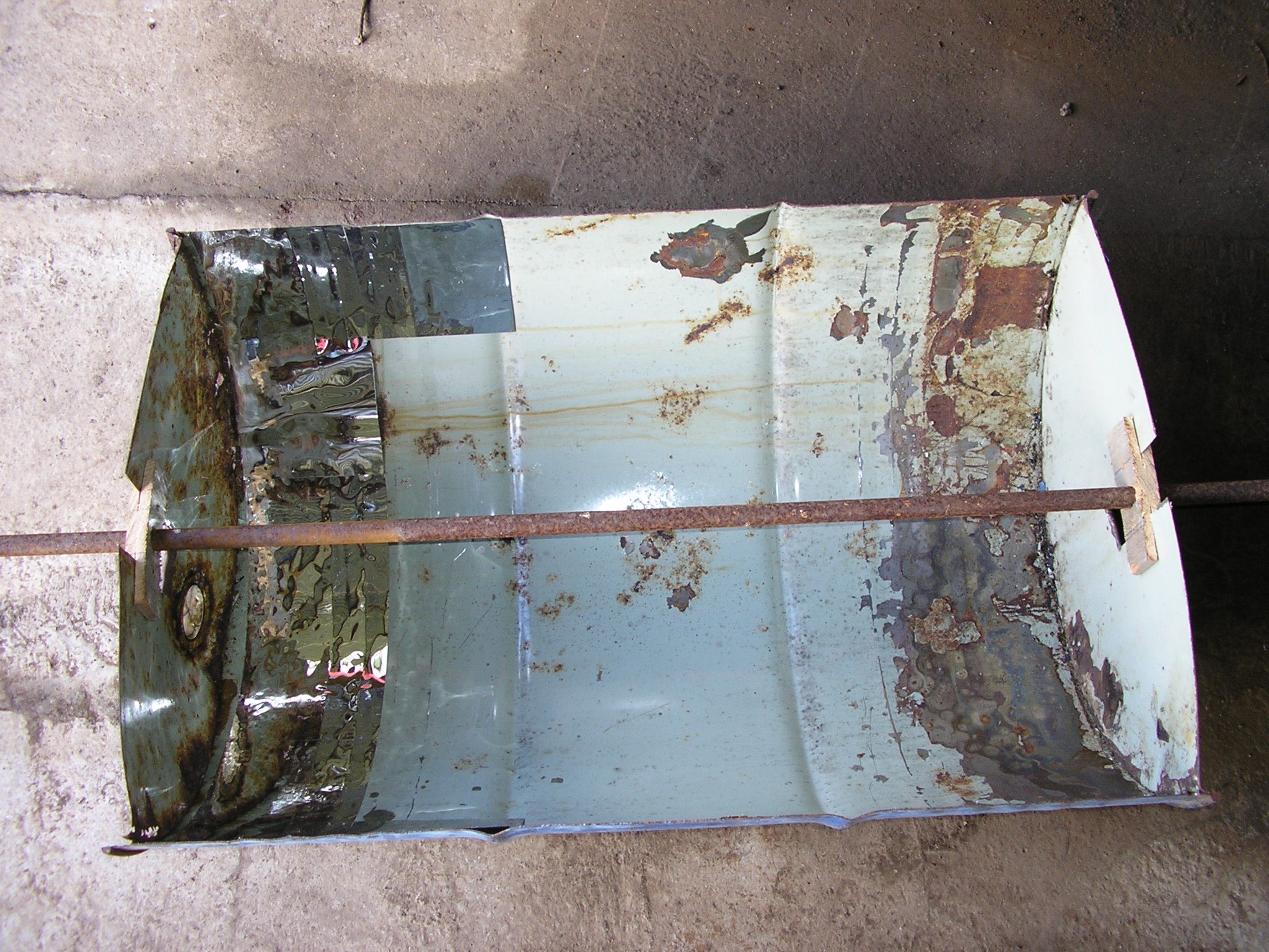
Finally, the drums themselves actually have a reflective surface inside, though I was disappointed to see that this had been painted over in the drum that I used (though still visible where the paint has flaked away). This doesn't look to be reflective enough though.
Drum
The one I used had a few dents, which not only mess up the angle of reflection from the mirror surface, but also make for points where rust starts.
The paint on these is very poor, after all they're designed to be just single-use. Besides clear-coat over the mirror interior, the outside will need to be painted as well. Removing the old paint might be done with paint stripper, or using a sand blaster which would remove rust as well. What about the energy storage bit?
I'm still reading up on all the physics around that at the moment. The solar concentrator will be needed in any case so it's worth making a start on that first. Plus a simpler and cheaper solar concentrator design is worthwhile in itself, even if it's just for the usual stuff like heating water or cooking lunch.
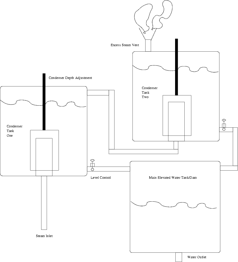
This idea has been rattling around in my head for a long time, but in the specific form of connecting a solar trough steam generator to an elevated tank or dam via insulated steam pipes, condensing the steam, and then piping the water back down to a hydroelectric generator driven by the pressure of the water under gravity. The water in the elevated tank or dam therefore amounts to stored energy to power the generator overnight, and excess steam pressure during the day could optionally be used to power another steam turbine generator.
A sequence of condenser tanks was envisioned as depicted in this diagram:
So upon hearing that the HackADay prize featured a suitable category, I decided to finally have a go at realising my solar-hydro dream. I'd long considered using second-hand steel drums (for oil, etc.) cut in half as the trough reflectors, simplifying construction as well as reducing cost. So I got to work with a jigsaw and angle grinder tearing one of the old ones sitting outside my house into two. This all went well enough - it turns out there was even a reflective surface inside, underneath a poorly adhered layer of paint, though not quite reflective enough. However by now I'd got thinking about the other half of my design, the elevated storage, so I went inside and did some research.
After running some sums described at this website I realised some unfortunate truths. Basically the water needs to be well over 100m above the generator for the pressure to be sufficient that a the volume of water required to produce sufficient energy under gravity approaches something reasonable to store. Maybe it would work with a big tank on top of a mountain, or ideally an extinct volcano with a crater lake at the top already, but for powering my house I was looking at an achievable height difference of about 10m at best. That just ain't gonna work.
So I thought that might be the end of my plans there, but by the next day I'd come up with a full assortment of alternative methods using pressurised water tanks, all based around the core idea: "If steam pressure going in is able to push against an elastic constraint on the storage capacity, then even after steam has condensed, the constraint might still be exerting a force on the water stored".
This in fact relates to technologies known as "gravity storage" or "gravity batteries" (Wikipedia), which seem to be getting a fair bit of recent attention for large-scale schemes. One of the companies has published a surprising amount of technical detail on their page describing their scheme where water is pumped into a chamber dug beneath a massive piston carved out of rock in the ground, so as to lift it up hydraulically, the weight then pushing the water out again later when it is required to drive a hydroelectric generator.
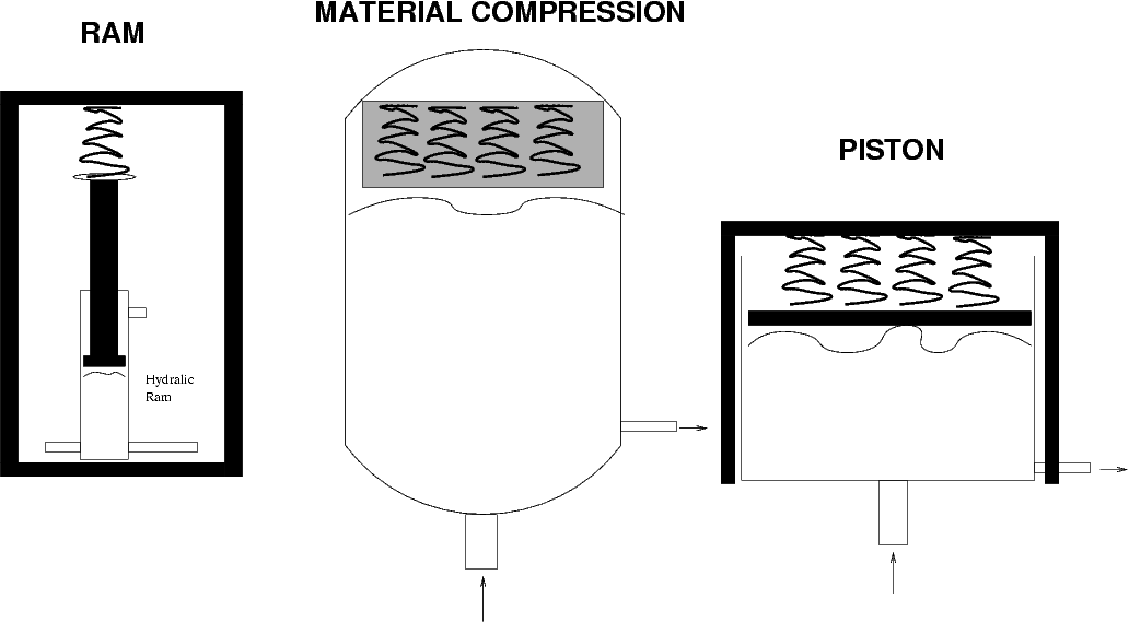
That approach sounds like it might require a few more resources than just my pick and shovel, but these similar concepts are hopefully more practical on a small scale:
Use an old hydraulic ram to lift a weight, with the chamber inside also containing the water (might need many rams in parallel for enough water volume, or just use extremely high water pressure?)
Custom-build a tank and sealed piston, working like a small-scale version of the commercial gravity-storage concept (difficult engineering)
Springs may be worth considering as an alternative to using a heavy weight. Though compressing a spring will be less efficient than lifting a weight due to losses to material deformation and heat, using a weight presents problems with it potentially accelerating quickly to its end-limits if the load/supply conditions change, and risk of it toppling over. The spring approach also suggests another design:
Use an existing pressure chamber (LPG tank?), and inside put a dense non-absorbent foam (query maximum temperature) inside which springs (eg. car suspension coil springs) are threaded through. Steam compresses springs/foam which then presses on the water once the steam has condensed.
These concepts are shown, using springs, in the following diagram:
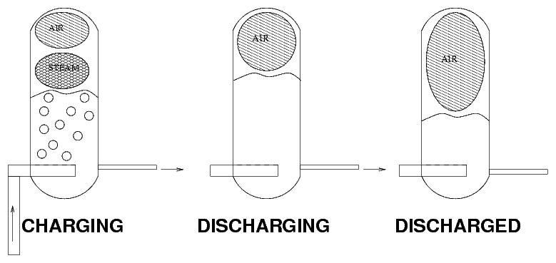
Finally this latter idea can be expanded to simply using the air inside the tank at the beginning as the compressable material. This then becomes a form or Compressed Air Energy Storage (Wikipedia). While this is easiest to build using an existing pressure chamber, it's not clear whether the level of air compression required to store sufficient energy will be maintained after the steam has condensed.
Frankly I don't really know what I'm talking about with this, and like my original elevated storage concept the numbers might not add up for any of these alternative approaches either. So long as I'm still working my way through the details of them one week later though, I figured I might as well publish the project and see how it goes. My immediate intention is to do a lot more research on steam, heat, and pressure vessels. These are naturally a well documented topic from the steam age, and first I think I'll finally make a proper study of my 1942 copy of Steam and Other Engines by John Duncan (the original 1907 edition (my edition shows later revisions) is at the Internet Archive). A quick flip though does much to impress upon me just how little I know about these topics.
Finally, it should be noted that there are existing examples of large-scale solar trough reflector installations being used in combination with energy storage. The Solana Generating Station, completed in Arizona USA in 2013, uses molten salt thermal energy storage (Wikipedia).
Key information to be determined from prototype construction/experimentation:
Applicability of used steel drums to use in constructing solar concentrators.
Shape of solar concentrator trough - half-circle for easier manufacture, or parabola?
Preferred method for increasing the reflectivity inside the solar concentrators.
Weather-proofing methods for the solar concentrators (paint / clear-coat).
Cleaning methods for reflectors in the solar concentrators.
Volume and temperature of steam produced according to the length of the solar concentrator.
Ideal diameter of the pipe running through solar concentrator - in conjunction with the previous dot point.
Necessity for inclusion of evacuated tubes in the solar concentrator design.
Method for maintaining sufficient pressure to force water through the solar concentrator while steam is pressurised on the other side.
Large-scale practicality in both construction and performance of the proposed energy storage solutions.
Other information to be determined through further research:
Required pressure ranges and the implications for construction methods and materials.
Suitability of compressed air for energy storage overnight.
Automatic control systems for hydroelectric generators, to avoid waste of stored water capacity. Possible to use an AC generator while maintaining consistant frequency? Or need to generate DC and use an inverter?
Applicable water wheel/turbine designs.
Eventually, identify the methods available for integrating electricity output from this system with the existing mains electricity connection to my house.