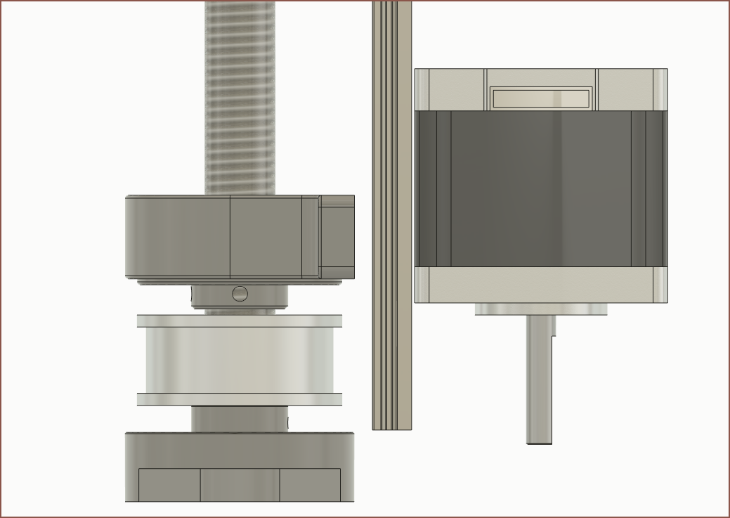
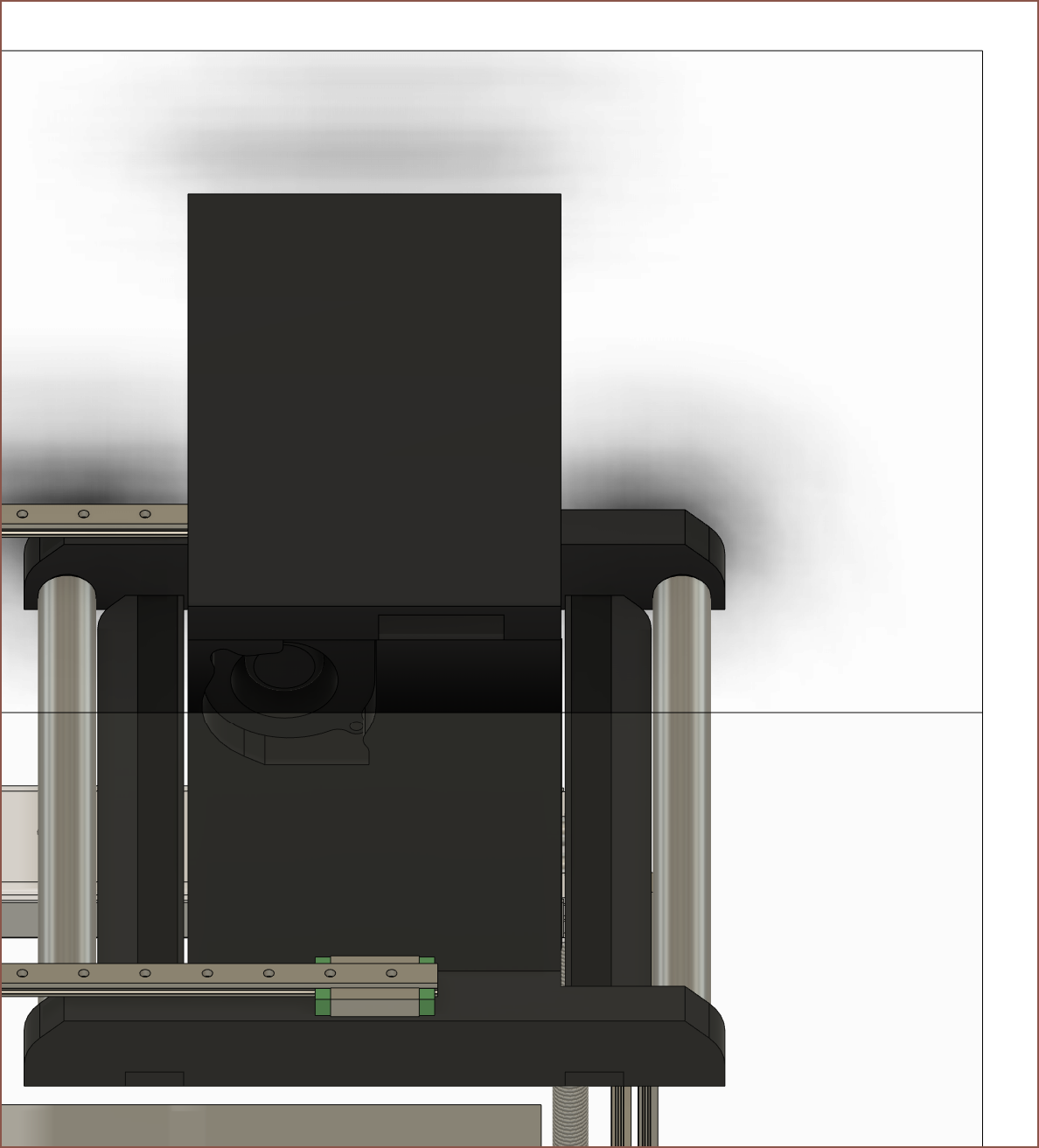
Just done a few small tweaks. Due to the Z rails being slightly short, I left 10mm of Z height on the table. Extending the rails only increased the BOM by maybe £2 or something. The SuspenseSmall is now at a 240mm Z height.

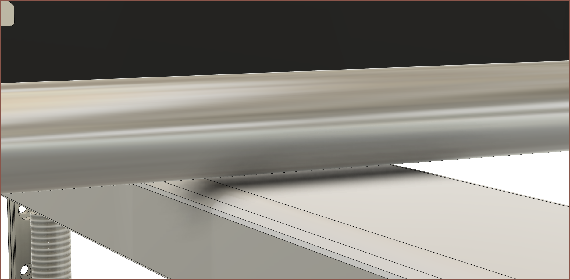
Next, I've added the concept rollers for the X axis. These are cut from the same polished 19mm tube as the roller. So far, the Suspense would need a metal saw (for the aluminium channel) and a tube cutter, which I don't think is that bad. I'm also hoping that I can design the printed parts to fit inside the Ender3 (and various clones).

I've also added a cover to the top of the cleaning roller, which also has a channel for the string. There's not much clearance though, so I'm still wondering about how maintenance is going to work. I just hope that the string is consumed slowly enough to only have to worry about it. I'm thinking of holding the cover with magnets.

Reducing the required controllable motors of the Suspense to 22 has resulted in a notable saving on the BOM. This is under the assumption that a mini servo motor can be used to push the continuous fibre to the fibre arm roller and that the conductive silver paste can also double as solder paste. I can't imagine the second point going well, but I just remembered that I can print a support layer over the PCB that would act as a dissolvable soldermask stencil, though the PnP may not be usable. There's also connecting both Z axis motors to the same stepper driver, a method of using a servo/DC motor for the string puller instead of a stepper or just using a cheap stepper extension board and using 3 spare pins somewhere. Perhaps there's a slow curing silver paste that will allow the PnP to place the components in before it solidifies.

 kelvinA
Discussions
Become a Hackaday.io Member
Create an account to leave a comment. Already have an account? Log In.