 kelvinA
Media
Inspiration and/or examples of working principle
The background music for this one is also the music I mentally associate with this project (though the one in my head is a bit different).
Navigation
Relevant Reading
Contents
The title tag system is explained here, and the most up-to-date is used (so there may be differences compared to the tags actually present in the log's title). Notable logs have bold white text.
Read more »

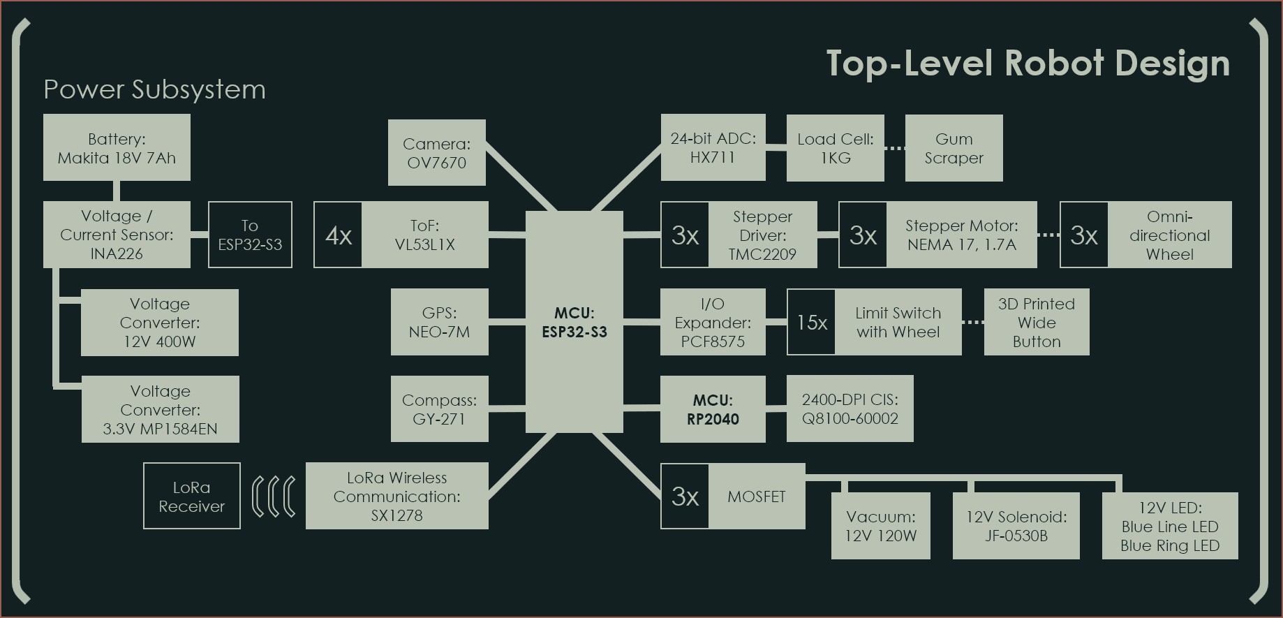

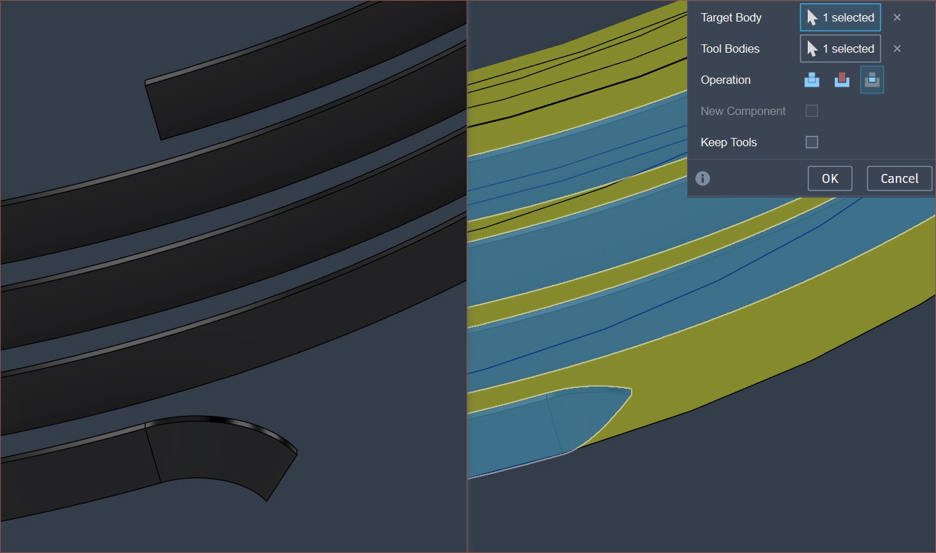
 As any 21st century kid would, I coded this whole thing in one monolith in about 2 hours to then get a lot of "VHDL says no" type errors for another 3 and a half to finally reach the plateau of productivity. Last was polishing everything in another 4 hours. I feel like things would've been even longer if I didn't start programming with easy-to-read variable names:
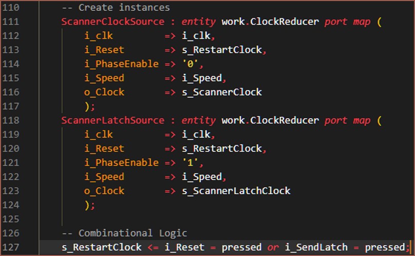
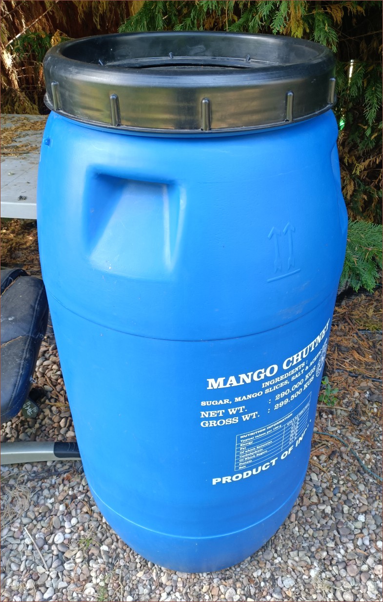


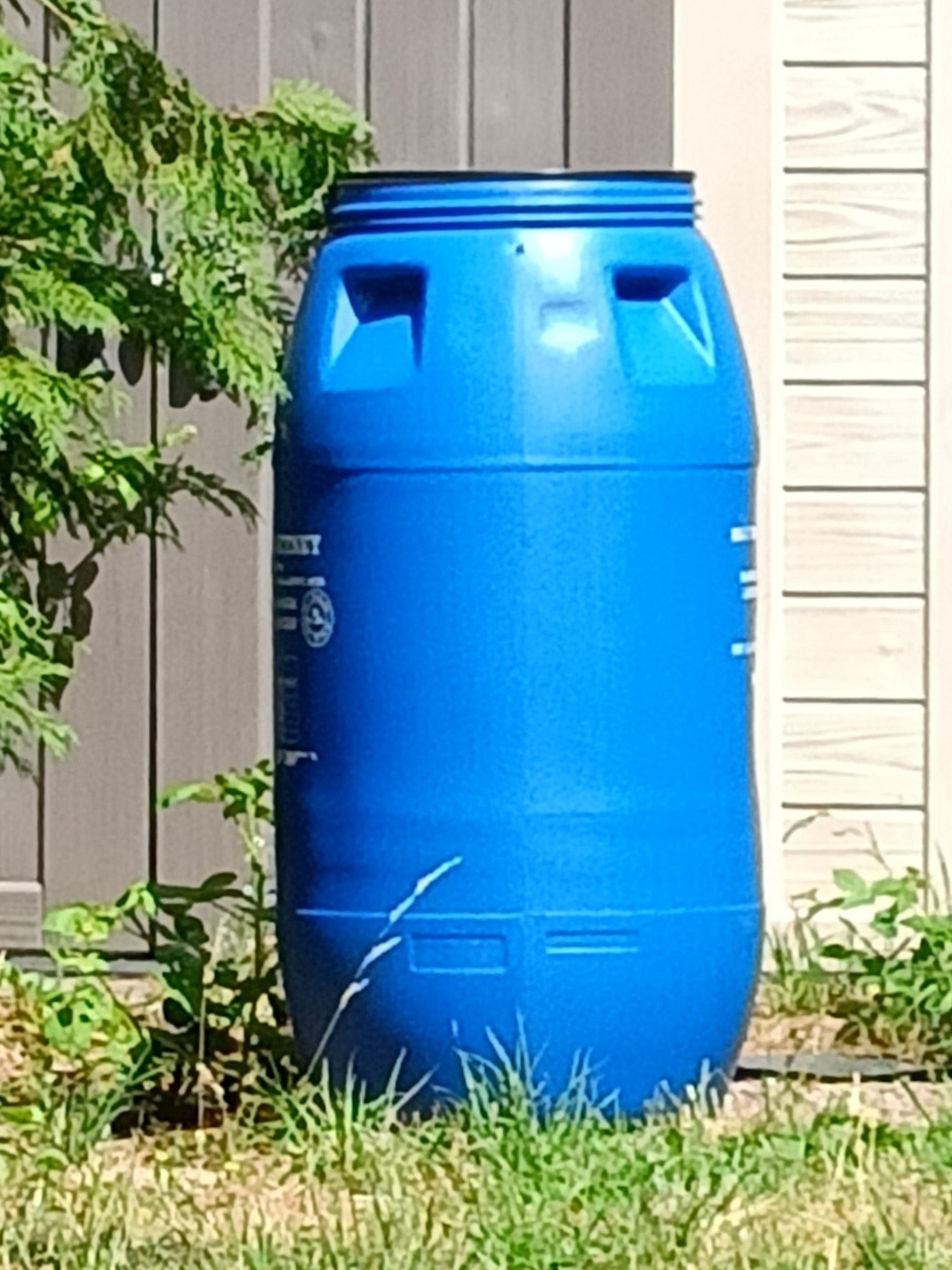
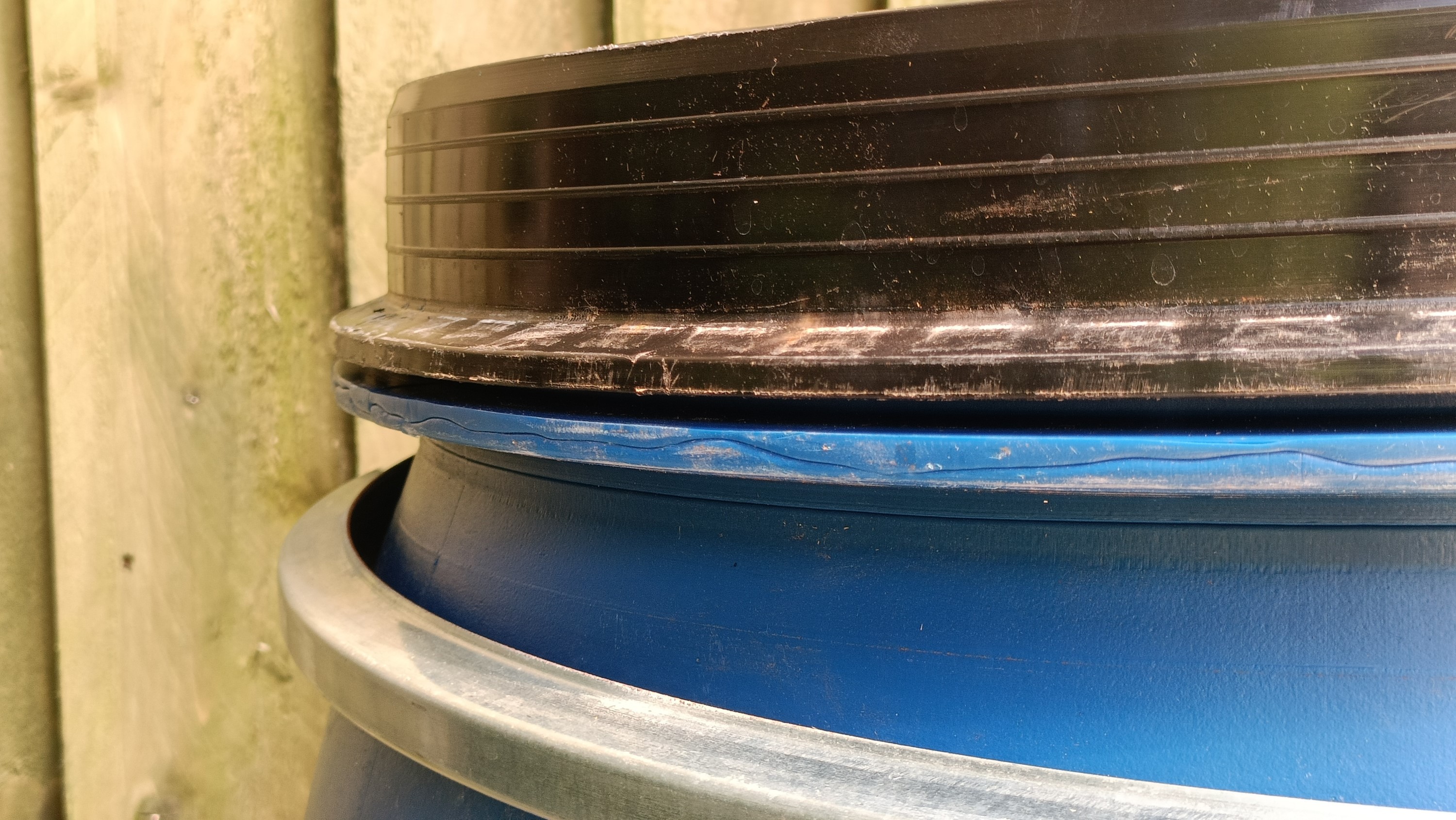
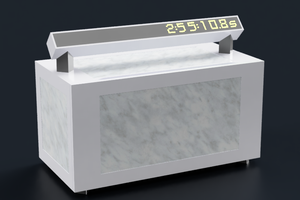
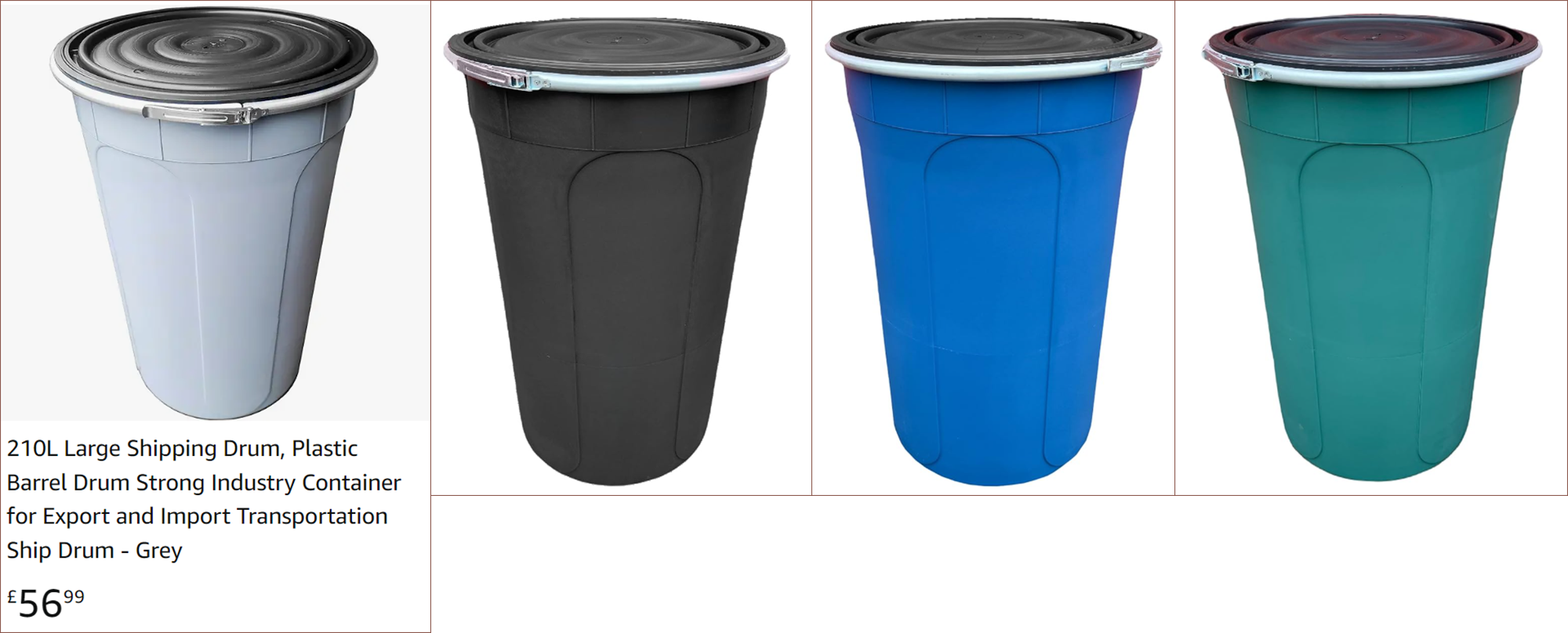 The dimensions are allegedly 500mm on the base, 660mm at the top and 940mm tall. It certainly looks like a more-ideal spread of those litres in terms of fitting components inside, and my opinion is that the light grey does look particularly home-like. Looking at the levels, the light grey is also even more reflective of blue than the blue barrel.
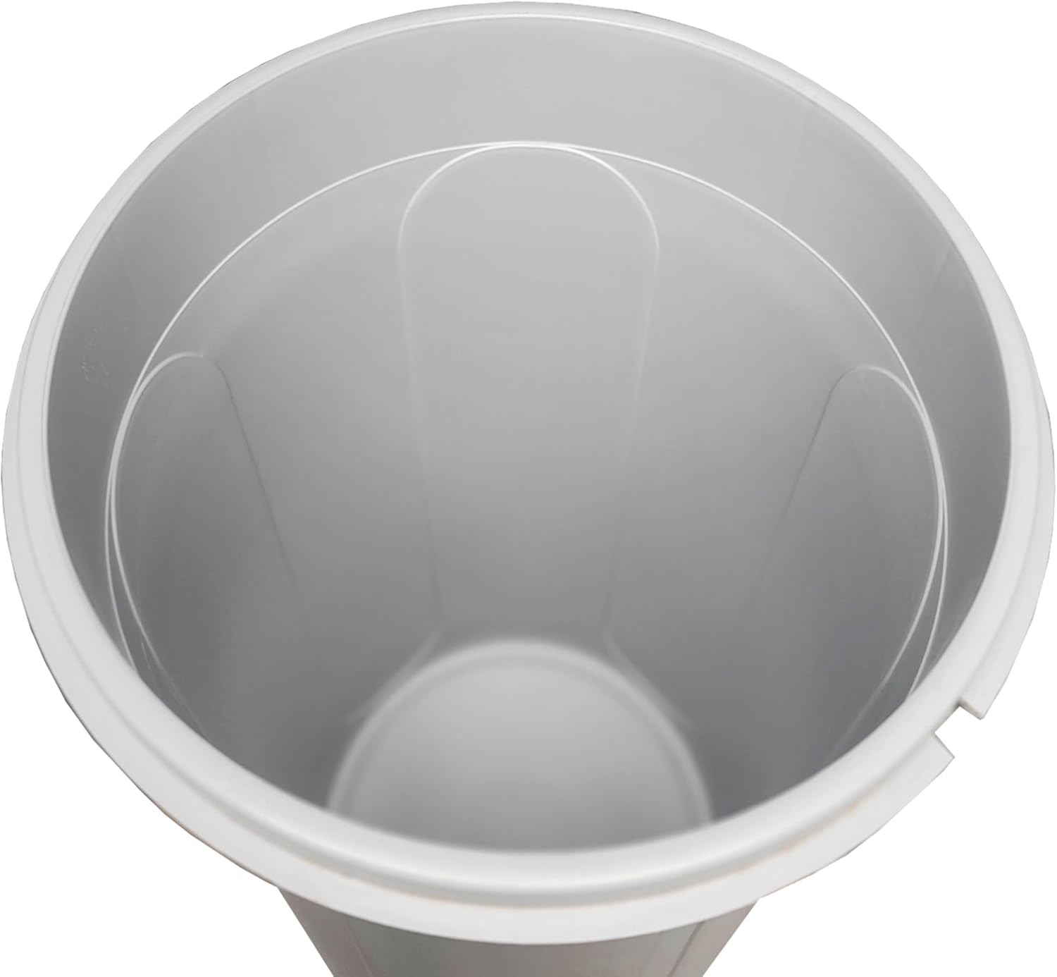

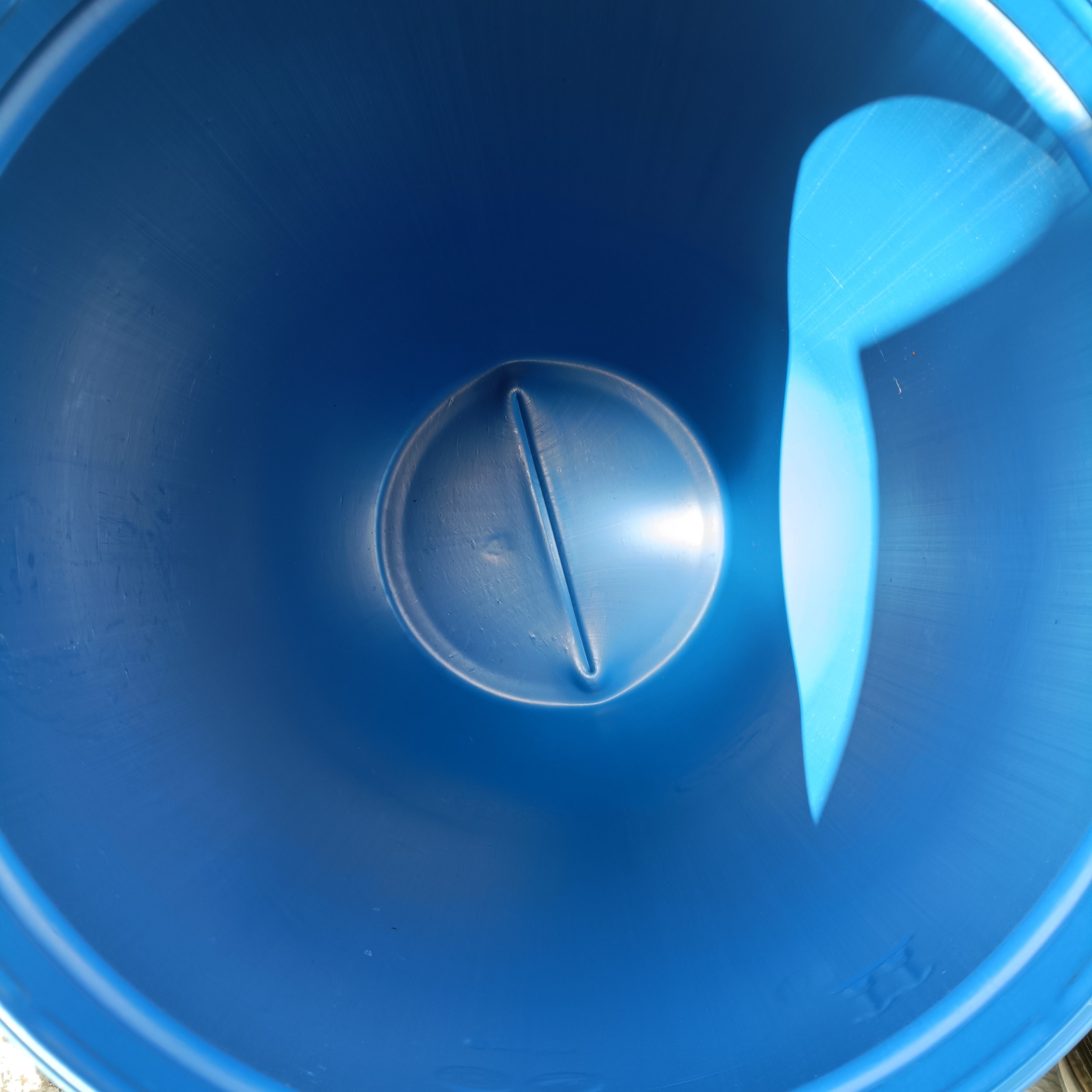
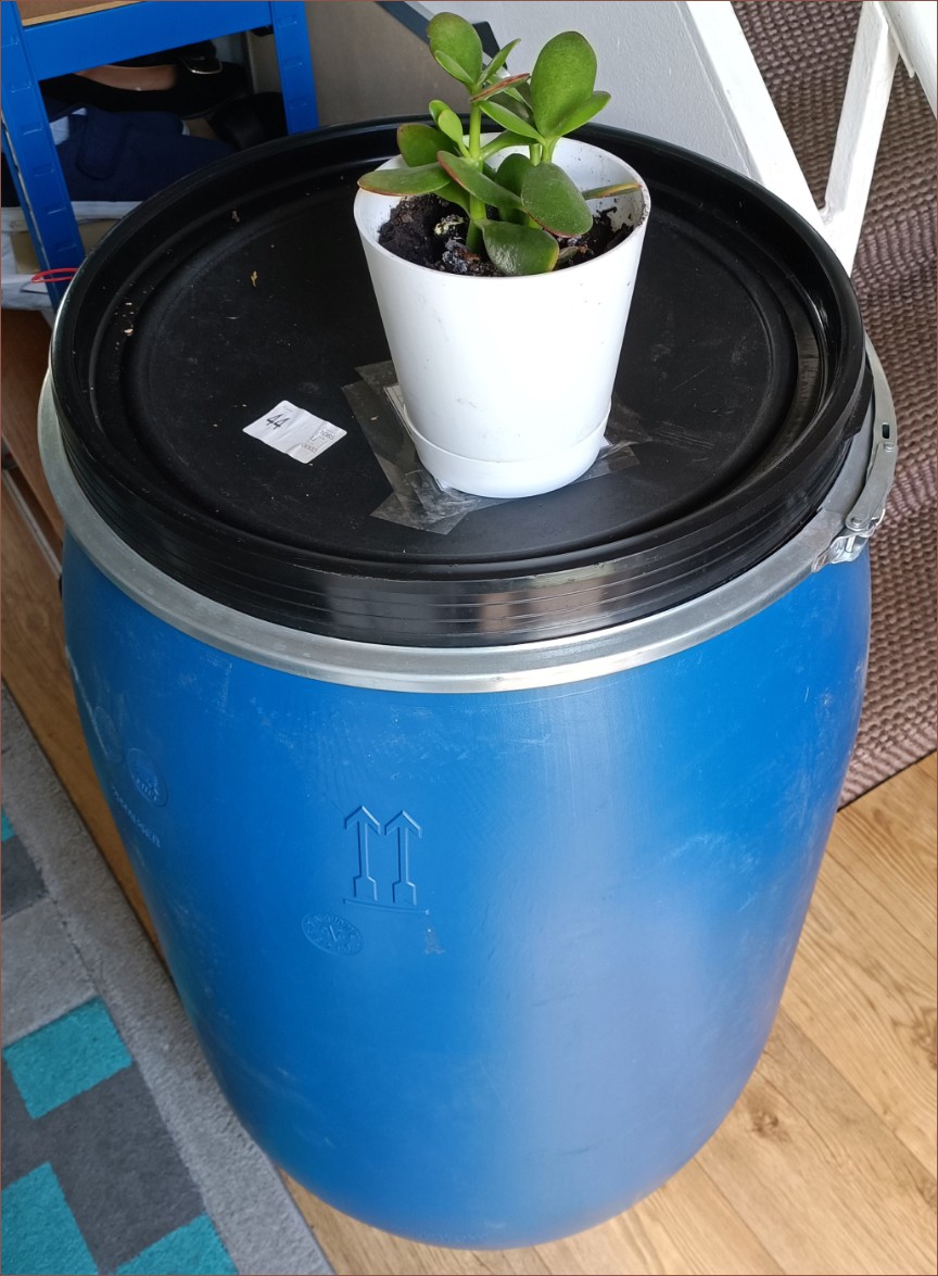

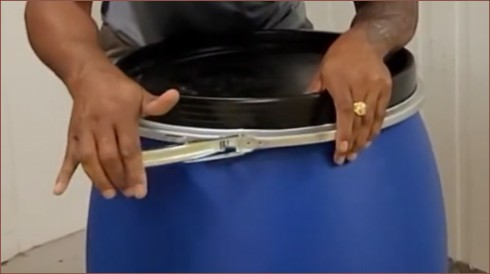
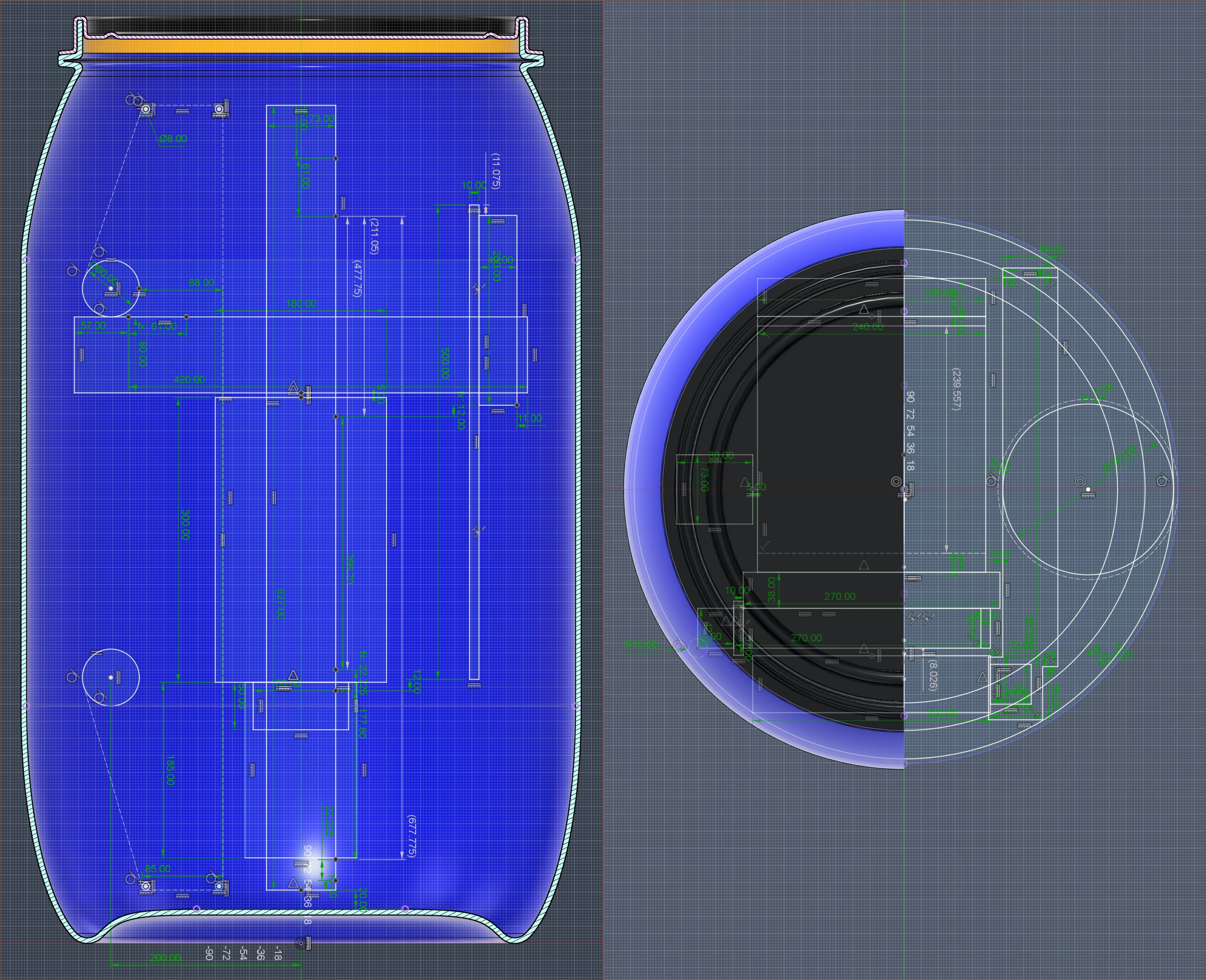
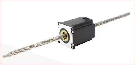
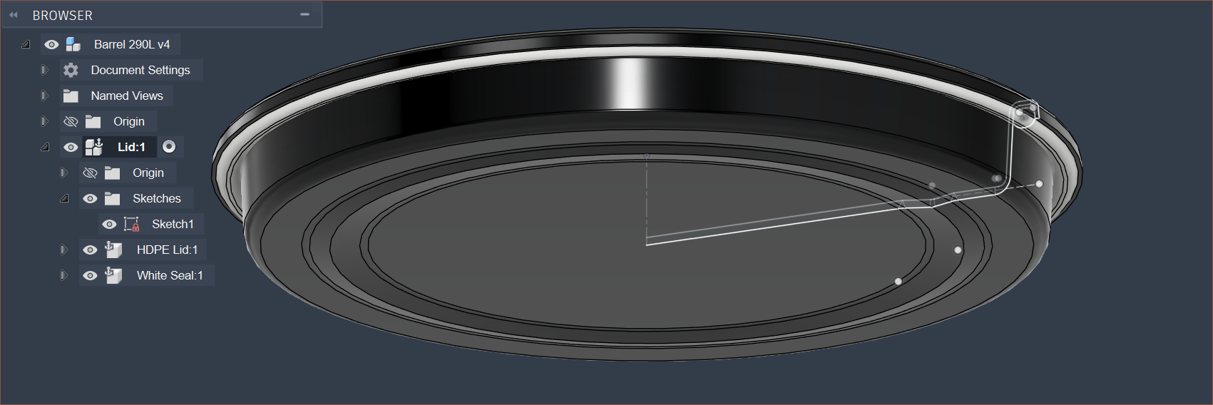
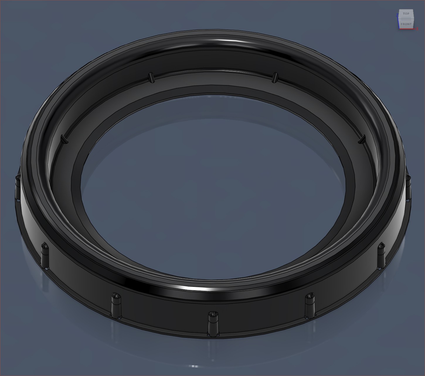
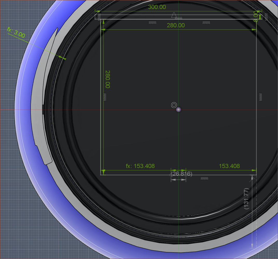
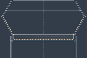
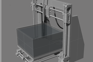
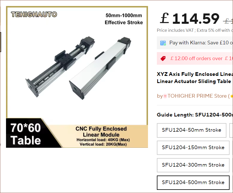 I thought this would be particularly useful for the Z axis. If kept in the orientation seen above, the build plate would be vertical and exhibit no counter-lever sagging, unlike the typical orientation for 3D printers having the build plate parallel with the ground. This was one of many reasons for keeping the barrel upright. However, this orientation risks resin falling onto the ballscrew. Hence, that's why I thought this enclosed module would be beneficial.
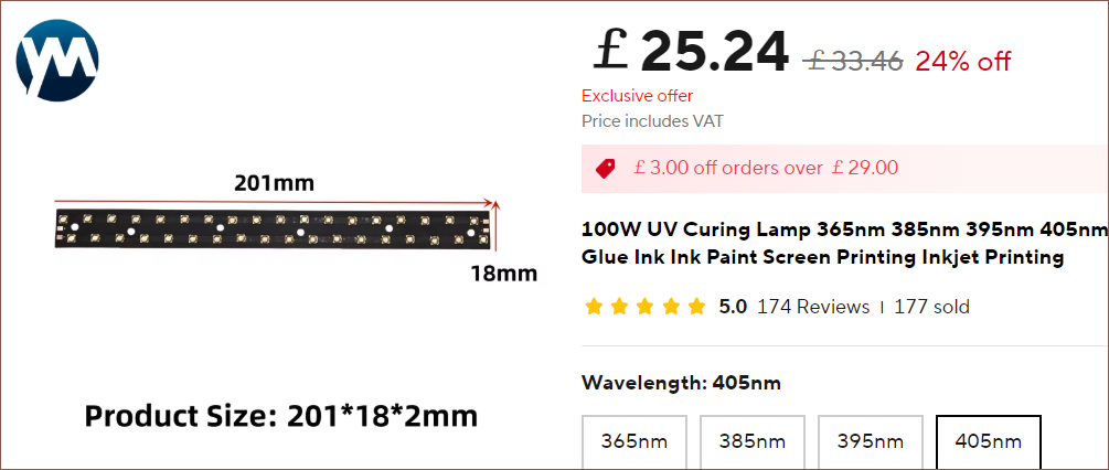
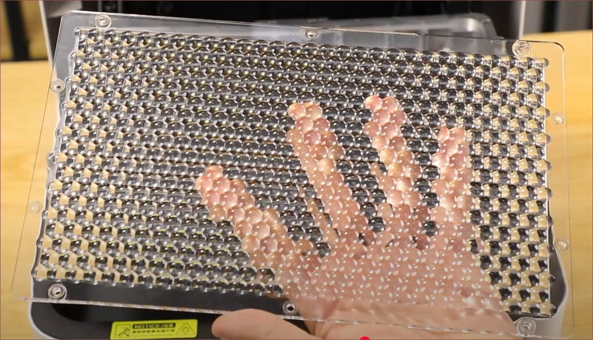
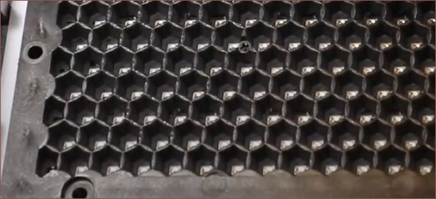
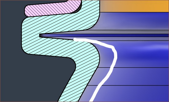
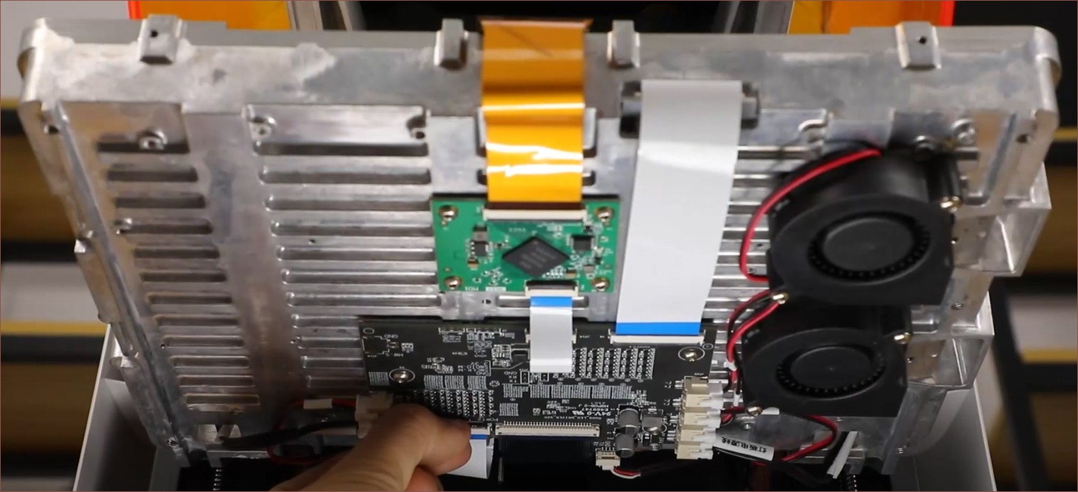 I believe it's also used as a bit of a heatsink as there are fins in it. There are also two blower fans; could they be curving around, or are they to exhaust the warm air? The product page suggests that they use the heat energy to warm up the enclosure.
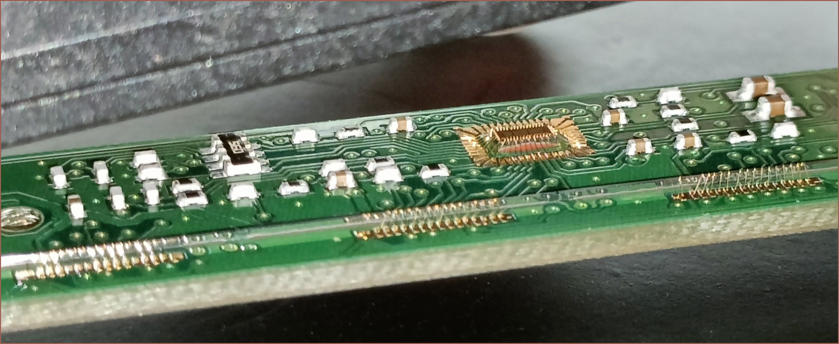
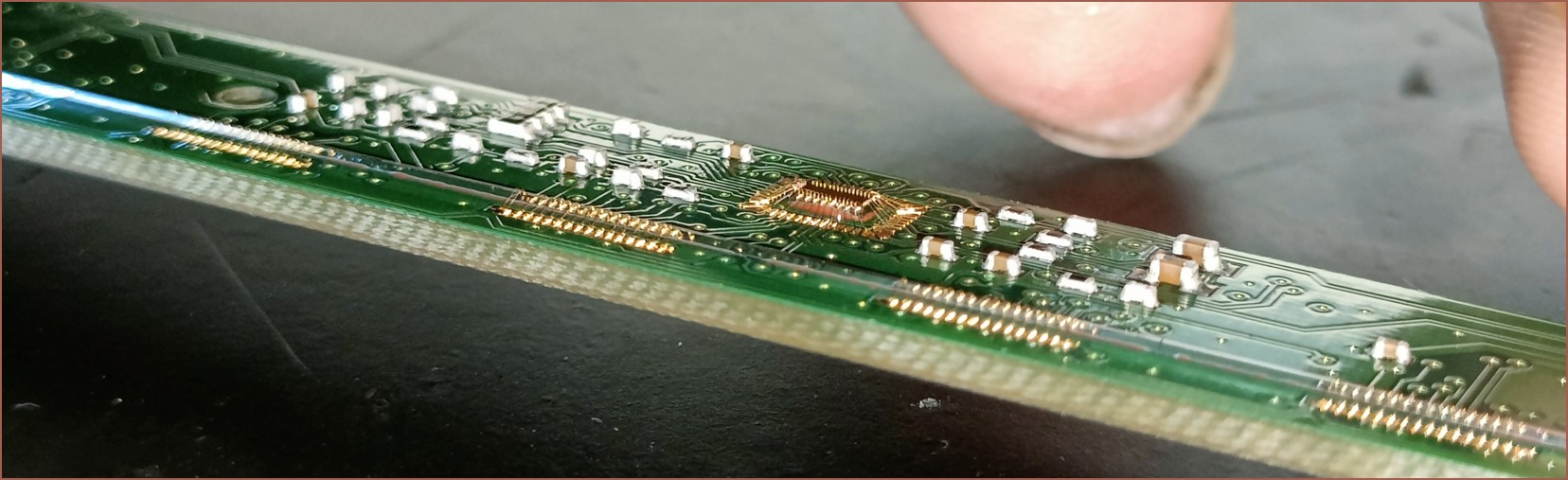
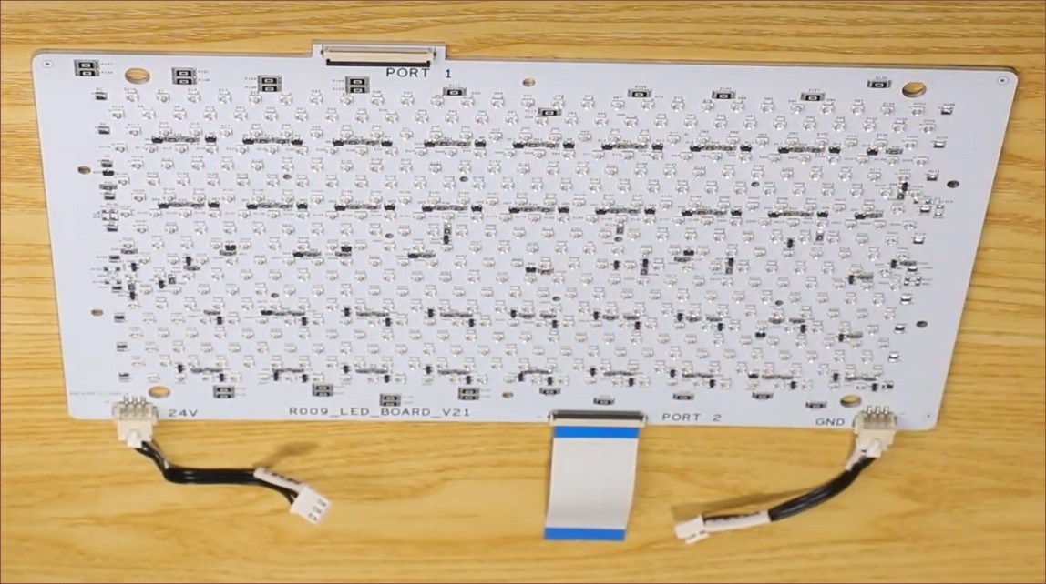 Seems that the LEDs run on 24V and there are 2 ports on opposing sides. Perhaps the electrical path goes through one and out the other? Maybe each port controls half the board? this is an aluminium-backed board, so Creality is likely limited to a single layer, though I do wonder if any of those larger resistors are 0 ohms to jump over tracks. The board is certainly a lot fancier than what I had in mind, which may allude to the reason why it says V21 on the bottom.
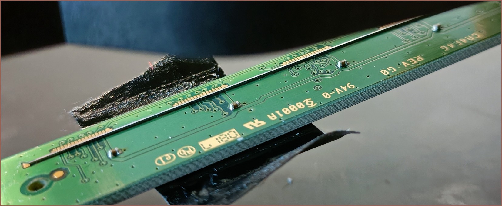
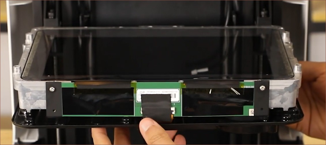
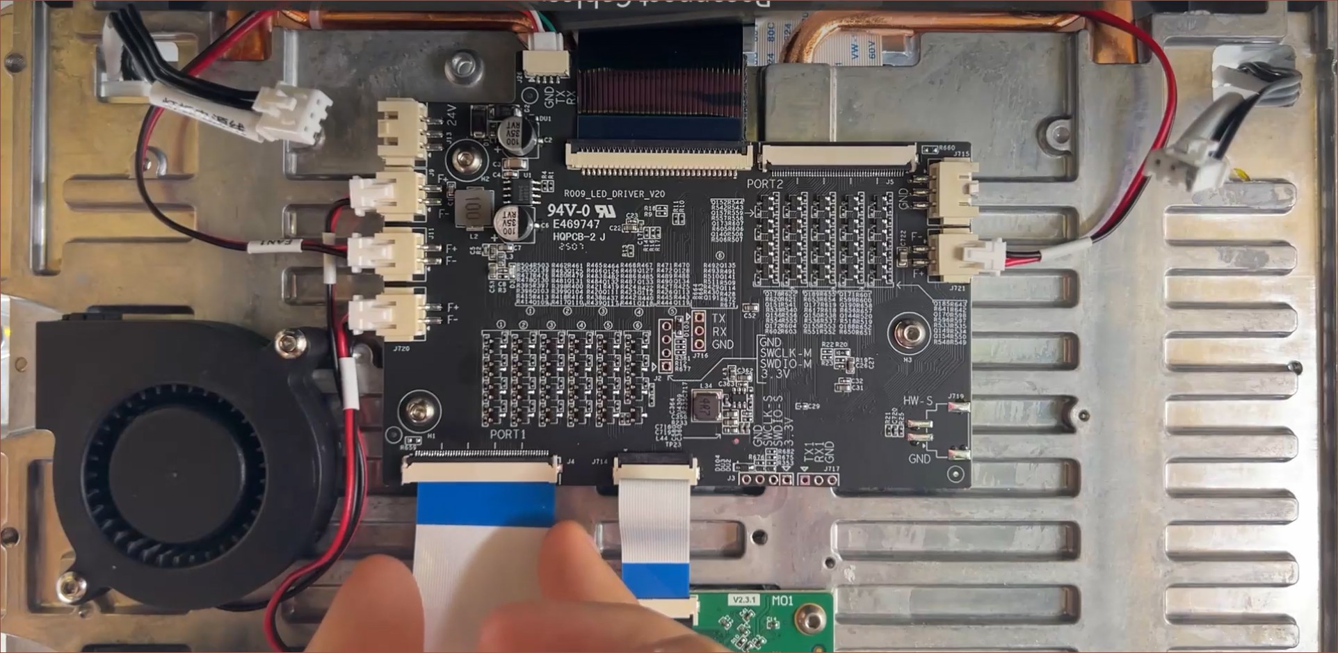 At least this angle allows for a better look at the control panel. The 4 fan ports are obvious, but all the tables are unfortunately a bit more cryptic to me. I think, like with the Q8100-60002 scanner sensor I... still haven't talked about on Hackaday (whoops), the table is just referring to the names of each of the components in the densely packed sections. Is there some kind of regulatory or debug requirement to put each and every component name on the silkscreen? There's also some TX/RX pins; are they for a chip on the other side of the board or exposed from the input ribbon cable?
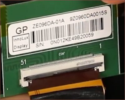 I punched in "ze096da-01a" and one promising result I got was the YI2410A0-1:
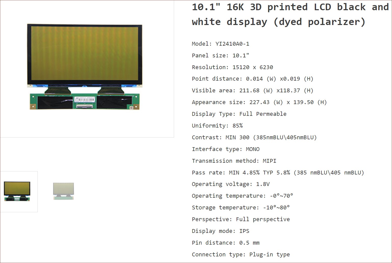 I presume that the dyed polarizer is to further improve LCD longevity?...
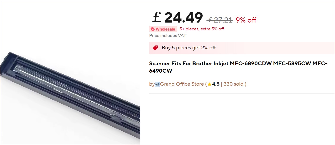

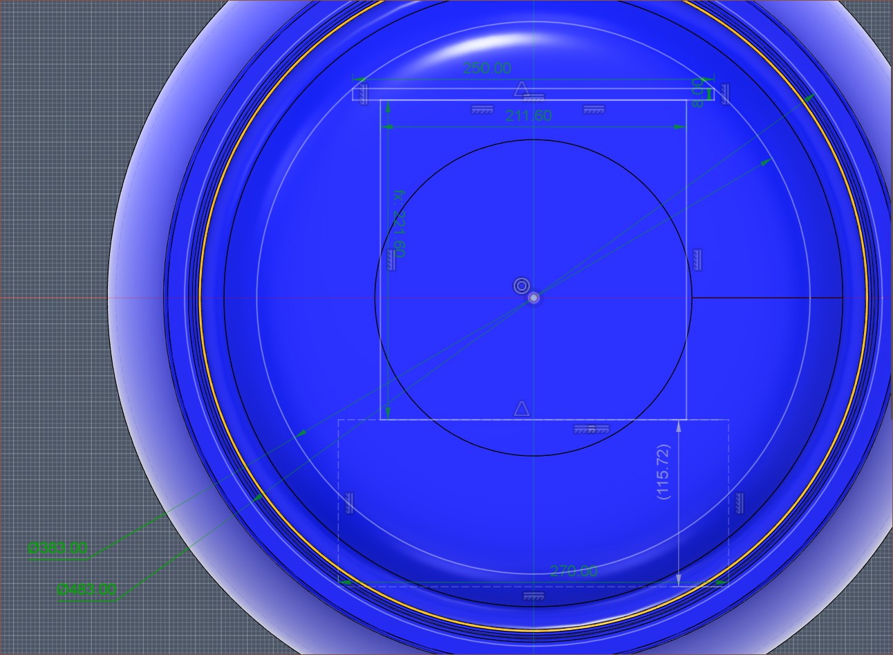
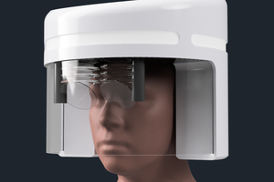
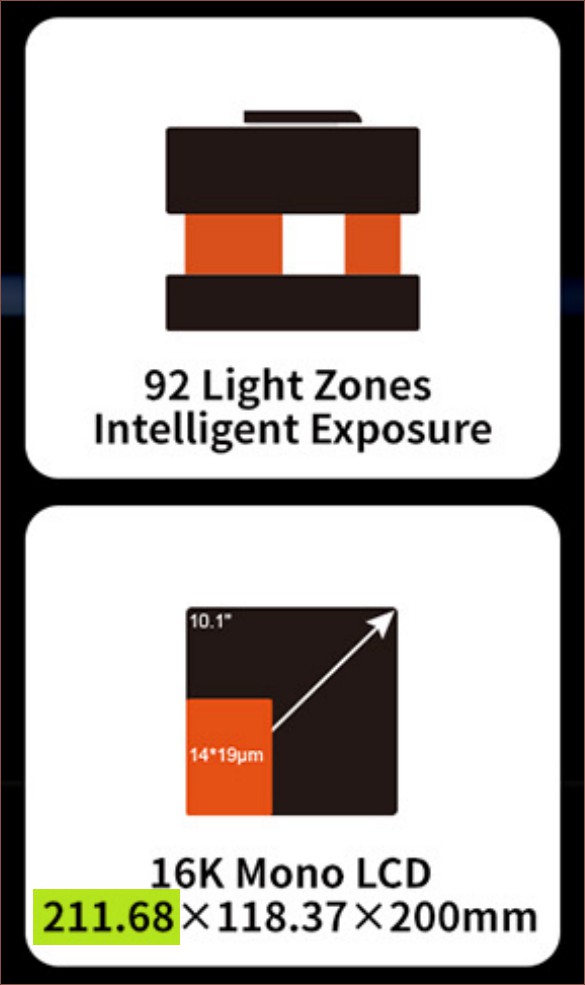 What's extremely convenient is that the Halot X1's 10.1" screen is 211mm, meaning that the print area and scanner will be very well matched. The SlimeSaver doesn't necessarily need to use the 16K screen, but it would help massively for longevity to use its local-dimming backlight, negating the higher price of screen replacement. I think I've mentioned this in a previous log, but users are seemingly happy with the quality at 35 microns, meaning that the screen chosen needs to be 6048 pixels wide.
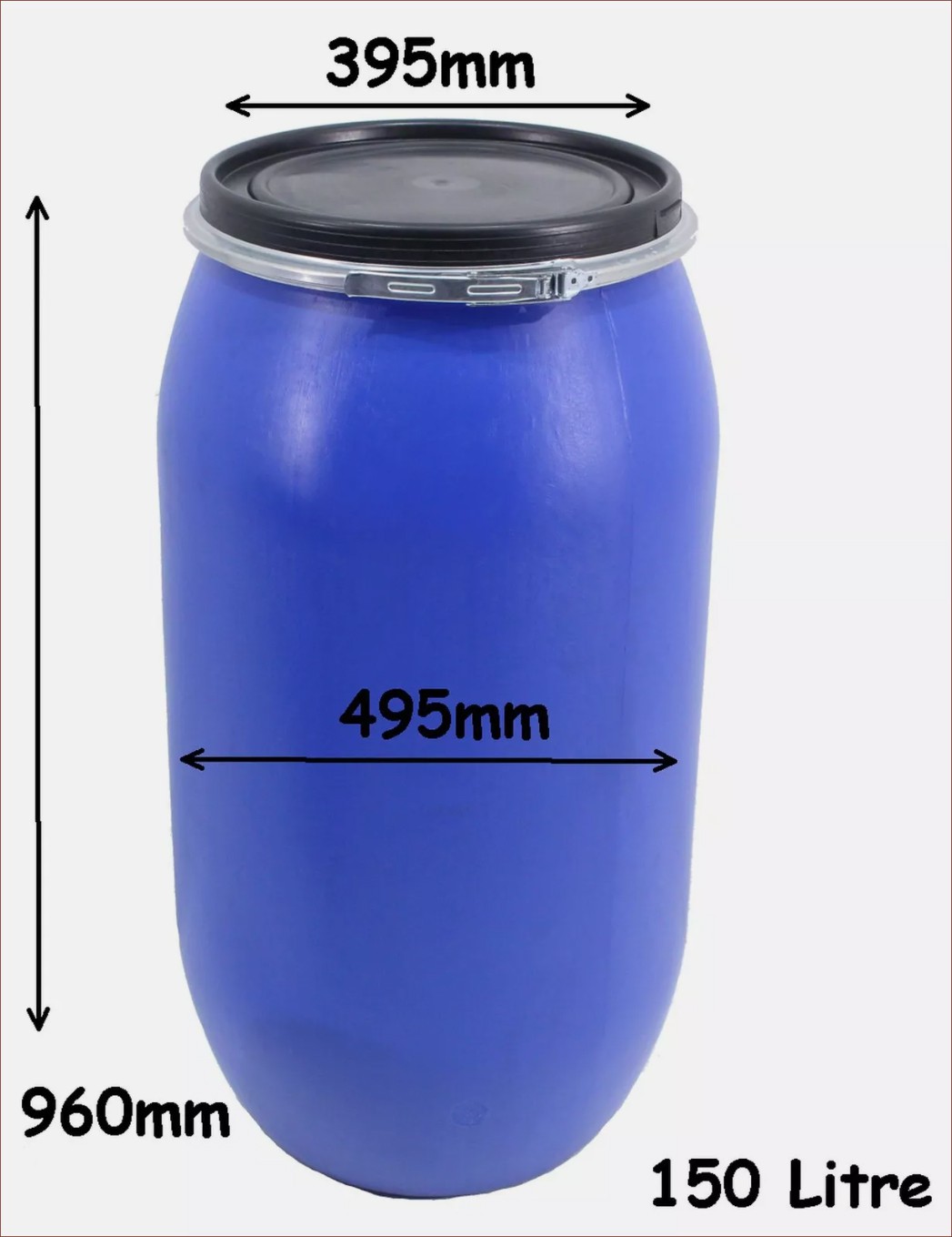
 Finding loads more papers

 Michael
Dunno if you are still working on the idea, but I was wondering about the possibility of cooling down the resin.
Conventional Two part epoxy resin stops curing at -40ºC, and a consequence of that is higher viscosity.
So, cooling down the photoactive resin of conventional resin printers may increase their viscosity well enough for viscous lithography.
Or even allowing to work with conventional two part resins since you could program the laser/projector to locally heat the resin and cure it.