I was supposed to write up this content eons back, but with the barrel literally taking months to model (a.k.a 1 day of progress every couple of weeks), I thought I'd at least get my 3rd and 4th Year projects written to Hackaday. Both projects were related to SlimeSaver, with more emphasis in 4th Year.
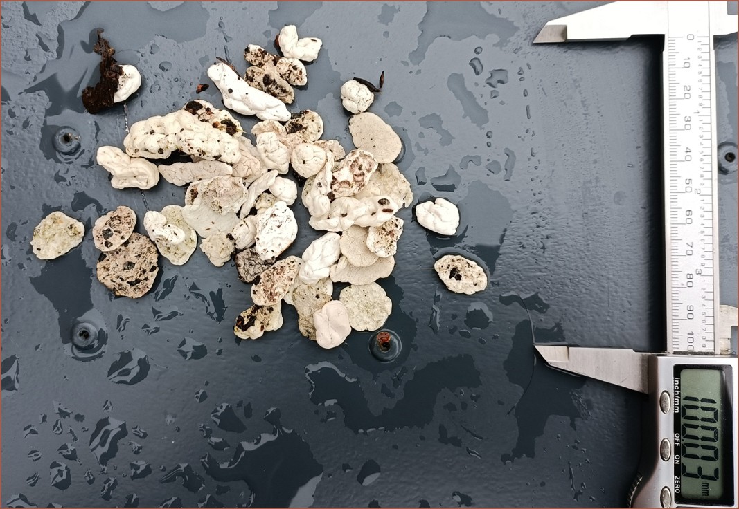
As you might be able to discern from the title of the report, the overall aim of my project was to create something like a robot vacuum but for gum on the pavements. Gum is the only thing that doesn't simply get swept away like other litter, but even a thumbnail is sufficient to scrape them off:
This is 50pcs of gum
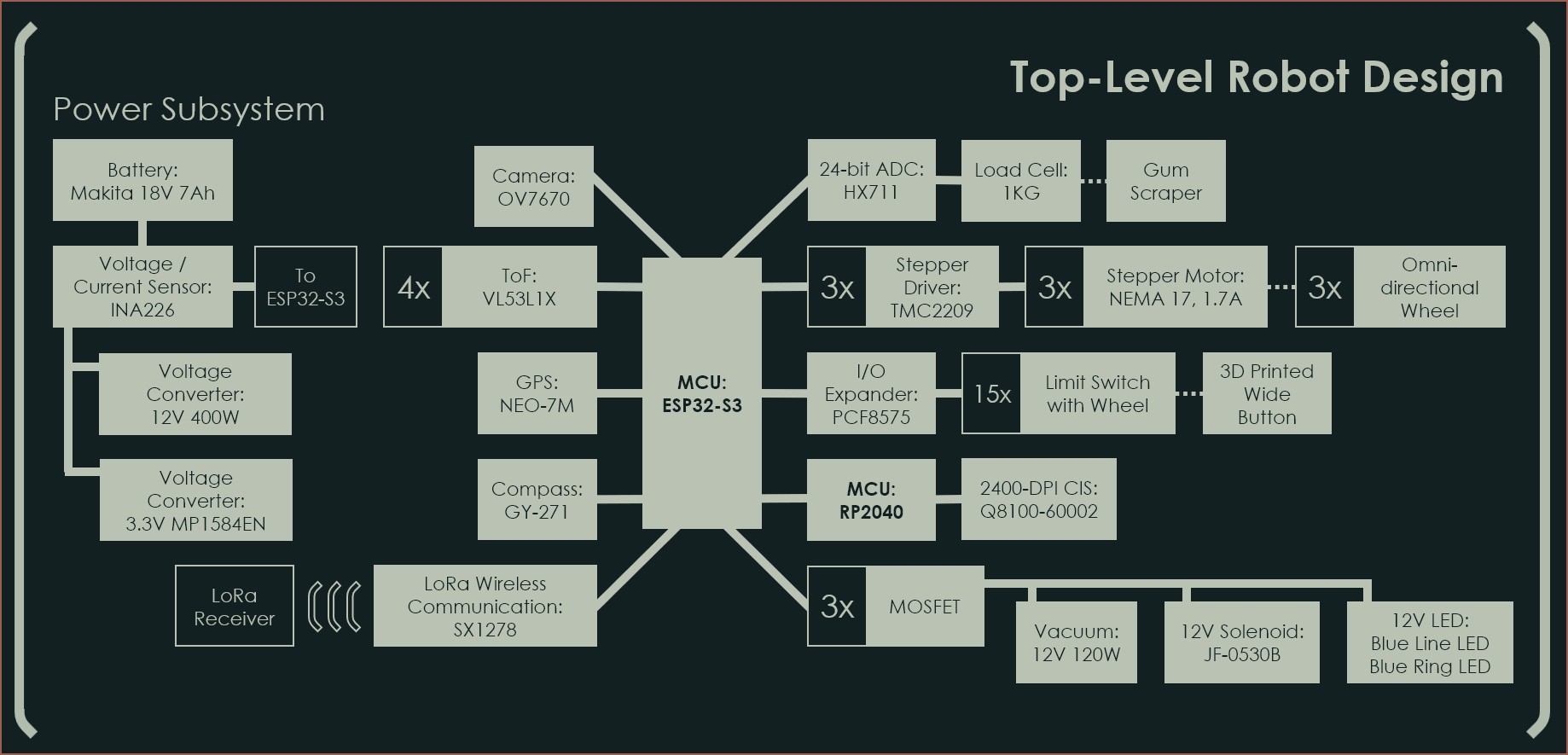
I had put together the BOM and how each component connects together:
The idea was to use blue LEDs for ground illumination since pavement is primarily grey or brick while gum is white, thus blue would have the highest contrast.
Anyway, I'd like to direct your attention to one component in particular: The Q8100-60002 Contact Image Sensor.
Yes! This was all a way to inflate the real research question: Can this CIS be reverse engineered? It's both the lowest cost and highest resolution A4 sensor I've been able to find on AliExpress, even over a year after I submitted this report.
Unfortunately the answer is "No" at the moment.
The Experiment
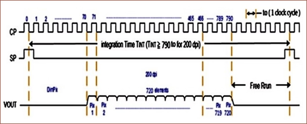
I only wrote 4 sentences about it in the report, but I had found a datasheet on the AMIS-722402 and wrote about it in an earlier log. I also saw that the M168 Module followed a similar signal pattern:
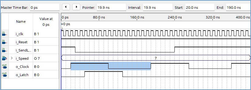
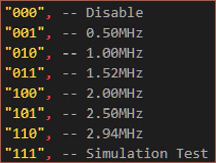
Now, since I was already doing VHDL for another module and I didn't want to learn yet another new thing, I used the De1-SoC FPGA to generate the signals I needed including a way to set the clock speed. The simulation from Quartus can be seen below:
As any 21st century kid would, I coded this whole thing in one monolith in about 2 hours to then get a lot of "VHDL says no" type errors for another 3 and a half to finally reach the plateau of productivity. Last was polishing everything in another 4 hours. I feel like things would've been even longer if I didn't start programming with easy-to-read variable names:
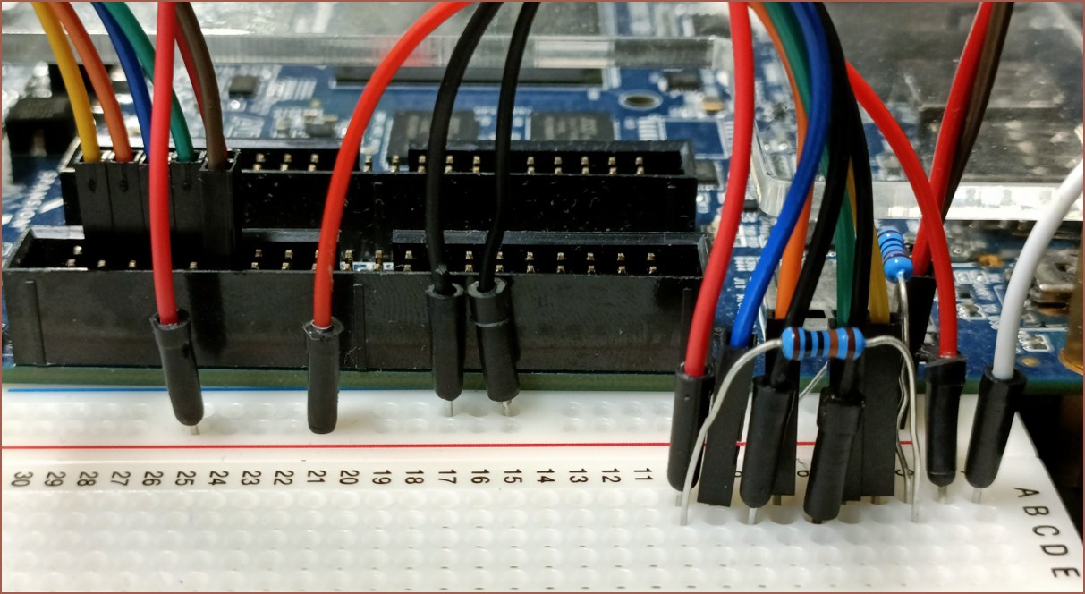
Next, I connected the circuit I needed on breadboard and tested to make sure the voltage divider got 0.3V on the VREF pin:
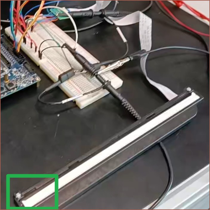
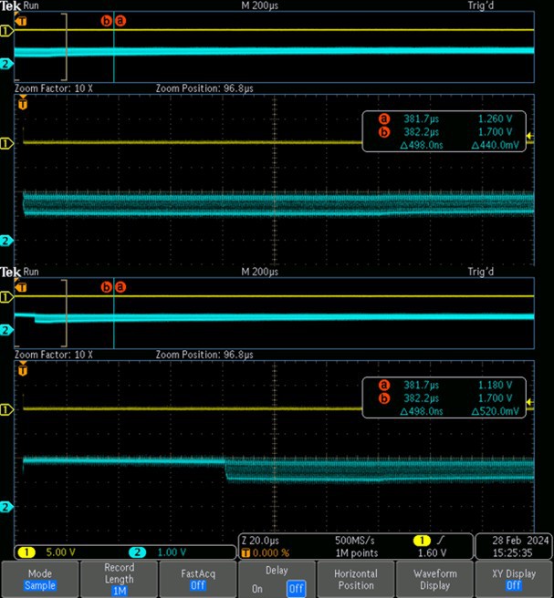
So after I confirmed the clock signals worked IRL and things, I plugged the sensor in and the green square is the only section I got an output from:
Sensor uncovered (top) vs sensor covered (bottom).
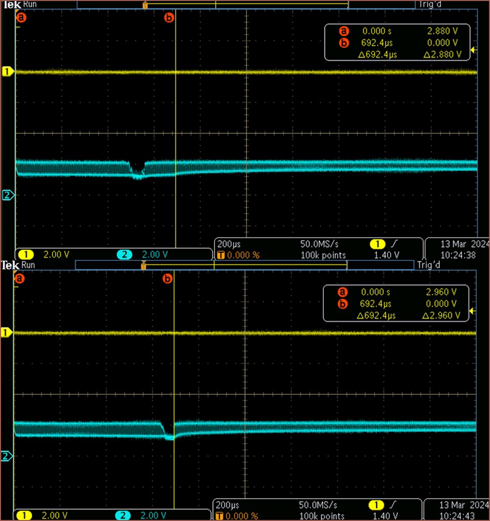
I actually found the exact point where the reading stops, as marked by the yellow "b" line:
Looking inside the sensor
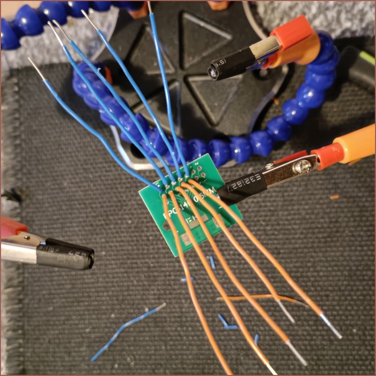
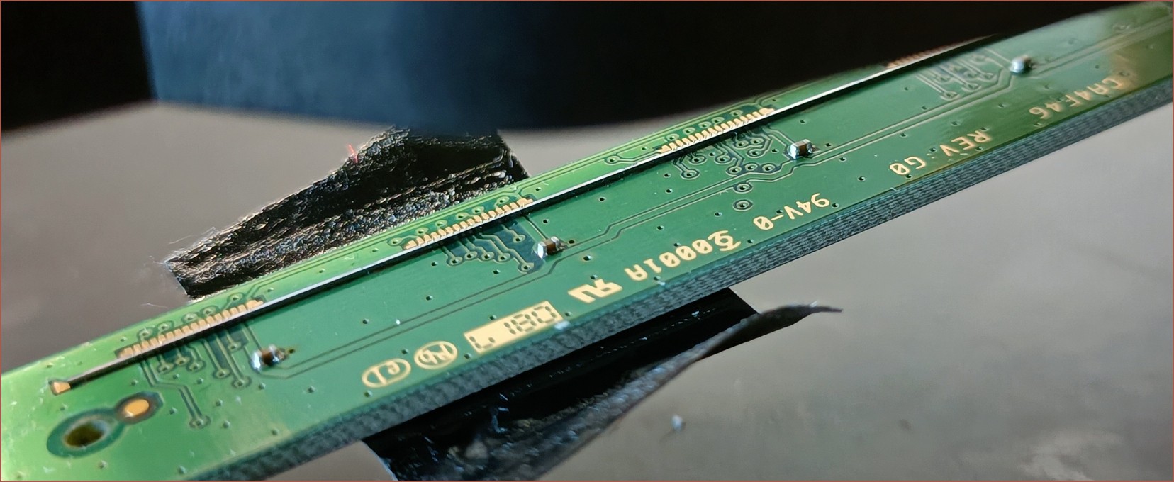
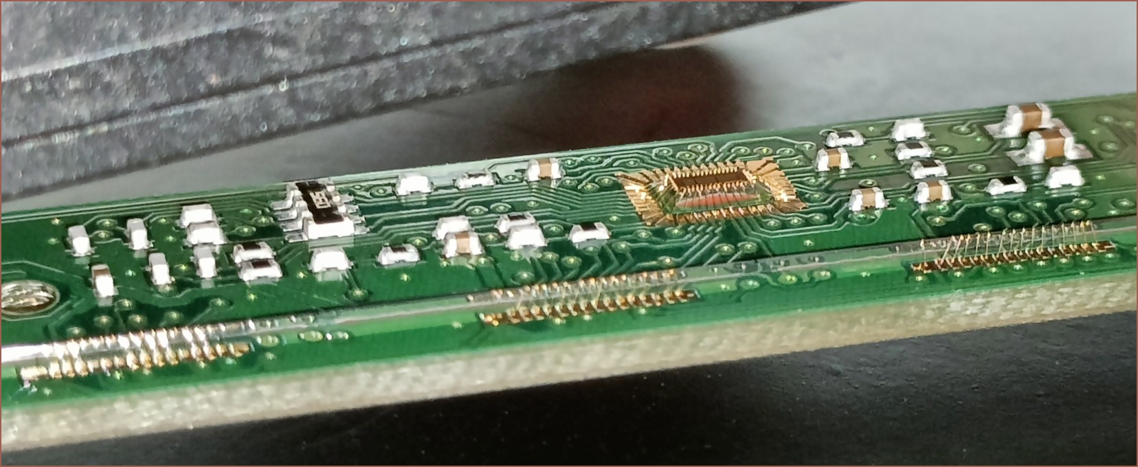
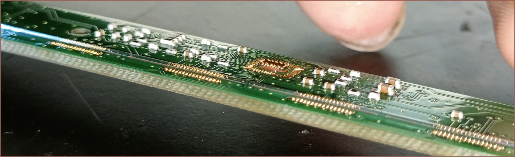
While I was trying to reverse-engineer, I had some peeks inside the sensor itself:
I don't think it helped in reverse engineering but it was nice to see all those thin gold wires. I noticed that there were 16 pads for these CIS but only 13 in the AMIS datasheet. I also think communications are going through that chip in the centre instead of being daisy-chained through each CIS. I get the impression from the readout that I'm stuck reading CIS_0 or something.
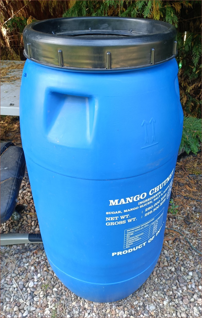
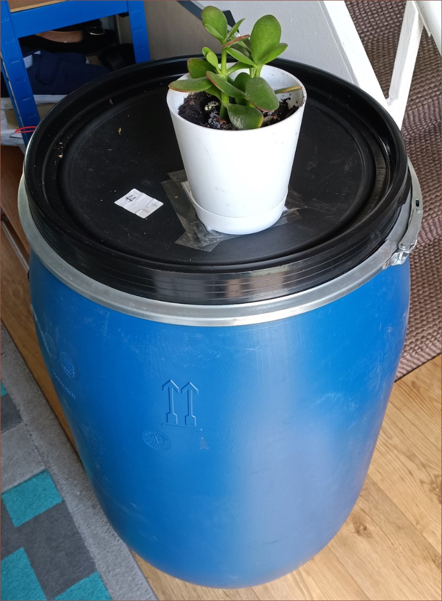
I still struggle to fathom how some companies somewhere need not one, but multiple barrels of mango chutney.
While jumping through Ebay's "similar items" section within listings, discovering "wood barrel ice-baths", I found out that there's one semi-common HDPE barrel that is taller than the 220L, blue and doesn't use a galvanised metal clamping ring: the 290L barrel. Like the previous barrel, this barrel was acquired to store things outside, thus it's beneficial that the ring is made out of plastic. For safety with a 450/405nm laser, blue or white is more ideal than red, dark grey or black. It's also got 4 convenient indents to carry the barrel.
Cleaning the barrel
The one I found happened to be local; the going rates for both 220L and 290L seem to be sub £40/ea when collected instead of delivered.
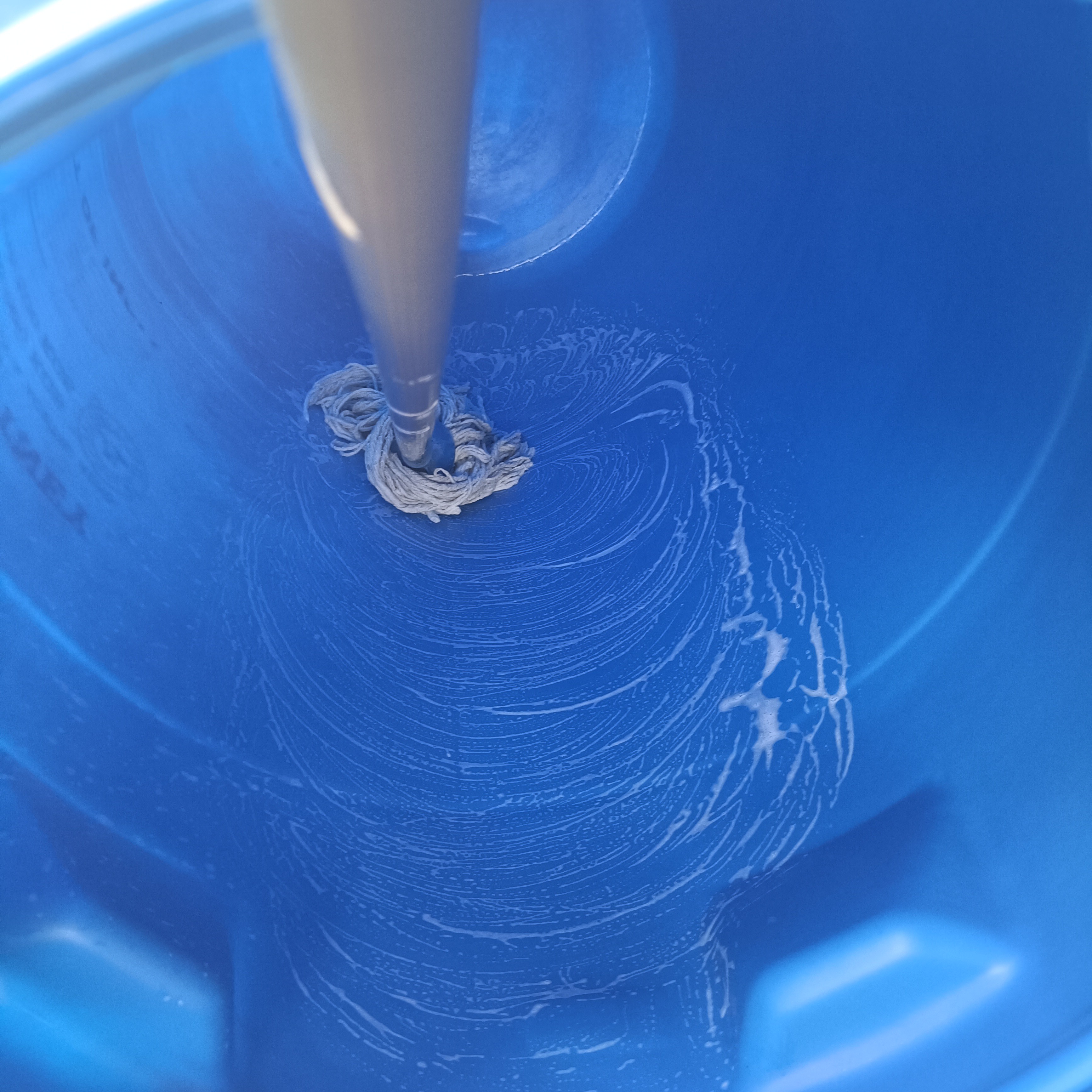
The black HDPE parts and the barrel's outside was scrubbed with a sponge and the inside was mopped:
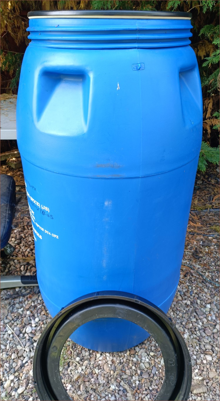
It's a 3-part assembly that is about 1115mm tall. This image was taken before cleaning.Inside of barrel before being mopped. It looked rather clean, and I think the base looks a bit more orderly than the 220-litre. Allegedly, these 290L barrels were used to transport orange juice. but it smelled like a new car mixed with something else that I can't identify.Mops don't work on walls, so I rotated the barrel 8 times to get around everywhere.
Modelling
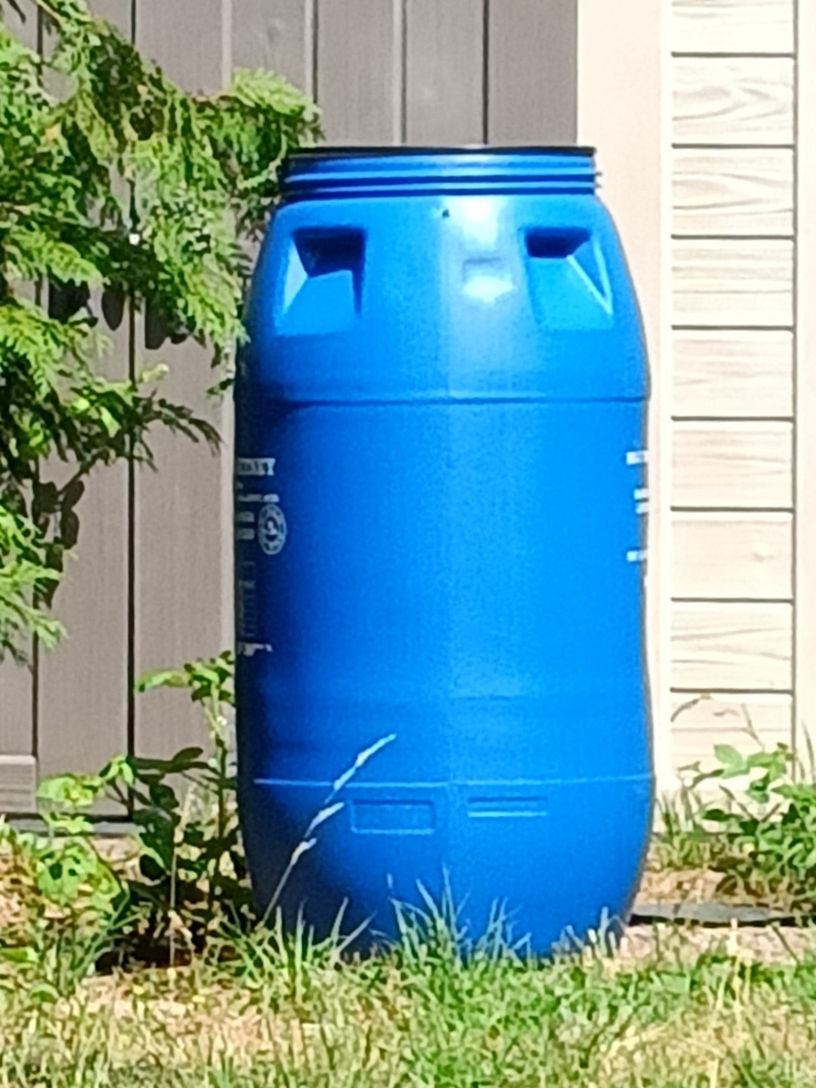
I let it dry while I measured things for 30 minutes, mainly the height. I know it's taller than 1110mm but maybe 1120mm or less. Nominally, I got 1115 - 1116mm. Then I went to the other side of the garden to try and get a full-size image as orthogonal as I could so I could import the image in Fusion:
I used a measuring tape against the branch, the wall and the barrel itself to get my 1115mm height estimate.
Taking a picture from so far away highlights how surfaces on the barrel aren't as straight as they might appear when closer. I left the lid on because I imagined that I could use its height as a reference, but now I think I'll just measure the height of the barrel's straight section.
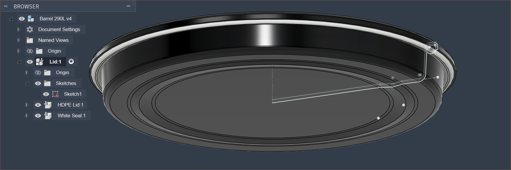
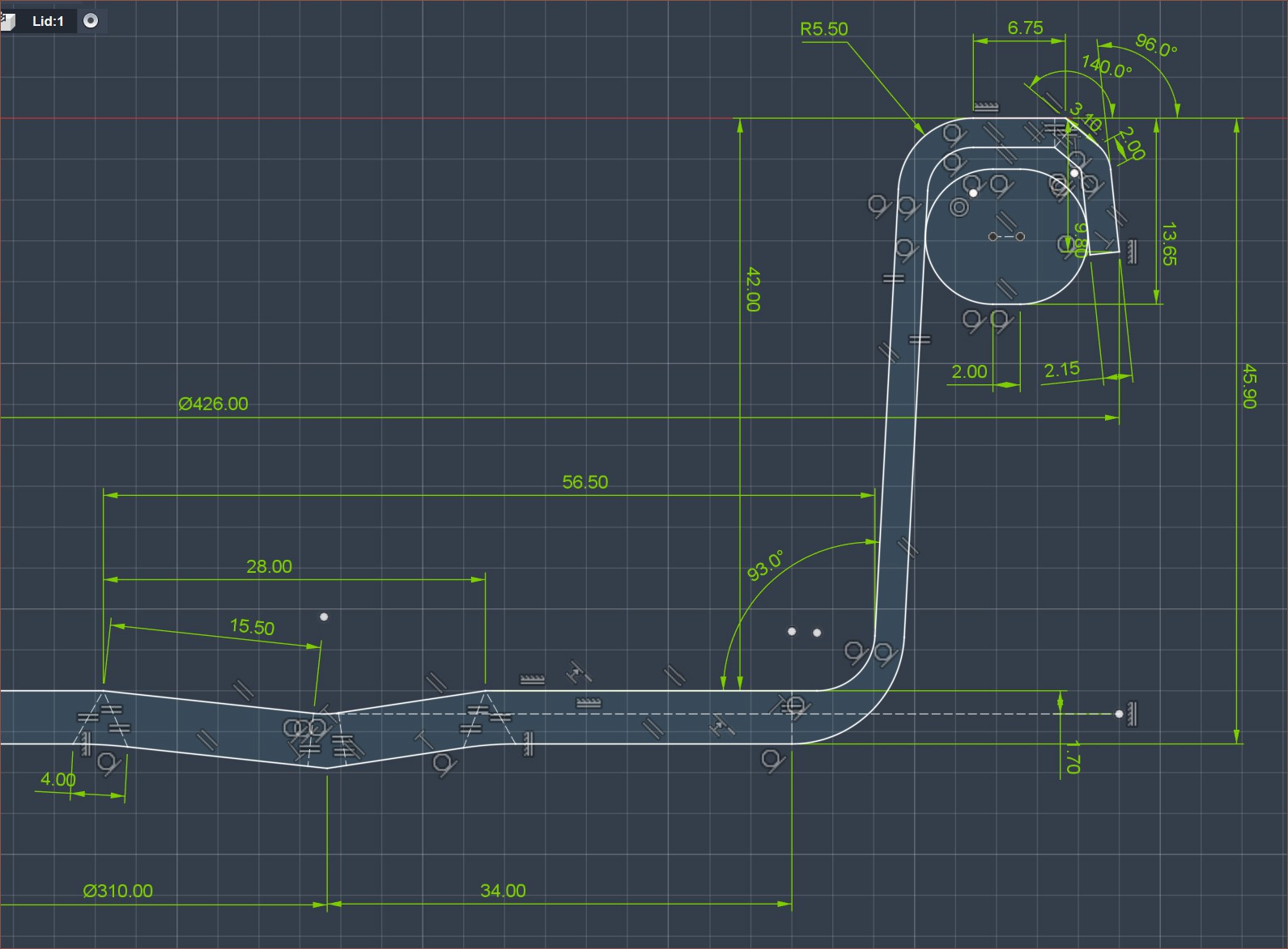
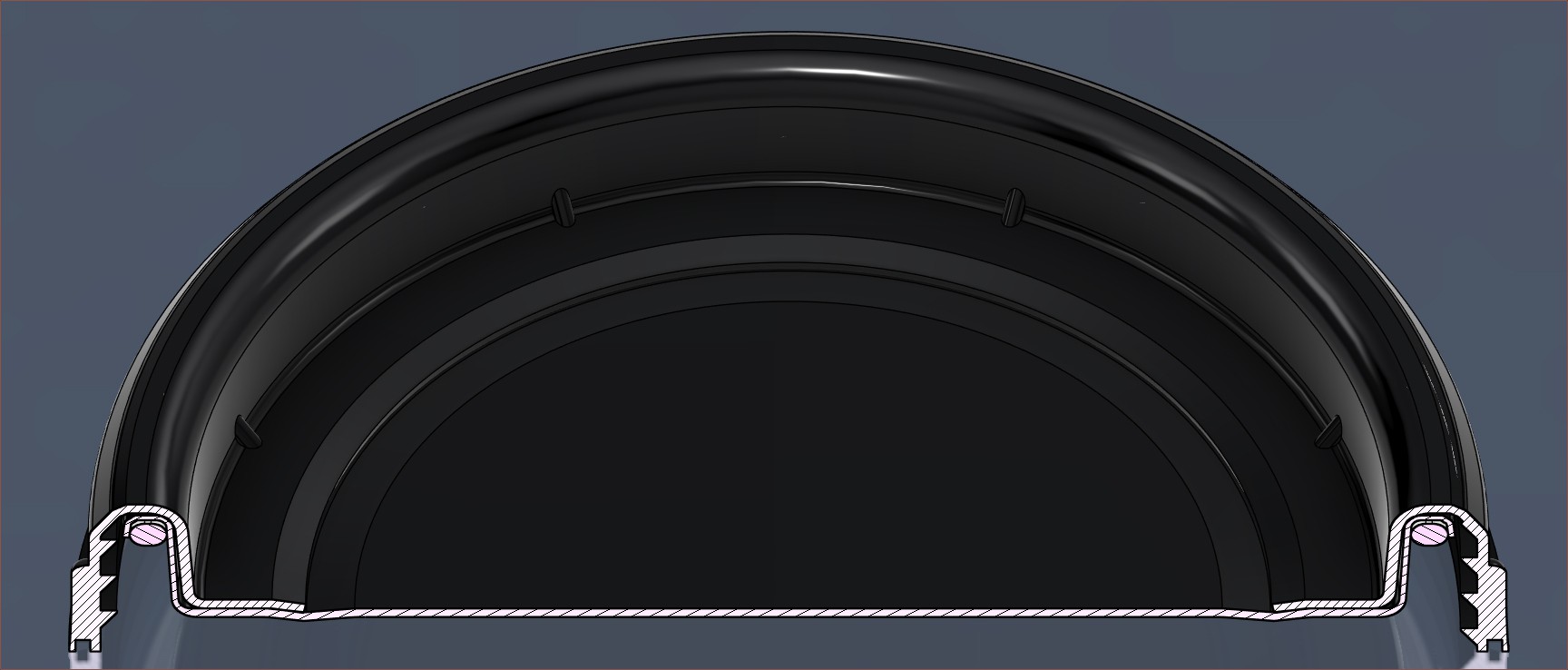
I then spent over an hour modelling the lid:
It took ages to determine where fillets started and ended, and I had to use some 48mm tape as a spacer to be able to use my calipers to measure the wall's thickness and height. It's rare times like these where I wish I had a 3D scanner. Fusion's weight estimate is 750g and the real one is 100g less, and I believe some of that discrepancy is because I don't know the cross section of the seal. The HDPE lid alone is reported to be 600g in Fusion.
I have yet to model the other 2 parts.
Trivia
I also tried using Wispr Flow for this log, but ran into similar issues as when I tried Windows Dictation over 2 years ago. I have to think of the sentence, send it to my mind's Speech Processing Unit, say the sentence, read the sentence and correct it. The first 2 steps is the bottleneck because I don't think of sentences synchronously, so I generally have to think of the entire sentence in my mind, recite it, and then say it.
Maybe this workflow is a lot better for people who can literally just say what's on their mind? It's still better than Windows dictation because at least I don't have to worry about punctuation and the default CTRL+WIN shortcut is a lot less cumbersome than WIN+H.
[July 30]
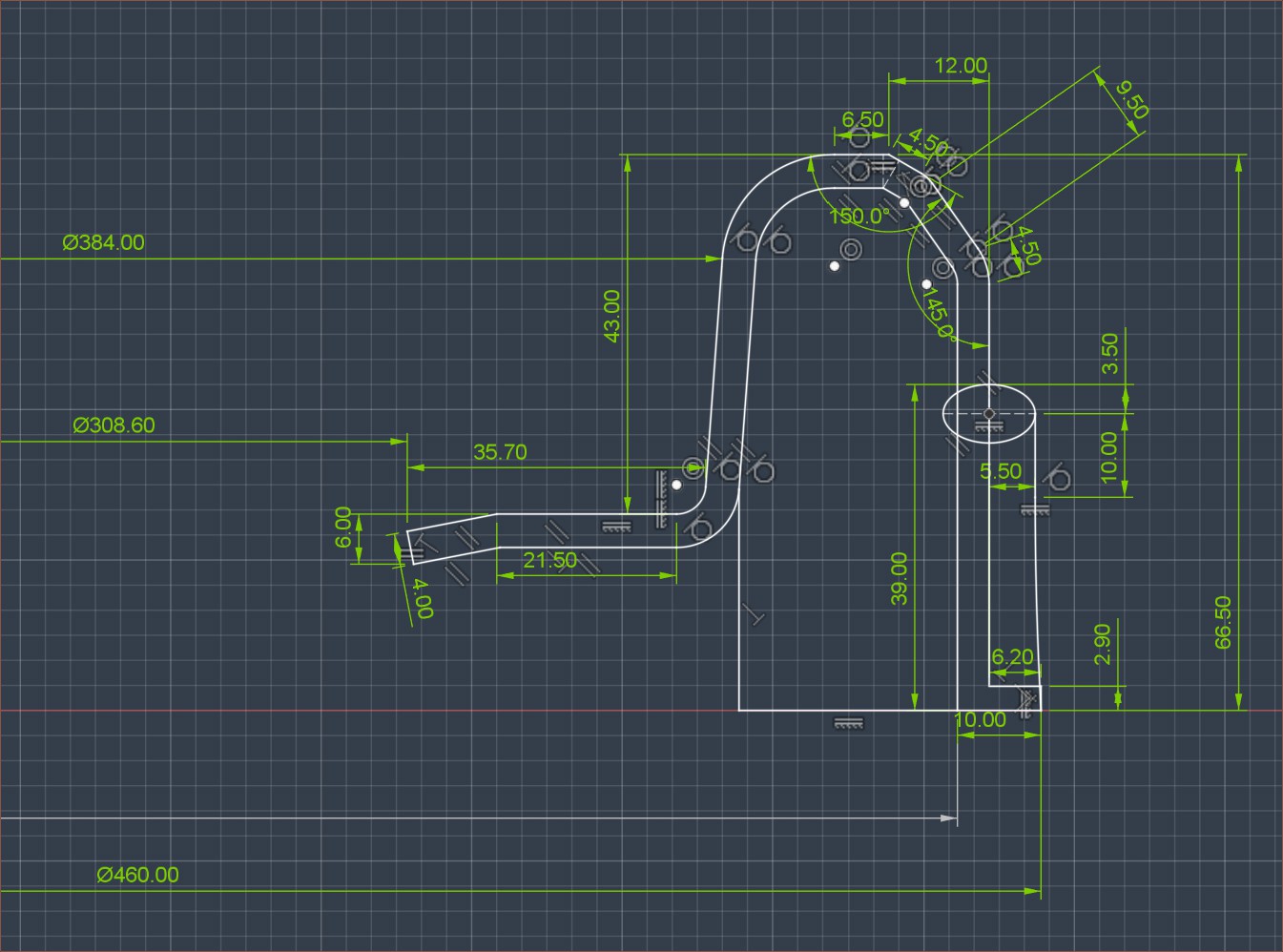
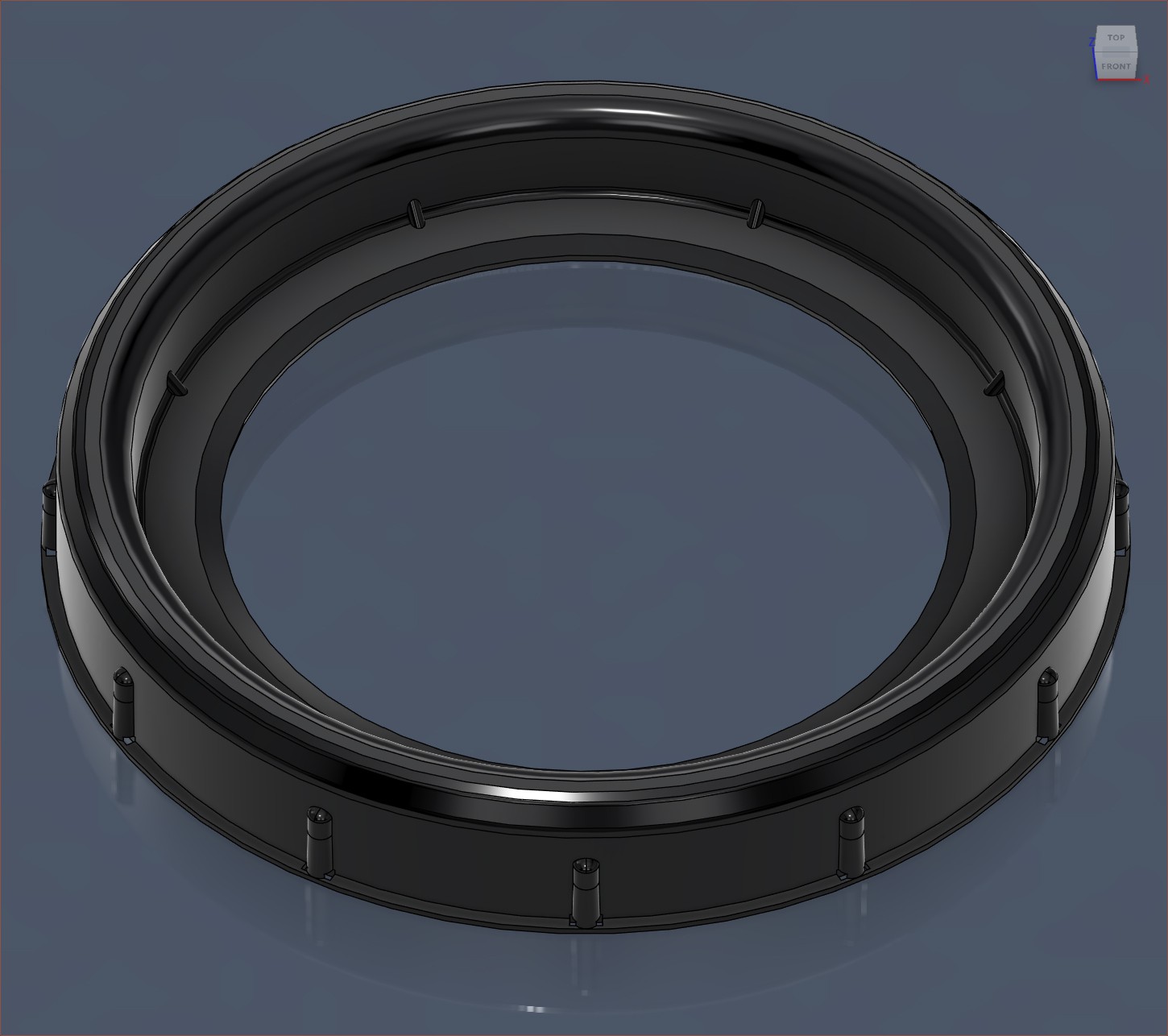
Modelled the screw ring
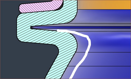
Cross section of ring and lidI've modelled the ring and kinda see how they're supposed to mesh together. It seems like it aligns with the lid modelled previously.Cross section of the plastic ring
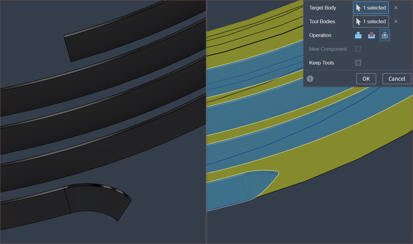
Then I had to do some tricks here and there to properly design the custom thread:
Left: Adding the curved start. Right: Combine intersection to trim away the excess.Complete ring
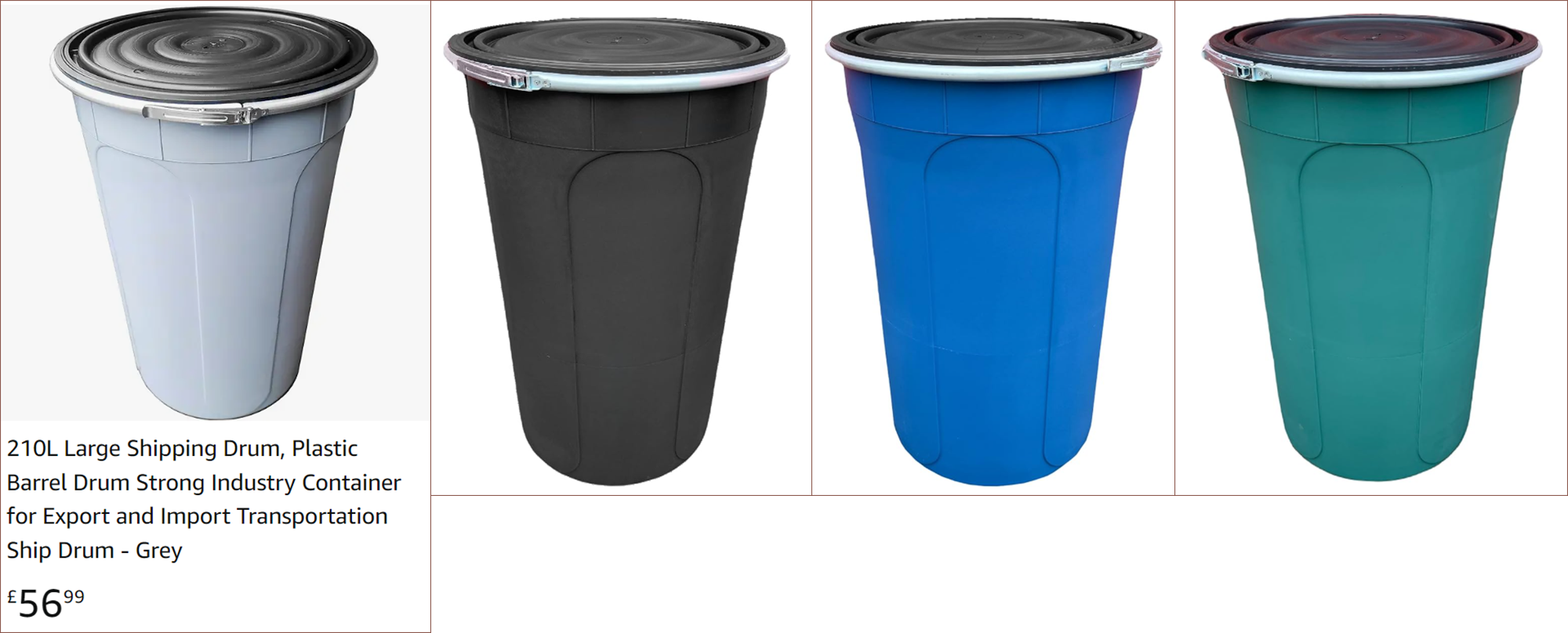
While I was writing the conclusion of the previous log, I came across this barrel that comes in 4 unique colours for some reason, such as light grey or turquoise:
The dimensions are allegedly 500mm on the base, 660mm at the top and 940mm tall. It certainly looks like a more-ideal spread of those litres in terms of fitting components inside, and my opinion is that the light grey does look particularly home-like. Looking at the levels, the light grey is also even more reflective of blue than the blue barrel.
The obvious drawback is that the clamping ring is even wider, as well as the entire barrel, requiring even more space. It seems that the ring has a more curved shape and doesn't overlap when closed.
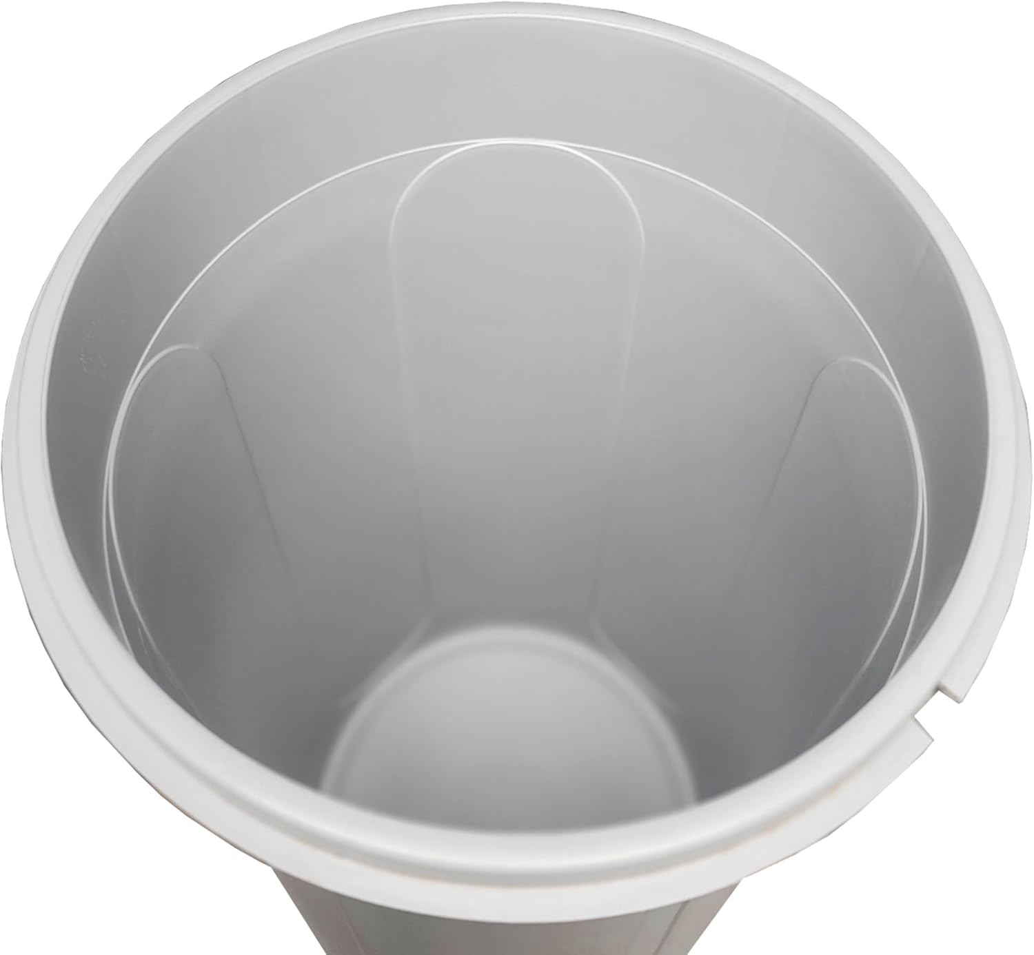
The inside for the light grey looks nice. I don't think it would be all that much harder to clean the edges inside. I just wonder if it's as solid as the typical barrels considering there's a £20 price difference. The cost might be because the walls are thinner, or the seal isn't airtight, or perhaps it's simply that they can save on shipping costs because these cone barrels can be stacked.
One thing led to another, and an allegedly "new" barrel arrived:
The ring was slightly rusted here and there, and the outer wall had some thin layer of mud/dust? Not a particularly inspiring first impression. I asked the seller and they apologised for the inconvenience and said that this was pre-used.
Barrel body and lid: 4.5 / 5 stars for suitability as an enclosure
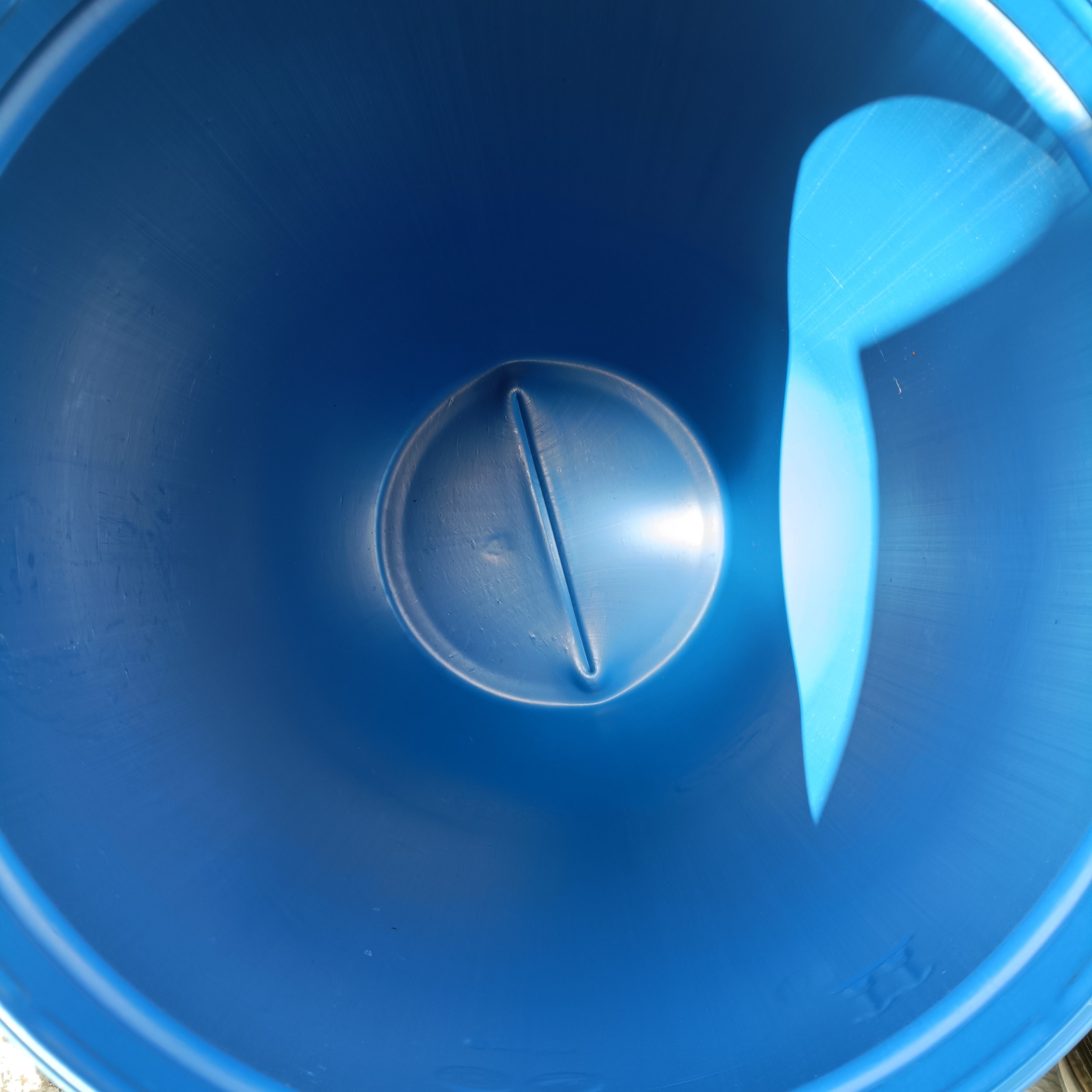
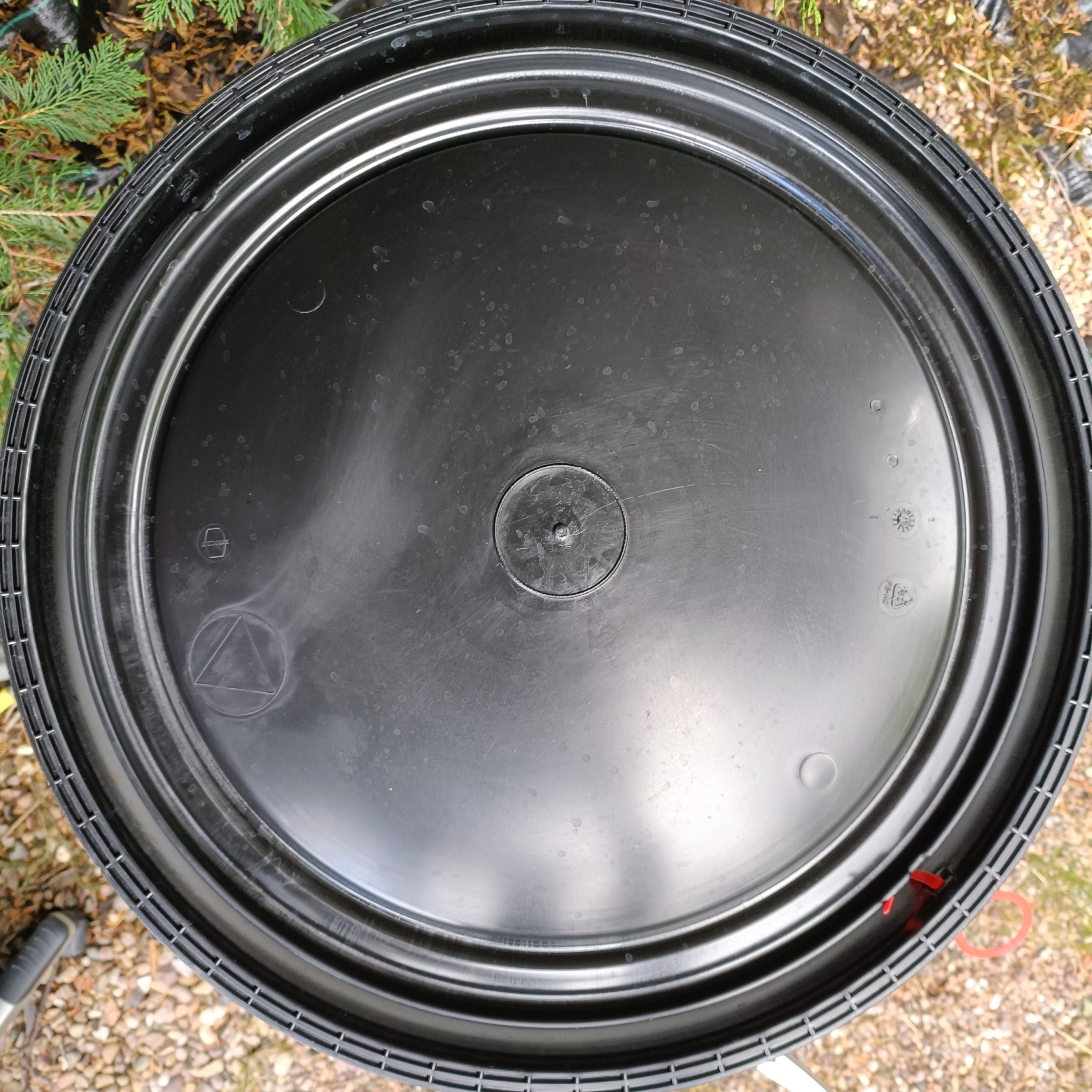
The inside of the barrel and the lid looked fine enough:
I did some knock tests and it's certainly some solid plastic. It's not some milk carton or 4mm pane of polycarbonate. It might look like a supersized yoghurt bottle but it's stiff like a desk.
That 3D line thing at the bottom is raised 1cm and likely remnant of the fabrication process:
You can see in the video that it looks a lot floppier when the plastic is hot and going inside the moulds.
I also learned that the sealing is done with a white o-ring instead of the flanges, as implied by the CAD model:
Some of the measurements I noted down (in centimetres):
Body
>43 for bottom diameter
46 for the bump diameter before the opening (see Eccentricity below)
>58, likely 58.5 for the widest internal diameter.
59.5 or thereabouts for the outer diameter.
36 for the vertical section
95 from the middle line to the rim of the barrel
94 if from the bumps
46.5 - 47.5 for the opening (see Ovality below)
Lid
48.5 diameter for its tallest feature (that looks like a wall)
23 out from that wall-like feature as the handle clearance
1.8 between bottom of body flange to the taper of the lid's flange
The barrel has a slight amount of eccentricity, ovality and coning.
Eccentricity:
The bump is a circle, but one side has the bump aligned with the opening and the opposite side extends out (white line) by about 1cm.
Ovality: It's only 1cm. I think the lid flexes when it goes ontop of the barrel.
Coning: Like a standard plastic bin or a plant pot, the "straight" section of the barrel slightly cones out. Maybe the angle is 1 degree or something so that it can release from the mold.
All these things are kinda minor, and other than the seam line at the bottom of the barrel, it looks rather easy to wipe down. Its rigidity also inspires a lot of confidence. Furthermore, the roundness means that, while large, the barrel can fit in an outer corner:
Like it's "big" but it feels like it needs less "personal space" than a CR-10, for example.
Clamp ring: 2 stars
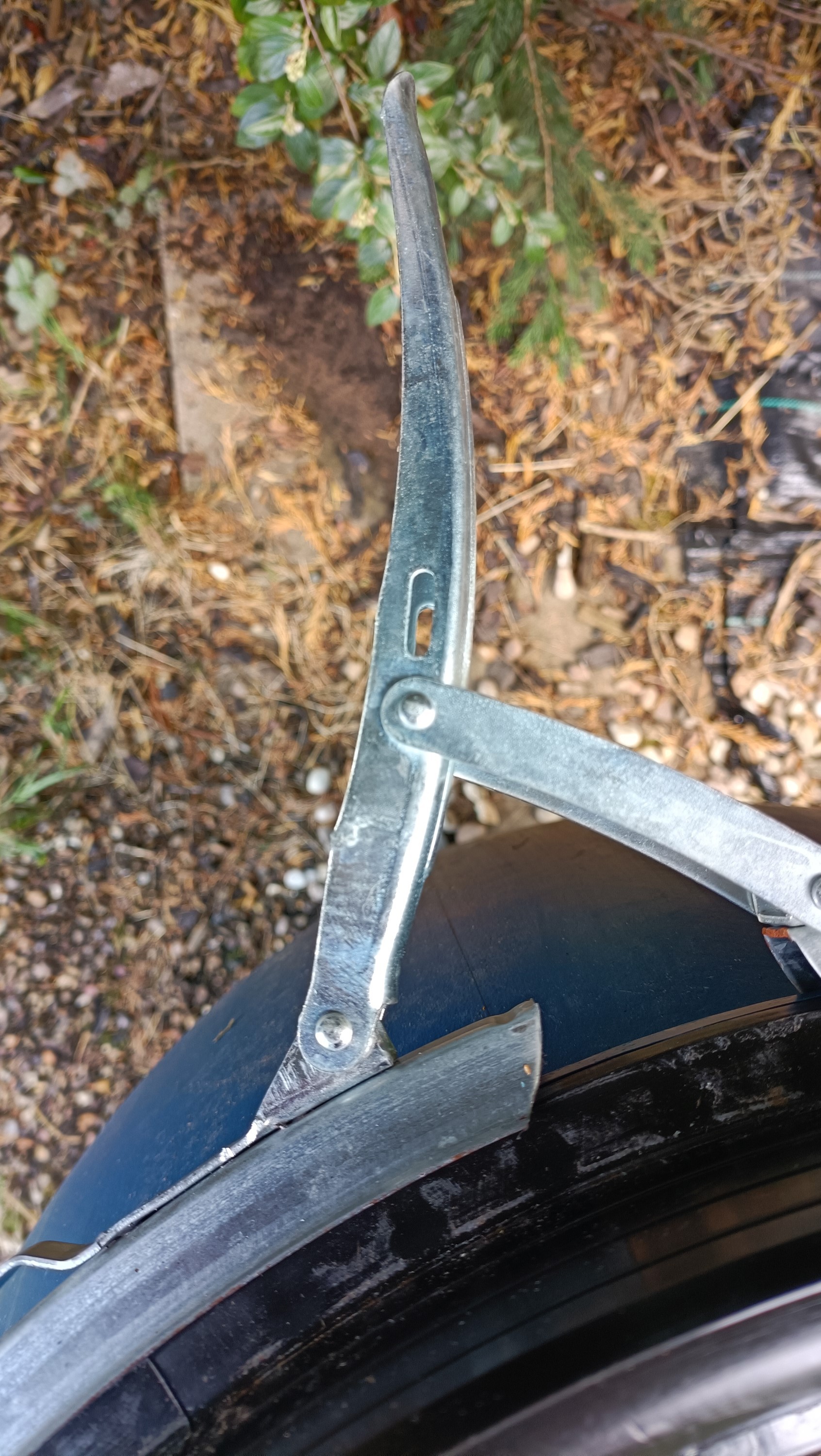
Unfortunately, I've sent the barrel back because the clamp ring was too hard to work with. It's super easy, barely an inconvenience to open the lever and take the ring off, but the other way required levels of force I just didn't have. My brother did, but he had to take a stance like some kind of superstrength superhero when closing the lever.
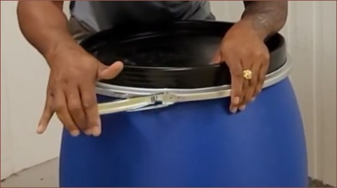
One of the first issues is that all the hinges are loose-fitting and the ring isn't much taller than the thickness of the flanges. As seen in the below video (at 3m 0s), you need one hand pushed on the lever to expand the ring and then align the entire circumference so both flanges. With practice, it probably would be less of an issue.
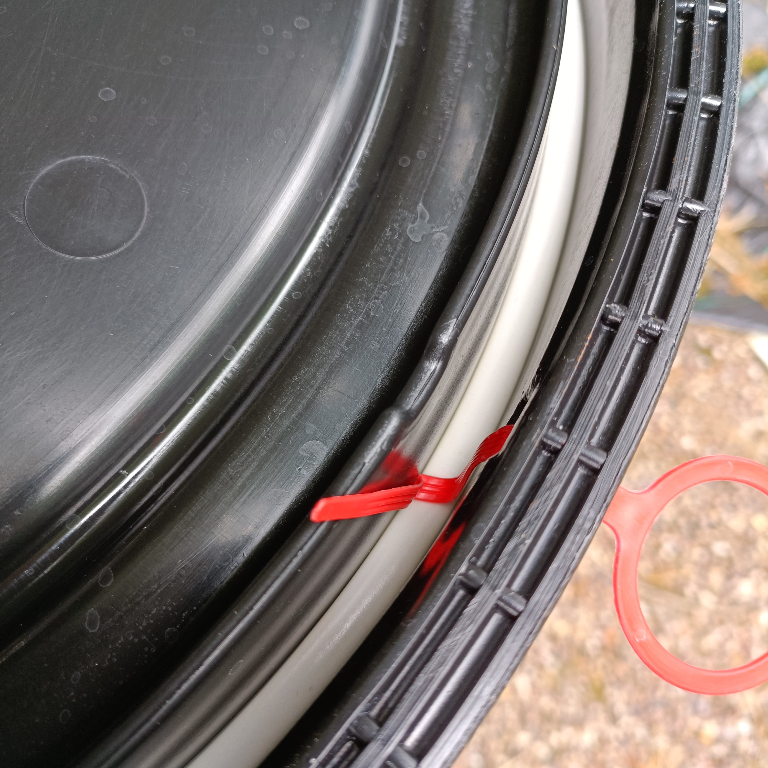
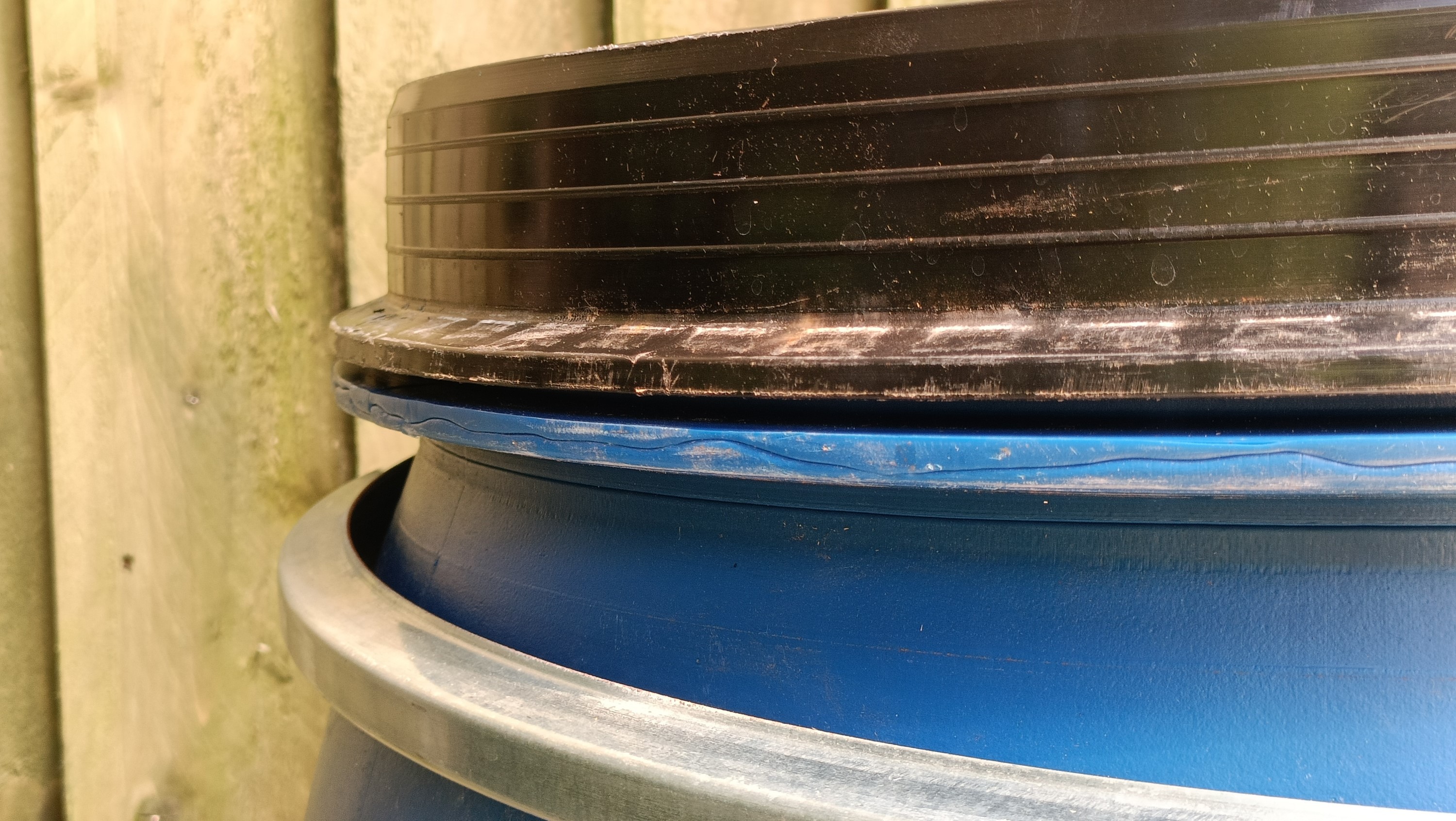
I haven't seen a close-up image of the barrel without the metal ring on the internet, so I took a picture. Below, you can see the kind of gap between the lid and the body flange, as well as artefacts in the body flange due to the manufacturing process:
Maybe the ring isn't the one that came with this particular barrel but another one where the height difference is smaller? The guy in the above video seemed to have a much easier time closing the clasp.
Another issue is that an additional 23cm of space from the lid ring to a wall is needed to have enough space for the lever:
This wouldn't be an issue if I didn't have to put my entire body weight on the barrel to stop it from spinning due to the high angular force applied, meaning that the lever would have to be facing away from me:
For a barrel that's easier to close than the one I got, it still seems like it's easiest to close the barrel when the lever is on the opposite side to your body.
I did wonder if I had the ring upside down or something, but the ring looked symmetrical and both orientations had no effect on difficulty.
Understandably, this lever clamp ring was designed with the assumption that the user would have ample amounts of space around the barrel. Contrast to this, I'm planning as if a user just so happened to find a 60cm slot between a wall and a fridge and can only access the machine from the front.
It's also not ideal that the ring is both merely galvanised (meaning that, as seen, the underlying steel has opportunity to rust) and kind of thin (not quite thin enough to cut, but certainly worrisome).
Conclusion
Either a new way or clamping would need to be engineered (as that's how the vast majority of barrels are secured) or a barrel with a screw-on cap would have to be used for this to be a good user experience as a 3D printer enclosure. Even if this project only gets to a "university research project" level of polish, the clamp I got is far from ideal.
The barrel is ideal in most other aspects: It's blue so a diode laser can't easily poke through, it's very sturdy, it feels a bit gamified (aka getting drops out of a loot box) and it's a commercial off-the-shelf, low-cost solution.
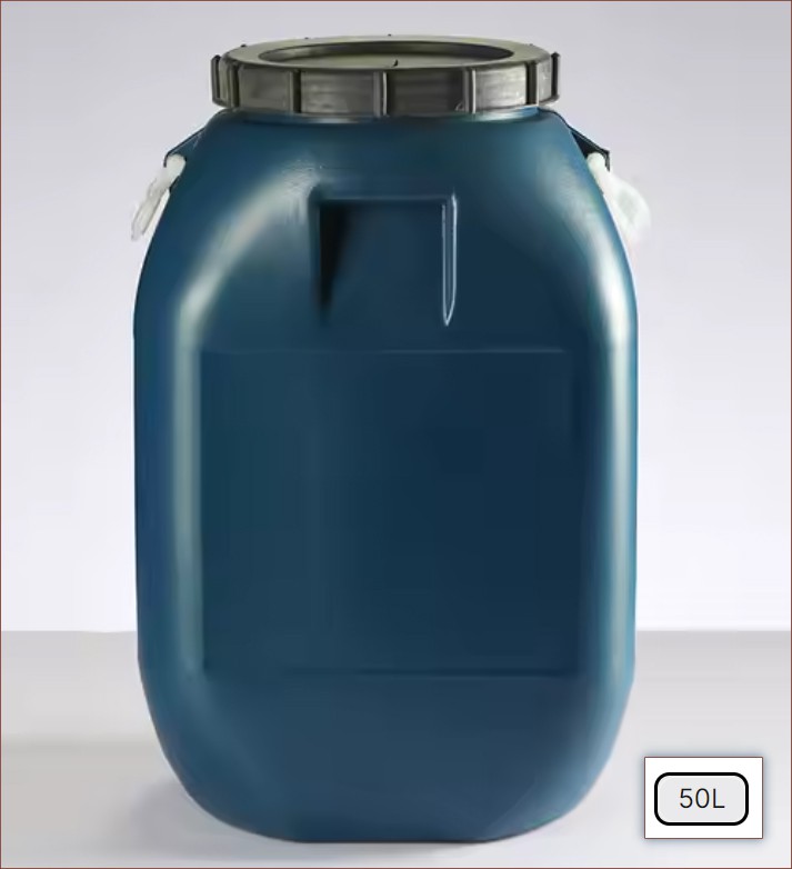
If I could magic up a barrel, it might be a 4X larger version of this 50L one:
I would've never expected that barrels were made in this sweet, seaweed colour. It's like my render background colour. Understandably, a blue laser likely will burn through this colour.
However, it's not like a screw-top is without its potential drawbacks, namely alignment with the threads and a loose fitting being much less obvious.
Next, there's a company called BERGER that has clamping rings as their entire business model:
Since 1950, the supplier of the packaging industry has been manufacturing 4,000 different clamping rings. The great advantage of clamping rings lies in their ease-of-use: They can be opened with just one hand. BERGER manufactures clamping rings with a material thickness of 0.5 to 2.0 mm in [galvanised] steel and stainless steel.
Thus that at least implies that some barrel somewhere uses a stainless steel clamping ring.
Moving on, these ITP Packaging guys that made the video below are one of the handful of sellers on Amazon, with the market all within the £70 - 75 range.:
After seeing both videos, my current hypothesis is that the ring I got originally was for a slightly different barrel with slightly smaller spacing between flanges, resulting in unusually high forces required to close the lever when installed onto the barrel I received. The man puts the ring back on at 0m 39s without any particular effort but still seems to require a rather ample amount of space to thread it onto the barrel, so that's something to keep in mind. I also never found any reviewer that voiced any difficulty with the clamp ring.
Detecting if the barrel is sealed seems like most tamper-proof method of ensuring safety. This is because I remembered what was said in a BambuLab interview about the H2D:
True story that one influencer tested the printer [and] write us a message to say:
"I really want to open the door to shoot a footage of the laser engraving and I know you have some sensors on the door, so I tried my best to use magnetic to cheat your sensors, but uh somehow it didn't work. Could you tell me how to cheat the system to make the door open while the laser still works?"
and uh yeah, we place lots of sensors, you know, to make sure even if the customer wanted to cheat the system, we won't, sorry. We won't allow you to, you know, light up the laser if all these security measures are not in place.
And so, similar to encryption, whatever solution I come up with for a DIY strategy has got to be somewhat resilient to spoofing whilst the entire system is known. For example, a simple door switch can be bypassed by shorting 2 pins.
With a pressure sensor, it both detects to make sure the lid is closed tightly and if air is unintentionally getting out, making the filtration less effective. My assumption will be that anyone savvy enough to program a microcontroller to send fake pressure sensor data also knows what they're doing.
I guess trying to seal both a power inlet and pressure outport isn't too demanding. The issue is that it requires components that can move air out of the barrel and then re-equalise pressure when the print is finished, which costs money and space.
I'm also reading Electronics Protection: The Unknown Problem with Airtight Enclosures (PDF), wondering if the temperature differentials of the barrel and its environment could pose an issue, and it sounds like it. Their proposed solution was "expanded PTFE" but it allows gasses to move in and out, which defeats the whole point of the barrel.
It seems that the simple and inescapable choice is to maintain a detectably negative pressure with a compressor and electronic valve, where every 30 minutes or so, the print pauses, makes sure the air is clean and then equalises the pressure before recreating the negative pressure. The assumption is that the inside of the barrel will be hotter, thus the negative pressure will slowly increase.
Some bargain bin pump is unlikely to pass my low-noise standard, especially since the pump will be going out to 1 bar. The air pump below went up from 66 to over 80 dB when pumping into the open air:
The "fixed" pump at 37s in the below video is still much too loud when pumping into open air:
Car tyre compressors aren't much better:
It seems that, on the inside, a piston system is used:
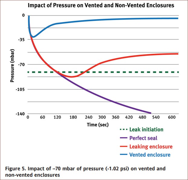
Perhaps the good old-fashioned way is to get the Y axis to push a manual bicycle pump? There was a graph in The Unknown Problem with Airtight Enclosures I mentioned yesterday where the pressure decreases and then equalises. The rate this happens will be enough to tell if the barrel is sealed enough or not.
An idea could be to have a pump that is pressed when the effector goes to the bottom, which it typically would have to do when selecting the cartridge to clear the resin so that the laser can work on the printed part.
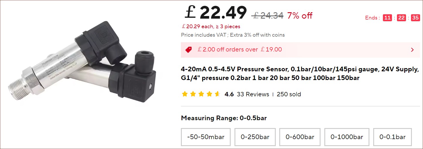
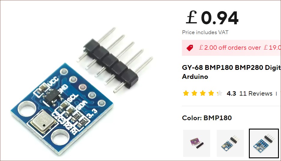
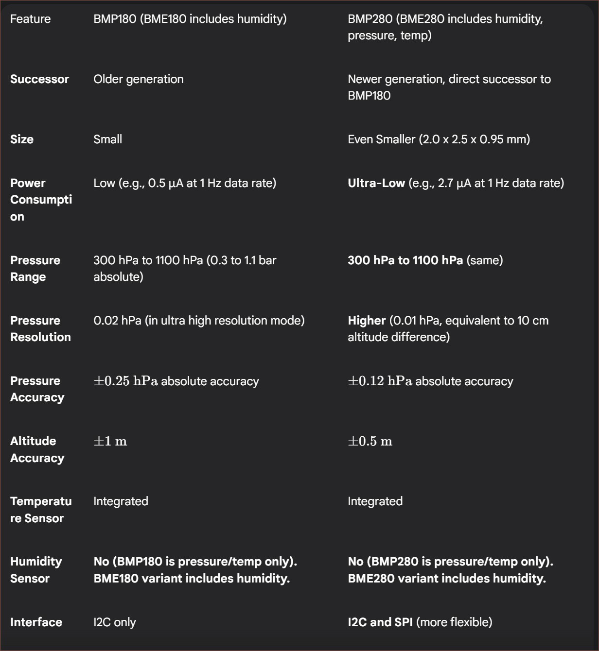
When it comes to the actual sensor, I was a bit worried when AliExpress started off with sensors costing over £20 each, but with the help of Gemini, it sounds like I should be fine with a low-cost barometric sensor such as the BMP180:
10pcs is £5
whereby
The BMP180 measures absolute pressure in the range of 300 hPa to 1100 hPa (or 300 mbar to 1100 mbar). 1000 mbar (ambient absolute) -50 mbar (gauge) = 950 mbar (absolute).
As you can see from the graph above, the drop to -52.5 mbar
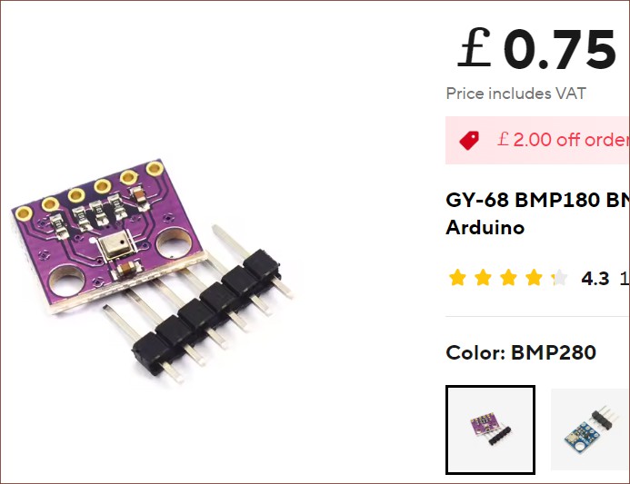
The listing also has the BMP280, which is cheaper. Turns out it's also the newer sensor with twice the resolution and SPI mode:
10pcs is £4Sounds like the 280 uses slightly more power though.
At the same time, it's not like 50 hPa is an incredibly large moat. It doesn't take much for the internal components to heat up the inside enough to return to 1 bar. There would need to be another pressure sensor reading the outside environment.
If the air is constantly being pumped out during the course of the print, it's less likely to be an issue. Gemini's expectation is that 11 litres of air would be pumped out, which doesn't sound like a terrible amount:
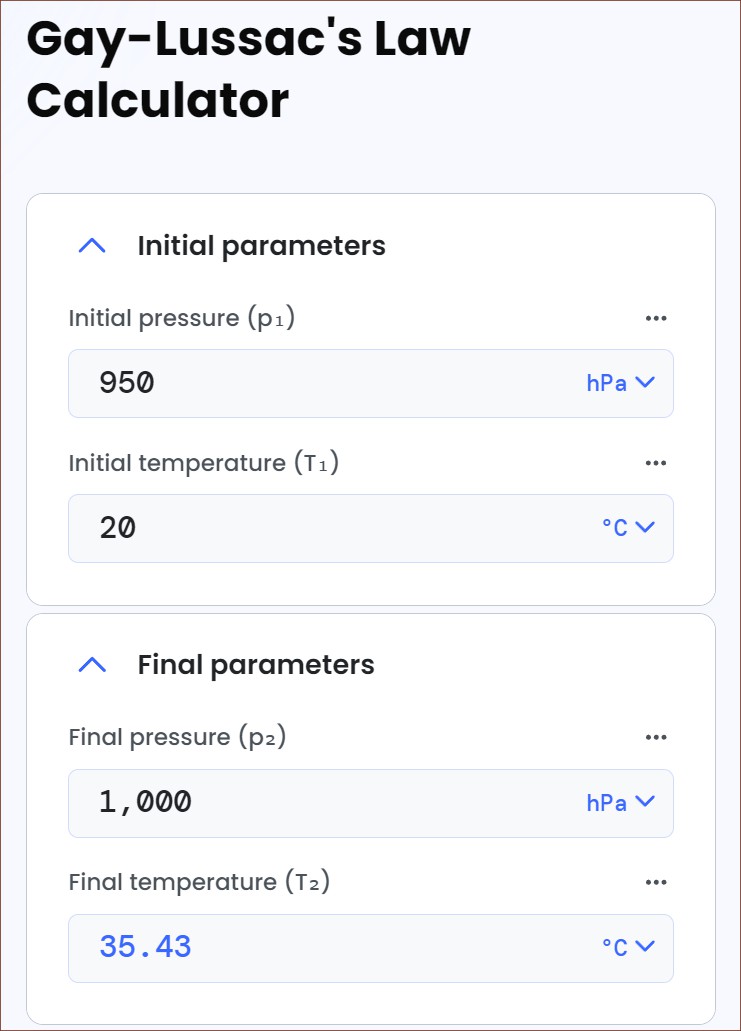
Let's use the Ideal Gas Law: PV=nRT. Since temperature (T) and the gas constant (R) are constant, and the volume (V) of the enclosure is constant, the change in pressure (ΔP) is directly proportional to the change in the number of moles (Δn).
Let's assume: -- Initial Pressure (P_1): Standard atmospheric pressure, 1013.25 mbar (absolute). -- Target Pressure Reduction (ΔP): 50 mbar. -- Volume of Enclosure (V_enclosure): 220 L.
The fraction of air (by number of moles, or effectively by volume at the initial pressure and temperature) that needs to be removed is:
Fraction Removed = ΔP/P_1 Fraction Removed = 50 mbar/1013.25 mbar Fraction Removed ≈ 0.04934
Now, to find the volume of air that needs to be removed (at the initial ambient pressure P1 and temperature), multiply this fraction by the total volume of the enclosure:
Volume of air to remove = Fraction Removed × V_enclosure Volume of air to remove = 0.04934×220 L Volume of air to remove ≈ 10.85 L
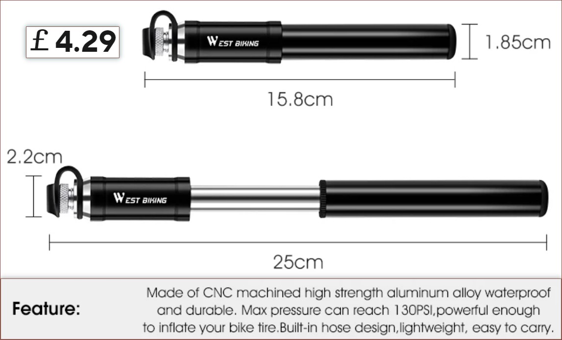
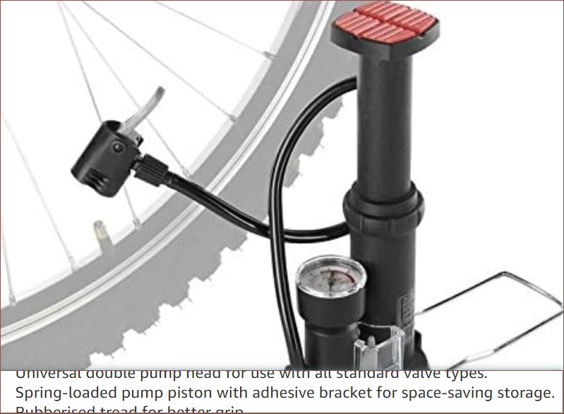
As for the pump itself, it seems that AliExpress has this West Biking one for around £5:
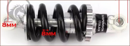
For simplicity, a spring could be placed around the circumference (like the shock absorber below) so that the Y axis can just press down on it like a button instead of having to dynamically grab the pump.
It also seems small and low-cost enough that 2 could be mounted in opposite directions so that air is pumped on the up and down stroke if needed. Actually, since the Y axis is on a ballscrew, it's probably better if they're both facing the same way -- same increase in airflow capacity, compatible with the spring strategy and also serves as a damper during a loss of power. Do spring-loaded pumps exist?
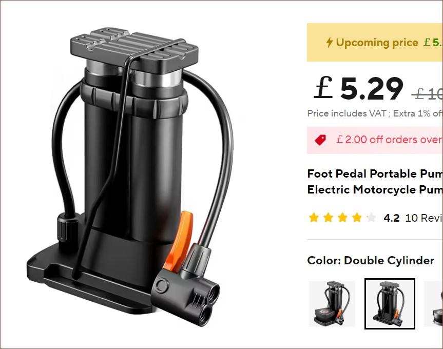
Yes. They're sold as foot pumps, typically £5 - 10 on AliExpress.
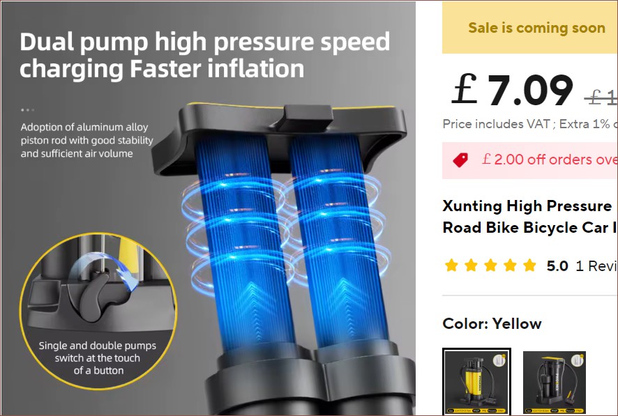
There's even one that has two pistons in one! Ok, ok, this strategy felt like a duct tape and cardboard idea when I initially proposed it but now it's making a lot of engineering sense! There's a Xunting-branded one for a £2 more that seems a bit higher quality and has a toggle for single and dual pumping (I believe it's to switch between high pressure/airflow pumping respectively):
This is likely the pump I'd pick.
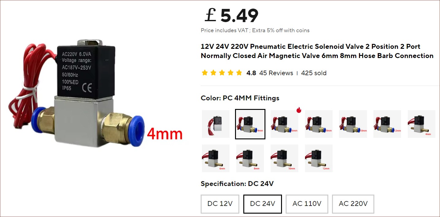
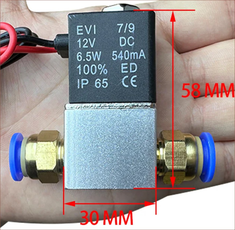
The repressuring valve seems lowcost and straightforward enough:
I guess the next question is how to accurately measure the outside air pressure. The cheapest way seems to have signal wires going outside through the same multicore wire as the mains coming in and have another barometer sensor out there. It's likely I'd need to anyway for things like the LED timer and outdoor VOC detection (so that the internal VOC has something to compare against).
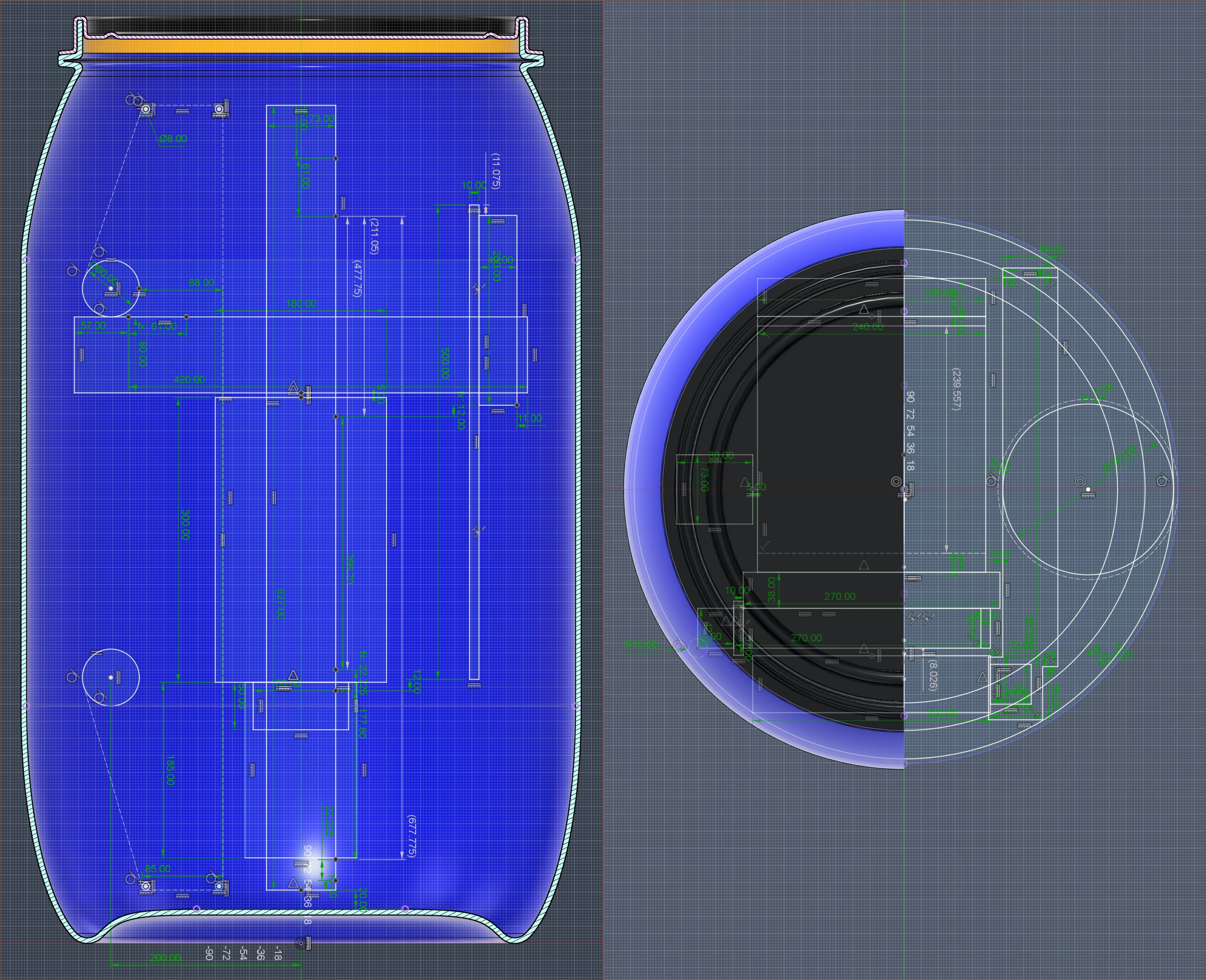
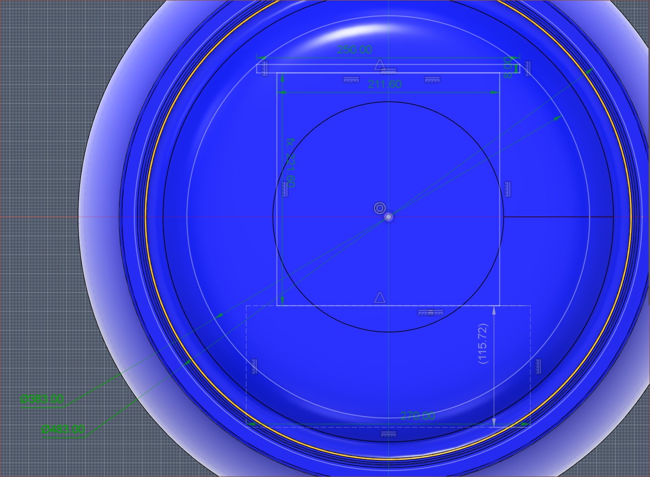
I've unintentionally put in upwards of 9-hour days for... checks notes... 7 days to get the above solution which achieves multiple desired goals. As you might understand, the first complication is that I need to work within a cylindrical area. The second is that it's not a pure cylinder but curves at the top/bottom similar to a filleted chamfer, meaning some things only fit at certain heights. If you look at the top-down angle above, that's the reason why there are 3 concentric circles to denote the perimeter of the barrel at its widest section, about an inch from the opening and the opening itself.
Printers I've seen, like the Ender 3, have the screen on the right side. Thus, that's why the print volume is more leftwards. I plan to have the screen on the inside and perhaps a status LED on the outside.
Most of the time was on the motion system. Considering that, unlike FFF, this application calls for very precise movements that don't need to be particularly fast, it's probably no surprise that most of my research was on ball screws. Considering my work on delta belt tensioners, I've decided that I'd rather not deal with belts and the design/manufacturing time that comes with it.
Day 1
One of the first things I saw was the below video:
Then I went on AliExpress to see different options and how much extra length is needed for an axis. The lowest I found was 119 - 120mm.
Day 2
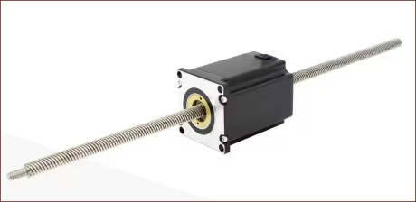
I found out about non-captive stepper motors:
I was also asking Gemini about some questions about the build plate material. Both it and I believe that a typical aluminium bed will interfere with the charged-plate responsible for attracting uncured resin back onto the film.
Then I found out about enclosed sliding tables, which look as sleek as the Windstorm S1 I mentioned a few logs back:
I thought this would be particularly useful for the Z axis. If kept in the orientation seen above, the build plate would be vertical and exhibit no counter-lever sagging, unlike the typical orientation for 3D printers having the build plate parallel with the ground. This was one of many reasons for keeping the barrel upright. However, this orientation risks resin falling onto the ballscrew. Hence, that's why I thought this enclosed module would be beneficial.
Then I found a forum post titled Ballscrew Basics where the OP mentioned some interesting things. notably:
"But what about accuracy?? Isn't that the primary reason to use a ballscrew?" True, accuracy can be extremely high, but ACME screws can be ground and with a correct, matching nut, can exhibit identical accuracy to the finest ballscrew.
This claim both tracks with the video above and the Prometheus MSLA designers testing both a lead and ball screw. One of the bigger factors is efficiency:
A typical ACME threadform has an efficiency of roughly 40%, whereas a ballscrew's efficiency can easily top 90%.
Hypothetically, wear is another one I've read in multiple different locations over the years, but in all my 8 years of scanning the entire internet for 3D printing information have I seen something along the lines of "my T8 lead nut wore down and I needed to replace it".
A specifically important part are the bearings though:
A C0 ballscrew is worthless if it is supported by a single, standard radial ball bearing.
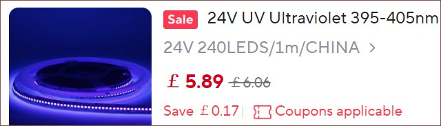
Moving on, I found this 201mm curing lamp but I'm likely just going to use a 240LED/m 405nm strip:
For 25cm, this strip is 3 - 4W.
Up until this point, I hadn't even really started to think about the cartridge situation. I had the great idea of
having each cartridge be 44.45mm tall (the same as 1U in a server cabinet)
a cam system such that the Y axis could select what cartridge is pressed onto the film-covered LCD,
designing a dynamic system such that trades Y print space for cartridges.
The X length of the LCD is a tad shorter than 3 cartridges, so the adjustment would essentially be a range of 2 - 4 LCD-lengths.
Thus, I could design so that the standard set of 4 cartridges allows for the full 470mm build depth, additional CMY allows for around 330mm and, if needed, another set of RGB cartridges for around 200mm.
To facilitate this, A way to easily swap between print beds of multiple lengths would be required.
Day 3
This was the day I found out how to get around the current AliExpress bug that it doesn't allow me to put stuff in the basket because of some "new user" discount when I'm signed in. I can add it into the basket via the wishlist.
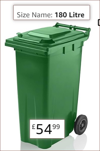
I was feeling the squish of the barrel and was wondering the potential to use a wheelie bin because they're large and rectangular and about a meter tall, which is needed for the Y axis:
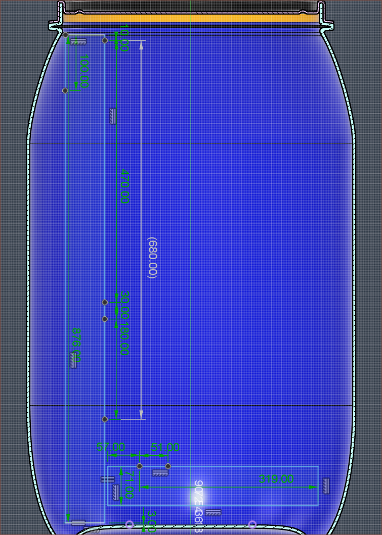
I finished this day having issues with fitting the 700mm axis as well as having space for the PET film:
700mm Y axis and 200mm Z axis
Day 4
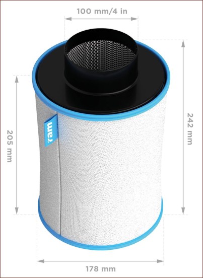
Considered going down to 600mm and aiming for 5 materials and 350mm Y, somewhat competing with the Prusa XL. Then I found out that the 4" part of 4" filters were only the opening and that the actual diameters of them are typically a tad less than 180mm:
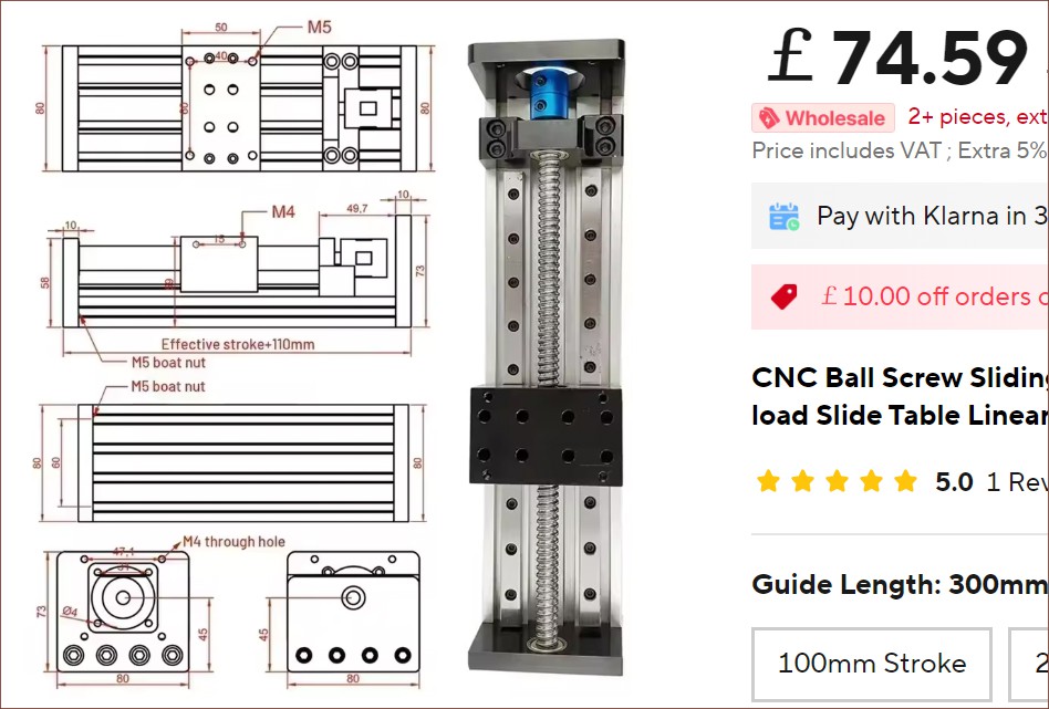
This was also when I considered using these 80mm wide, 2*MGN12C sliders for the Y:
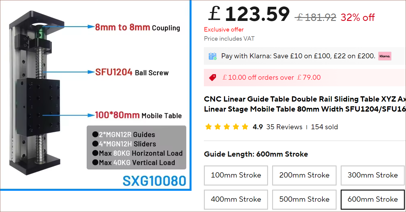
Later in the day, I found out that they also come in a 4*MGN12H configuration:
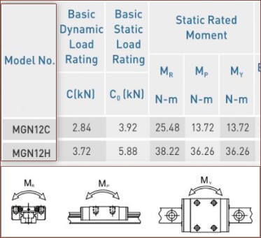
There are notable rated-load differences between the C and H versions of the carriages.
What I realised is that, in the sketch, I'm seeing the end-to-end stroke length, which didn't exceed 700mm. This is the effective stroke + the table length. For The 50*80 table, this means a 700mm axis is 750mm end-to-end. The printer only needs a minimum of 500mm or so to allow the scanner, curing LED strip and charge plate to sweep across the entire 470mm area. Thus, a 600mm axis with a 100*80 table could be used, saving the 50mm I needed to better fit the axis inside the barrel. The price didn't change that much from a 700mm 50*80 table.
I totalled up the length of the end effector and I got a whopping 271mm, with 102mm being the laser module and its linear axis. Yes, I'm going all the way with trying for these 3DPCBs. Probably 30% of this project has been "Will L^3 work?" and the other 70% has been "Will L^3 allow for multilayer PCBs and silkscreen?". I'm sure I've had this discussion in #SecSavr Soapalai [gd0146]; I try and remove "print PCBs" from the specifications list and it keeps coming back.
Day 5
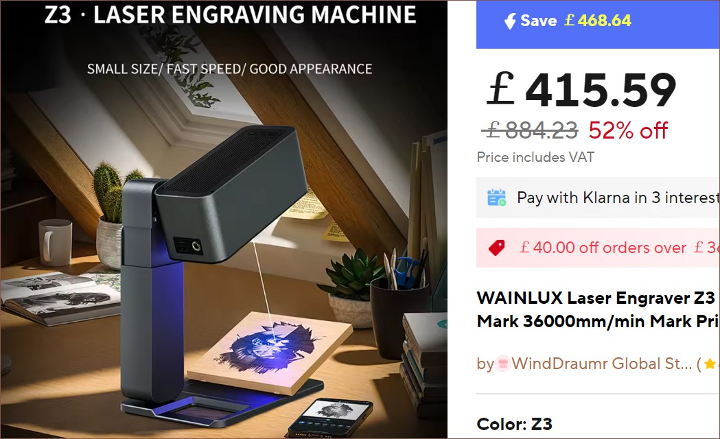
This day started by, once again, looking over laser module options (and so I did some updates to the laser module log). One cool one I found was a WAINLUX Z3, which has a 50um square spot with 4.5W of optical power and a workspace of 50*50mm for a little over £400:
Nice to know that there is at least some kind of option for an off-the-shelf galvo system if it turns out that the ballscrew movement is the speed bottleneck.
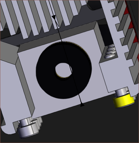
Along with the 0.04mm square spot and low cost, it seems ideal to use this because it seems that the included heatsink can be removed and a custom one designed if required.
Because of the large, activated carbon filter, I wondered if there would be enough space for the 50*80 slider, which wouldn't block getting things in/out of the barrel nor be in a position that risks resin getting on the components. Turns out a 300mm axis fits:
With this, the solution for fitting everything in this 220L barrel actually started to pass.
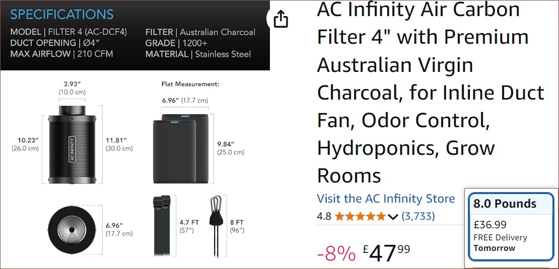
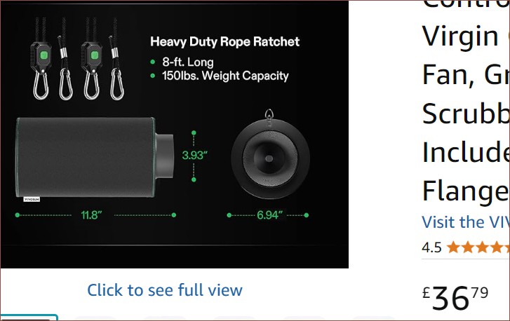
I looked around and it seems that the shortest possible filter is 200mm for its main area, or 250mm from edge to edge. Ac Infinity has the only refillable one I can find, and theirs is 260mm x 180mm with a 40mm opening:
This uses 4lb of charcoal per refill. The lowest value is an 8lb bag, thus £18.50 at most for a refill. Most basic filters start at £30, but you'd get a brand-new pre-filter and not have to manually fill up the filter. However, Vivosun is currently the cheapest filter I can find that has the same 1200+ Iodine Adsorption Value is only a few pennies cheaper than the 8lb refill bag:
Thus, it does seem like AC Infinity's offering is cost effective, especially since they give 2 pre-filters. Someone confirmed that they don't acid-wash the carbon, which will oxidise metal surfaces in minutes. I also looked into industrial filtration, and it seems that the only difference is that they use activated carbon pellets and the fans are obviously larger than this 26dB one I found the following day:
For context, a 220L volume is about 8 cubic feet.
Day 6
I found this repair video that is essentially a teardown of the NEJE laser module:
2 pins are for the diode and the other two are for the temperature sensor.
I determined that the best solution is to have a single MGN12C table mounted behind the 38mm screen module and mount the laser such that it shines through a 5mm gap, as the charge plate, CIS and LED strip are all relatively thin. One solution could be to trim the heatsink by 15mm:
Realistically, the main concern is to make sure that the laser is not in focus when going through the PET film, which has the potential for a stray particulate to stick onto it, potentially vaporising and poking a hole in the film.
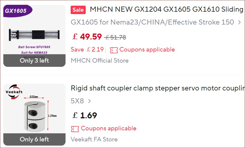
I spent quite a lot of time wondering if I should use SFU1610 and a 0.9-degree Nema17 to get the same effective resolution, but then I found out that 0.9-degree Nema 23 steppers indeed exist and so I'm sticking with SFU1605 for all axes.
150mm stroke fits, which I believe is good. The full Y axis length can be used for a PCB, unlike my earlier assumption a few weeks ago thinking that it would be 1 LCD-length short. I'm trying to compete with JLCPCB so it should be fine as long as the laser axis is at least over 100mm. With 148*470mm, an entire 100% keyboard PCB could be printed. That's a good size for mechanical keyboard hobbyists 😏.
Day 7
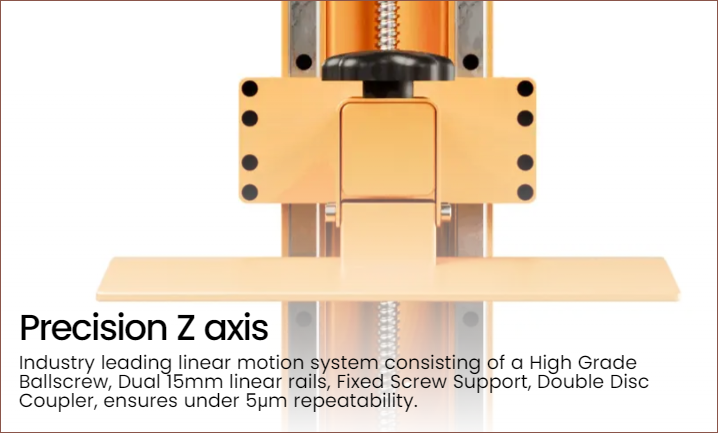
I stumbled upon the Athena II which is also using the new 16K 9.55" panel. One thing I noticed was their mention of "double disc coupler" for the Z axis:
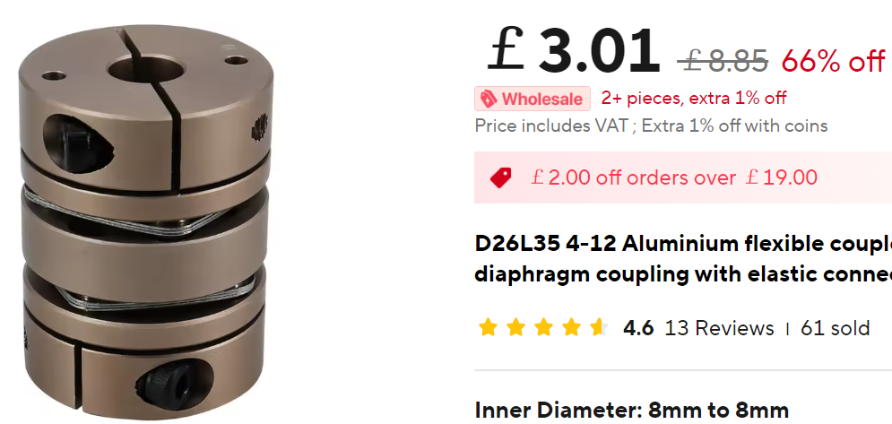
This lead me to this rather nice looking "diaphragm coupling":
I can only assume that they're to allow axial flexibility while ensuring radial stiffness. The majority of linear tables (even the more expensive ones) seem to use a basic, rigid coupler.
I was also looking at the pros and cons of 0.9-degree steppers. It'll merely add £30 tops to the costs but its usefulness is questionable, thus I'm sticking with standard 1.8-degree for now.
For the PET, I considered taking advantage of gravity and using mass-based tension. It won't be as dynamic as dual motors, but it's an option if I'm limited by the amount of steppers. This solution already eliminates quite a lot of steppers needed compared to the very first design in 2022, such as the dual steppers for selecting the cartridge on the left/right of the machine.
Day 8 / Conclusion
So, finally, I can answer the simple yes/no on some of the questions I raised in the previous log, mainly that the solution I want can be contained in a 220L barrel. Yes, it did feel odd (and a bit disheartening) to start solving at like 0900 but the time suddenly be 1900 some days. Even at the typically-£70 cost of a barrel, I don't think someone could DIY a cheaper enclosure, especially one that's airtight and UN certified for hazardous chemicals.
I should be able to get 211*470*215mm XYZ build volume with laser diode and air filtration, assuming that the Halot-X1 module is approximately the dimensions I've estimated and I can make 1U-thick cartridges. Those cartridges might have a built-in or detachable handle, and there is the potential ability to fit 4 - 10 materials
The laser, 3 linear axes, 2 Nema23 motors and UV LED come to £300. The filter and fan is probably another £75. The screen alone is around £120, the current lowest barrel price is £55, scanner sensor and wire maybe £25, PET £10, a 5-pack of Nema17s is £35, two TMC5160s is another £25... let's just say the minimum bound is £700.
I just found out that Creality just uploaded a rather interesting video about replacing the UV light board:
I have a feeling a lot of good information is in here. It's basically a teardown video of their moving display module. Unlike other MSLA printers, this one is designed to move, and thus it's the most compact solution I've ever seen:
The LCD assembly with the protective cover removed. The technician is holding onto the "heat sink base plate".
And, as mentioned in previous logs,
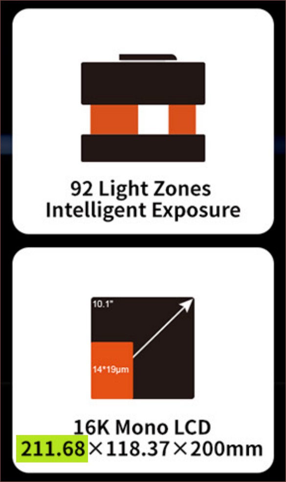
the backlight has local-dimming zones for higher longevity / lower power consumption and
the screen is both
approximately the same width as A4 scanner sensors (the minimum for the X axis, for where an A3 is the maximum) and
extremely high resolution, so it's more future-resistant (though unfortunately with 3:4 pixels instead of 1:1 square).
Thus, this solution feels star-aligning. The local dimming is the best part, because the whole screen wouldn't be exposed to UV when only a small section needs to be, which is a case that's even more likely with the SlimeSaver than a typical MSLA. I don't think even Creality knows just how long it will last though because no numbers have been reported.
The Y dimension of the panel is 118.37mm, so it makes the most sense for the Y axis to be 4 times that at 473.48mm since it's rather close to the 480mm I was considering. Maybe some overlap would be required and it would be closer to 472mm.
So, what's inside?
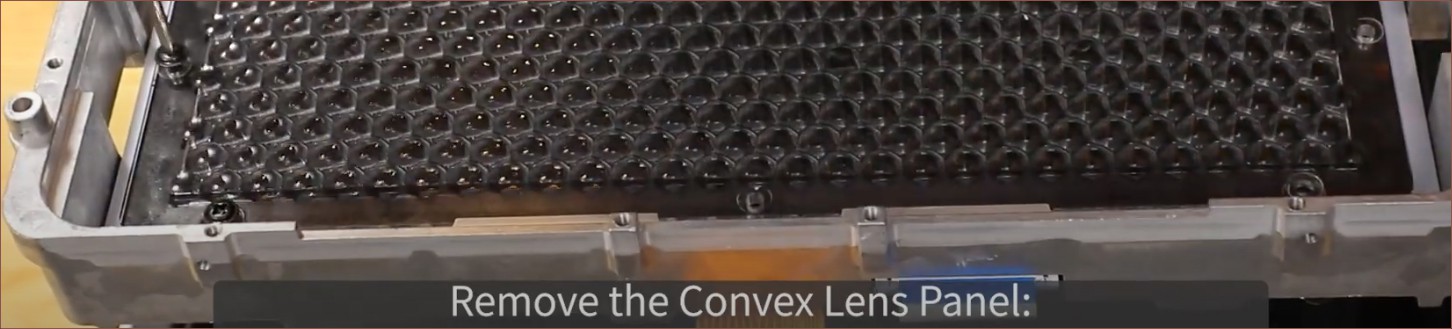
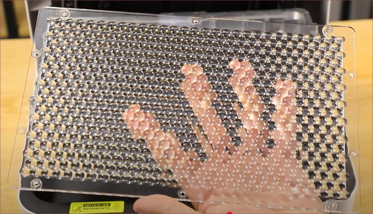
The first thing I noticed was that they're using much more LEDs for the light source than usual. I counted 19x28/9pcs on the mesh grid under the lenses to block LED light from straying away. There's only 92 dimming zones, so there is likely some electronic reason why the engineers couldn't've done 542 zones. The product page claims 6.5 mW/cm2, which is more than double that of the Anycubic Mono 4.
The lens array looks cool. This could've been the kind of backlight resolution if every LED was individually addressable.Hexagonal mesh. It looks rubbery but it's solid.
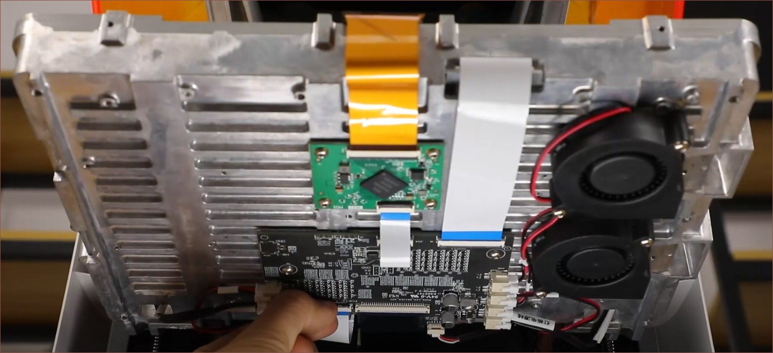
I'm also starting to notice that more printer manufacturers are starting to incorporate cast metal (aluminium perhaps?) into their products:
I believe it's also used as a bit of a heatsink as there are fins in it. There are also two blower fans; could they be curving around, or are they to exhaust the warm air? The product page suggests that they use the heat energy to warm up the enclosure.
That orange cable goes to the LCD. Interesting that the signal goes through 2 different boards, with the input being notably smaller. Perhaps it's something like eDP or HDMI that is then converted to MIPI for the screen?
Seems that the LEDs run on 24V and there are 2 ports on opposing sides. Perhaps the electrical path goes through one and out the other? Maybe each port controls half the board? this is an aluminium-backed board, so Creality is likely limited to a single layer, though I do wonder if any of those larger resistors are 0 ohms to jump over tracks. The board is certainly a lot fancier than what I had in mind, which may allude to the reason why it says V21 on the bottom.
There also seems to be some copper (heatpipe?) rows that leave and go somewhere:
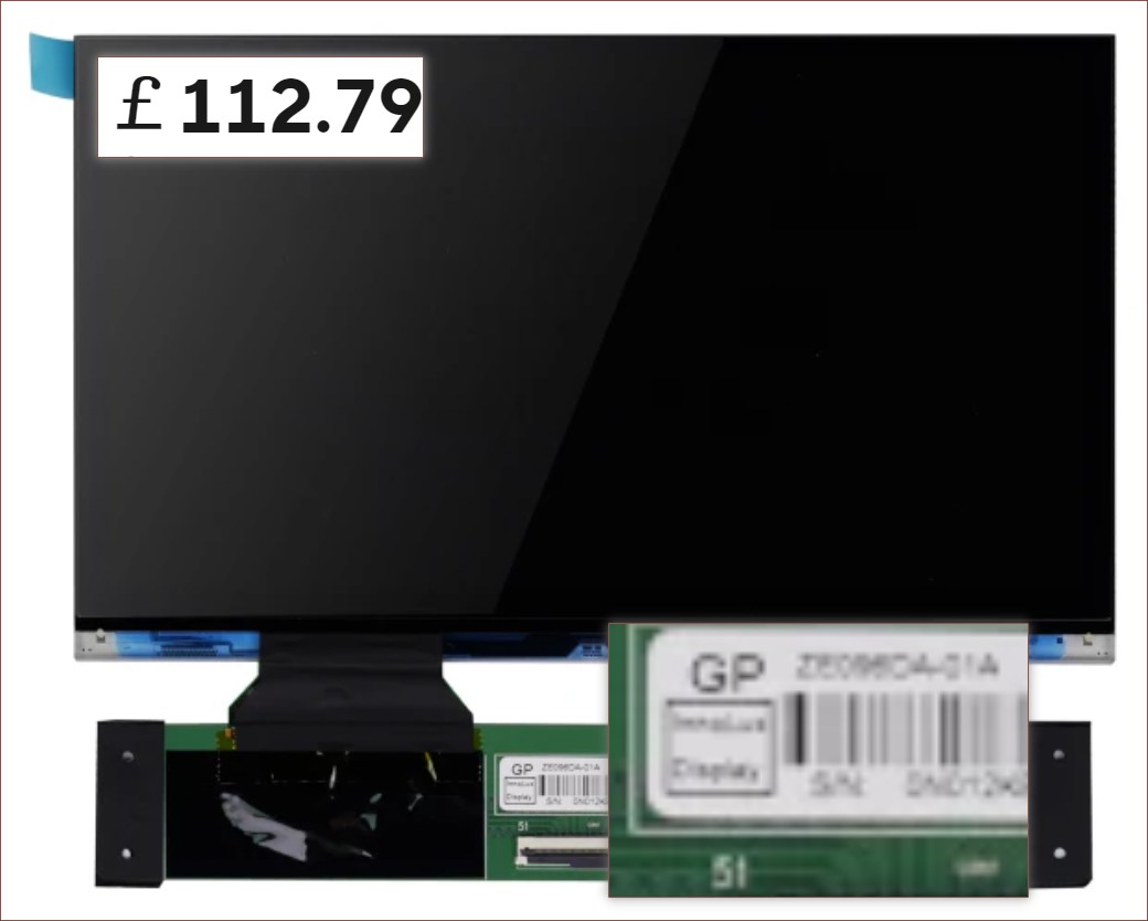
At least this angle allows for a better look at the control panel. The 4 fan ports are obvious, but all the tables are unfortunately a bit more cryptic to me. I think, like with the Q8100-60002 scanner sensor I... still haven't talked about on Hackaday (whoops), the table is just referring to the names of each of the components in the densely packed sections. Is there some kind of regulatory or debug requirement to put each and every component name on the silkscreen? There's also some TX/RX pins; are they for a chip on the other side of the board or exposed from the input ribbon cable?I punched in "ze096da-01a" and one promising result I got was the YI2410A0-1:I presume that the dyed polarizer is to further improve LCD longevity? I remember seeing a screen with this tint for a 385nm printer...
Ah. Okay. Interesting that it's the same specs other than it's advertised as 9.6 inches not 10.1. It even has the same 211 x 118mm build dimensions. I just did the calculation with the "visible area" specification and got 9.548 inches diagonal. So why does the LCD manufacturer claim 10.1 and UniFormation round up to 9.6? Maybe nobody bothered to check and it's just trickled all the way through?
It's convenient though that the lower 19um resolution is on the Y axis, because it may be possible to pixel shift by 9.5um to get even higher resolution. It's likely entirely unnecessary though since the pixel size is well below the 35um satisfaction threshold.
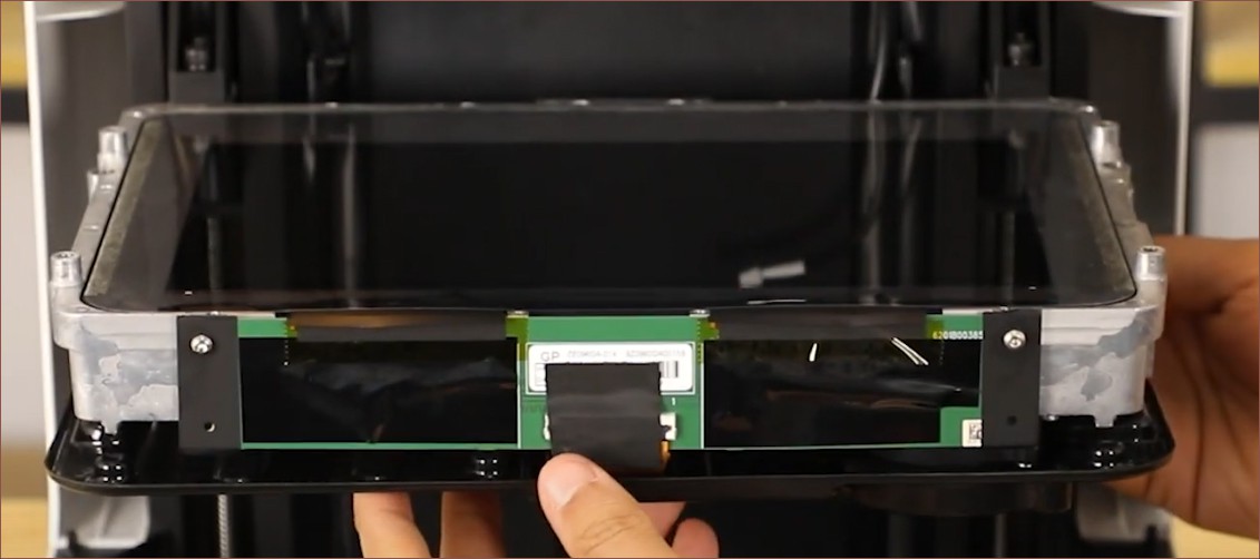
Anyway, in the Screen Replacement video, it seems that the screen used in the Halot X1 is surprisingly opaque when off:
Bottom sideTop sideFront sideThe thickness of the entire stackup is barely more than the height of the LCD PCB and its width is about the same as its active area. My pixel estimation of the width and nominal thickness is 268mm and 38mm respectively, with the fans sticking out another 10mm or so.
If I zoom in on the panel for the Saturn 4 Ultra, it seems that the codes match up and it's the same exact screen:
As alluded to in the conclusion of a recent Coaxial8or log, I'm currently wondering if it makes more sense to spend the time and money designing SlimeSaver parts that are printed via SLS or MJF services. I'm not living in 2018 when such services were rare and expensive. The benefits would be more design freedom, higher durability end-use parts, a BOM that doesn't rely on the builder already having a 3D printer and myself not being further delayed working on FFF -- a technology I still believe is ""legacy"" the same way any recent PC won't boot from a HDD but still good as an external storage medium.
The main concern is being slowed down by checking over CAD files multiple times to ensure they're good enough to be printed.
Pivot (back to) to 210mm, non-motorised X axis?
Understandably, I still want a printer that is large enough for me to print the #T^2 Tiles [gd0095] (192mm?) and #Teti [gd0022] (205mm??) and other than the Y axis being in the 400 - 500mm range, my justification for going larger just seems kind of weak at the moment .
On the flip side, there are 3 notable complications I'd avoid.
First would be engineering/programming/testing a slider. I know there's still the laser slider that needs more or less the same things, but every little helps.
Secondly would be getting the 4-segment intersections to line up. The shortlisted pixel sizes are merely 0.04mm and smaller, and it's probably already going to be an interesting thing to get entire rows to line up. XY tiling is likely an unnecessary complexity.
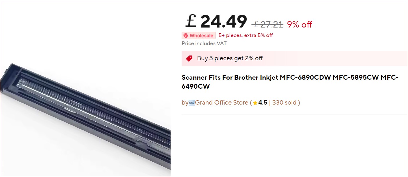
Thirdly would be the CIS scanner sensor. A while back I found a sensor for "MFC-6890CDW MFC-5895CW MFC-6490CW" that is 291mm wide but, as you might expect, there are many more A4 sensors to choose from.
Did they put the same scanner in both an A3 and A4 printer?What's extremely convenient is that the Halot X1's 10.1" screen is 211mm, meaning that the print area and scanner will be very well matched. The SlimeSaver doesn't necessarily need to use the 16K screen, but it would help massively for longevity to use its local-dimming backlight, negating the higher price of screen replacement. I think I've mentioned this in a previous log, but users are seemingly happy with the quality at 35 microns, meaning that the screen chosen needs to be 6048 pixels wide.
While researching prices (around £95 - 115+ on AliExpress), I found out that the Saturn 4 Ultra has the same screen, as well as 8G of RAM. The Saturn 3 is mentioned to use Linux whereas the 4 is a "self-developed system". Could it be possible to hack a Saturn mainboard instead of buying a £130 NanoDLP computer and £30+ HDMI driver board?
The minimum Z height target should be slightly longer than X to be able to print something cylindrical with supports.
Pivot to 150L barrel and/or place on its side?
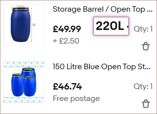
Me remembering about the 150L barrel is partially what spurred me to consider the smaller build volume above. It's a slightly shorter, slightly rarer and notably narrower version of the 220L barrel:
I'm wondering if it's a better user experience to fit such a barrel under a bed and get to the print like opening a drawer. I've also got concerns on gravitational forces exerted on the print itself during printing, but I don't really have any concrete evidence.
220L barrels do seem a lot more common though, and now I've even found an ebay listing for a 220L for merely ~£5 difference. Therefore, the real question is if the 90mm smaller diameter is enough of a difference.
The new 211mm print volume should fit in the 150L, which has a diameter not too far off from the 220L opening (orange ring).
I guess it depends on factors like:
if the entire printer cylinder needs to be able to come out of the barrel.
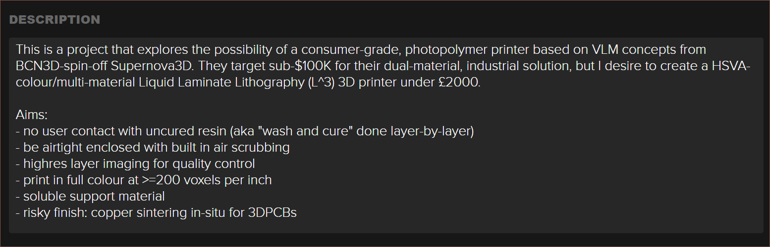
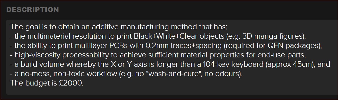
So, 3 years after the start of this project, I've finally simplified the project description:
Description before the changeDescription after the change, which sounds quite a bit like the #SecSavr Soapalai [gd0146] . Surprisingly, this took over an hour to write.
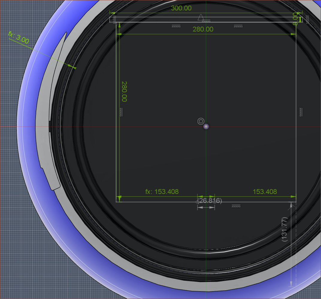
One of the points is the build volume. I've been sketching some rough measurements and I believe that 28 * 48 * 28cm (XYZ) is a reasonable goal to aim for.
Image showing the XZ build area, the 7" screen overlap of 27mm, and the 3mm gap between the 8mm build plate and the barrel neck. The expected height available for the screen and light sources is 131mm.
This build volume is similar to a CR-10 (and its clones), but the Z axis isn't the longest. If anything, the Z axis will be the shortest if additional space is needed for internal components. Part of the reason is due to the shape of the barrel, but it's mainly so that the slowest axis isn't also the longest axis, which is usually the case in the MSLA industry.
The X axis is limited by the fact that PET cake collars max out at 30cm wide. It sounded reasonable to use a 30 * 50cm build plate and have the XY build area be a 1cm margin within, hence 28 * 48cm. Due to BambuLab, it's also wise that the X is at least 25.6cm so that Makerworld models fit. To allow for the printing of vases and other large, cylindrical objects, it would be ideal if the Z axis matched the X, hence a height goal of 28cm.
I expect the laser-accessible Y length will be around 10cm shorter. An area of 28 * 38cm is still plenty for PCBs, especially if they're printed such that the thin side is against the plate like standing dominoes.
PLA-based composites with 90% and 80% (wt.%) copper loading [with] a 5.5-W 450-nm blue laser with various combinations of parameters to “sinter” the surface of the samples. [...] The copper particles became oxidized during the process, and none of the samples yielded a conductive result.
Instead of partial melting, sintering (i.e., bridging adjacent particles) can be achieved by chemical reaction that causes deposition of a native copper layer on copper particles [...] using copper formate, which [...] spontaneously decomposes at approximately 200 °C to form native copper and volatile compounds. [...] However, copper formate, formic acid, and ethylene glycol are all incompatible with the temperatures associated with FDM printing (200–250 °C).
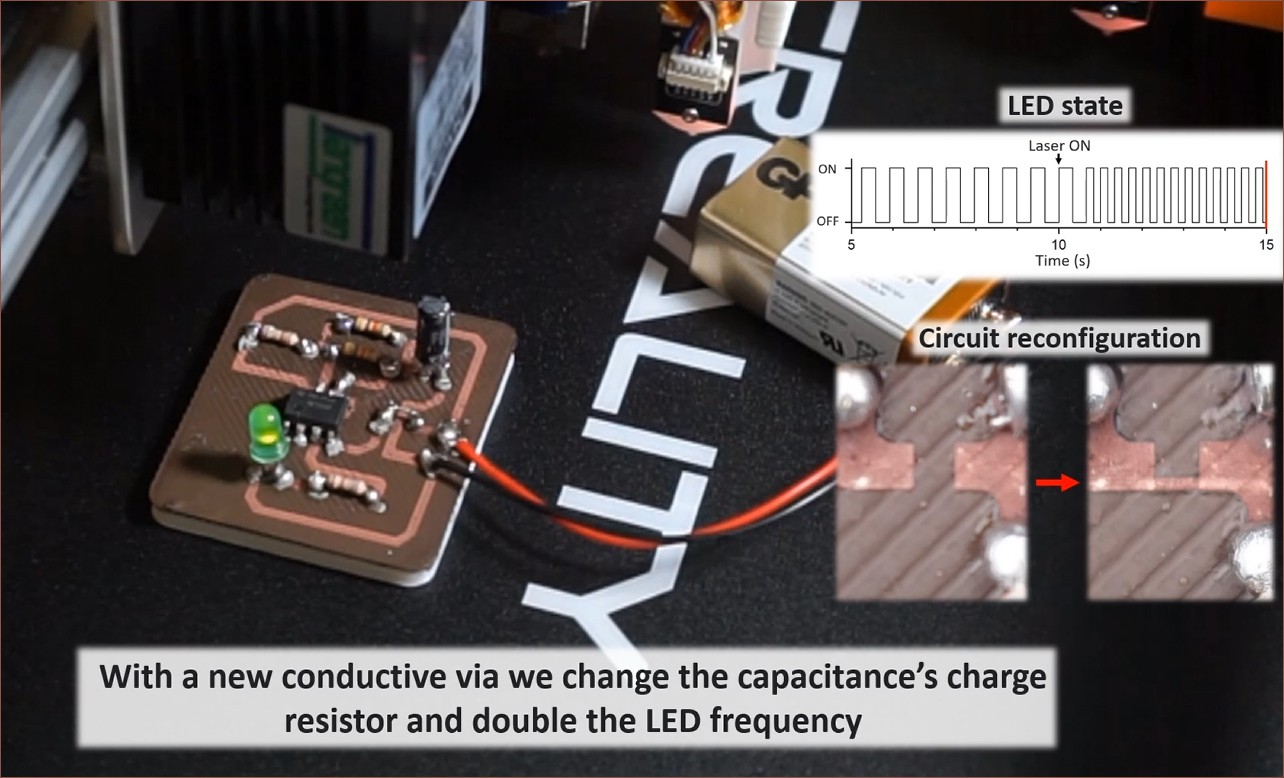
They reported a resistivity of 400 μΩ cm and included a video showing a 5.5W blue laser adding a new trace to a printed, active circuit:
Finding loads more papers
Because I don't have the limitation of FDM, and my hypothesis of sintering particles suspended in matrix possibly disproven, I started looking into what the aforementioned paper was talking about when they mentioned native copper formation.
It seems that it's possible to use a laser to "reduce" copper (oxide) nanoparticles to copper at a temperature low enough to apply circuits onto PET, for example. General reading gives the impression that copper oxide nanoparticles are more stable than copper nanoparticles.
"There are two types of copper oxides: CuO and Cu2O. The band gap of CuO (∼1.2 eV) is lower than that of Cu2O (∼2.1 eV). Hence, Cu2O is reported to have a high transparency with a slightly yellowish color and usually absorbs wavelengths below 600 nm, while CuO strongly absorbs the whole visible spectrum range and is black in appearance."
So it sounds like a 450nm laser should be fine. I expect all the researchers are using lasers that their uni had on hand, and high powered blue lasers are relatively new.
"The cupric oxide (CuO) nanoparticles are air stable, cheap, and easily available materials; they are also good precursors for fabrication of Cu micro/nanostructures by using selective laser reduction."
So I guess this is why they're common in academia.
 kelvinA

 As any 21st century kid would, I coded this whole thing in one monolith in about 2 hours to then get a lot of "VHDL says no" type errors for another 3 and a half to finally reach the plateau of productivity. Last was polishing everything in another 4 hours. I feel like things would've been even longer if I didn't start programming with easy-to-read variable names: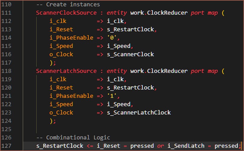

 The dimensions are allegedly 500mm on the base, 660mm at the top and 940mm tall. It certainly looks like a more-ideal spread of those litres in terms of fitting components inside, and my opinion is that the light grey does look particularly home-like. Looking at the levels, the light grey is also even more reflective of blue than the blue barrel.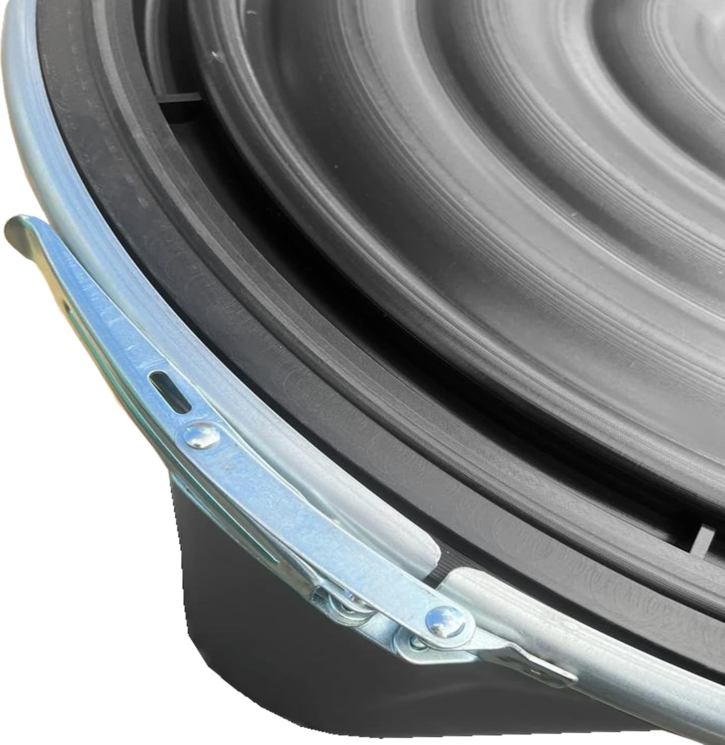


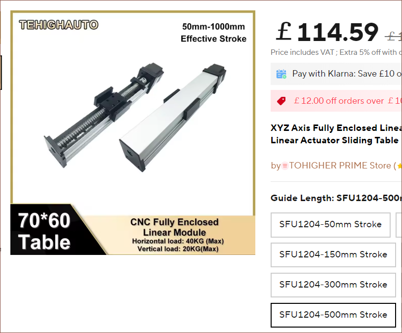 I thought this would be particularly useful for the Z axis. If kept in the orientation seen above, the build plate would be vertical and exhibit no counter-lever sagging, unlike the typical orientation for 3D printers having the build plate parallel with the ground. This was one of many reasons for keeping the barrel upright. However, this orientation risks resin falling onto the ballscrew. Hence, that's why I thought this enclosed module would be beneficial.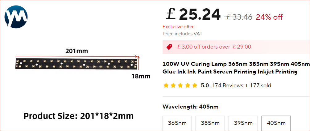
 Along with the 0.04mm square spot and low cost, it seems ideal to use this because it seems that the included heatsink can be removed and a custom one designed if required.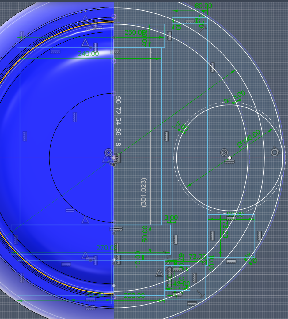
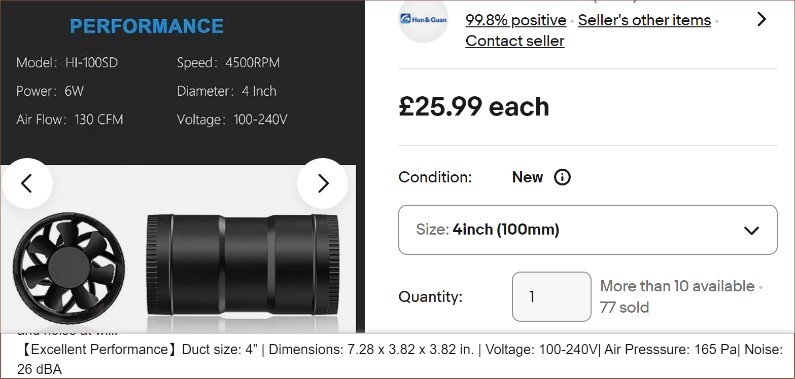 For context, a 220L volume is about 8 cubic feet.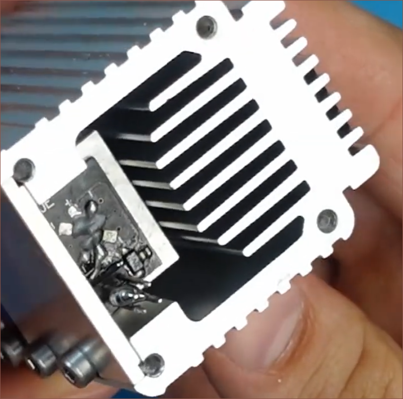
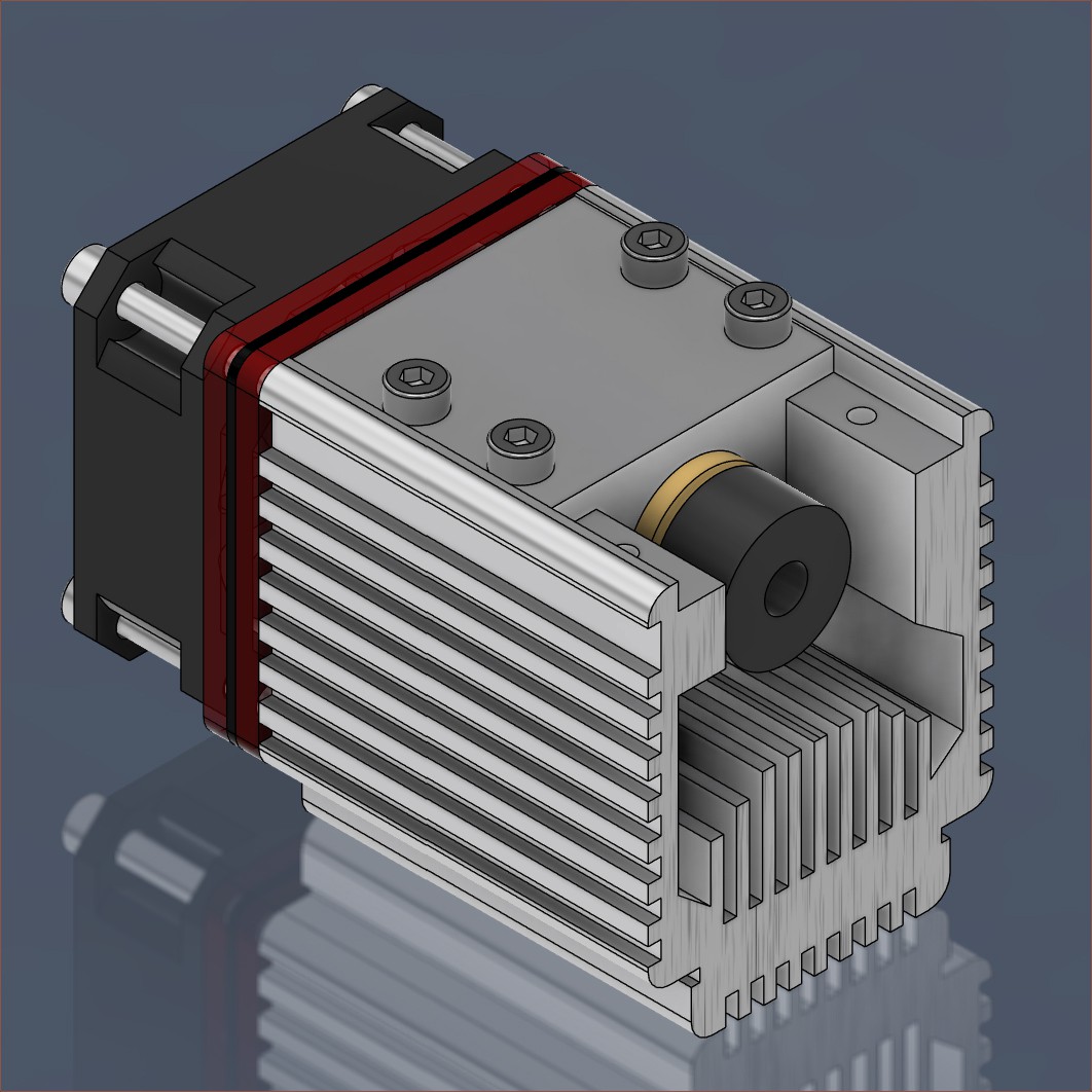 Realistically, the main concern is to make sure that the laser is not in focus when going through the PET film, which has the potential for a stray particulate to stick onto it, potentially vaporising and poking a hole in the film.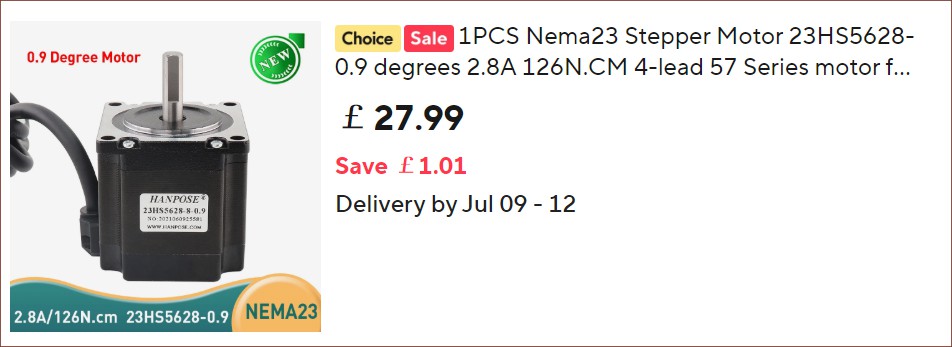

 I believe it's also used as a bit of a heatsink as there are fins in it. There are also two blower fans; could they be curving around, or are they to exhaust the warm air? The product page suggests that they use the heat energy to warm up the enclosure.
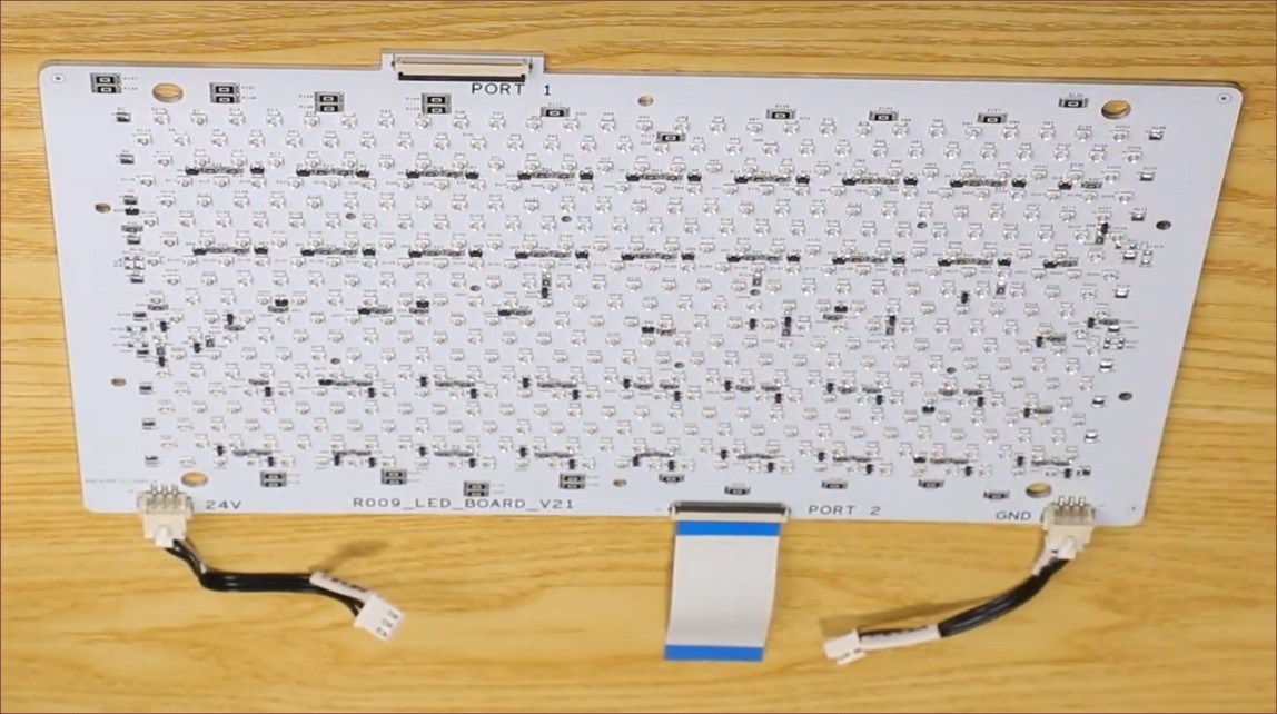 Seems that the LEDs run on 24V and there are 2 ports on opposing sides. Perhaps the electrical path goes through one and out the other? Maybe each port controls half the board? this is an aluminium-backed board, so Creality is likely limited to a single layer, though I do wonder if any of those larger resistors are 0 ohms to jump over tracks. The board is certainly a lot fancier than what I had in mind, which may allude to the reason why it says V21 on the bottom.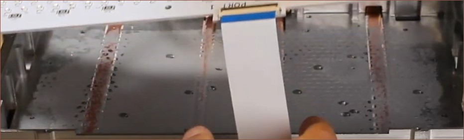
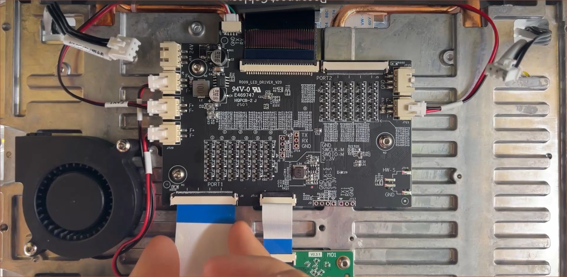 At least this angle allows for a better look at the control panel. The 4 fan ports are obvious, but all the tables are unfortunately a bit more cryptic to me. I think, like with the Q8100-60002 scanner sensor I... still haven't talked about on Hackaday (whoops), the table is just referring to the names of each of the components in the densely packed sections. Is there some kind of regulatory or debug requirement to put each and every component name on the silkscreen? There's also some TX/RX pins; are they for a chip on the other side of the board or exposed from the input ribbon cable?
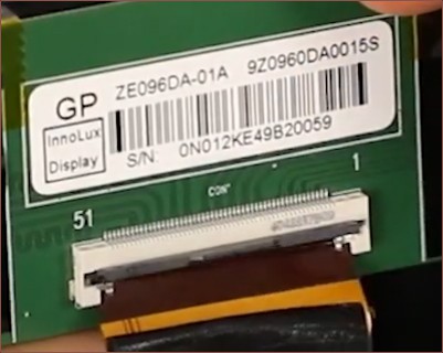 I punched in "ze096da-01a" and one promising result I got was the YI2410A0-1:
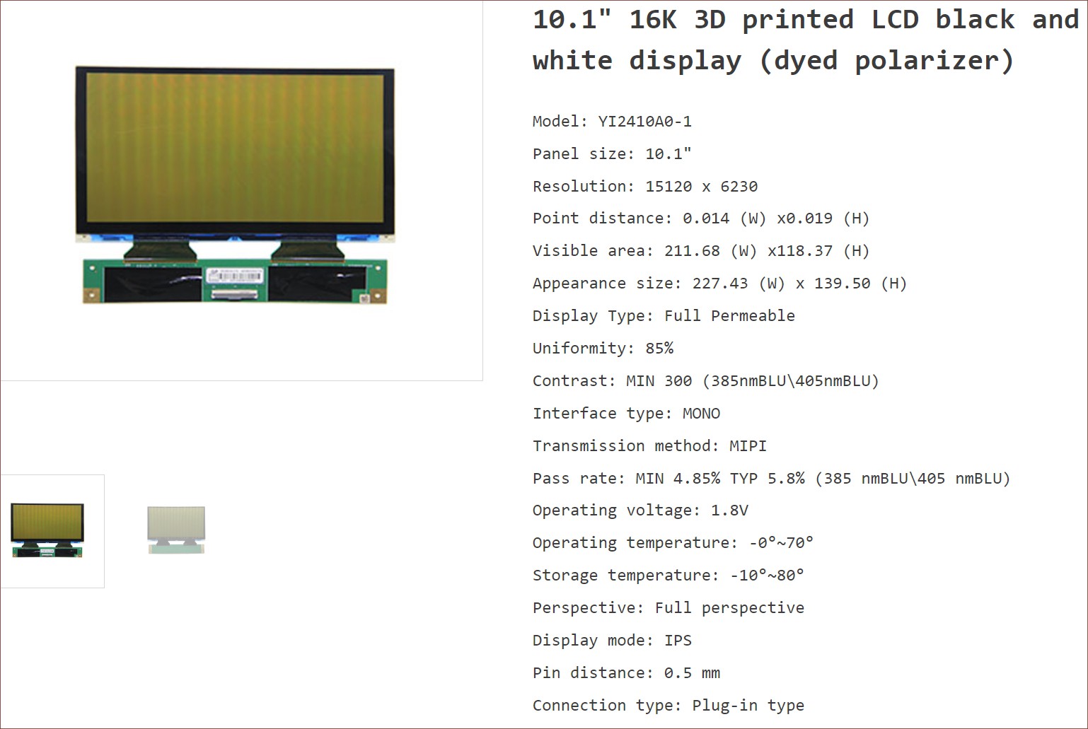 I presume that the dyed polarizer is to further improve LCD longevity? I remember seeing a screen with this tint for a 385nm printer...
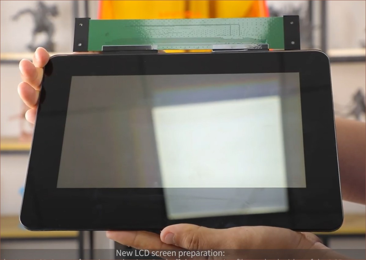
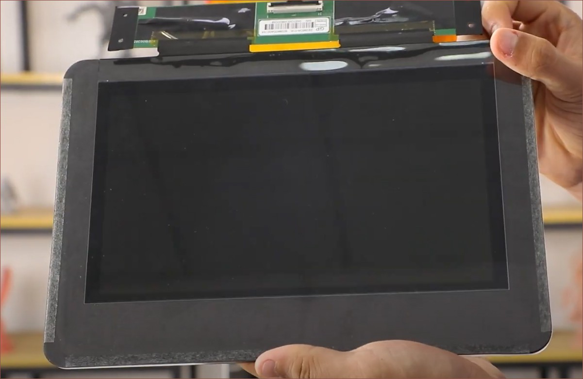
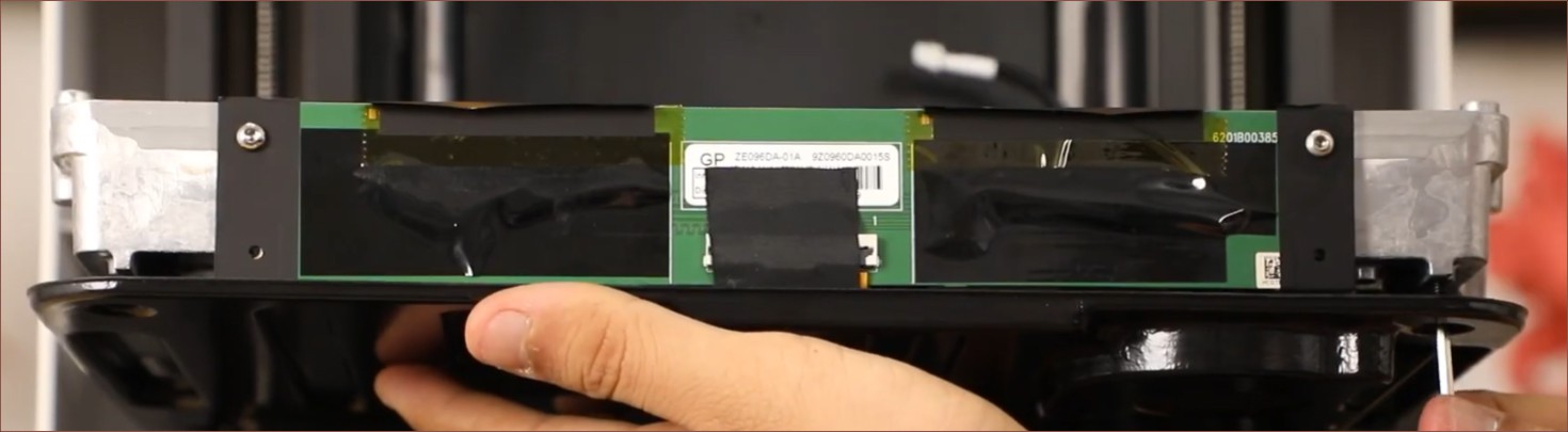

 What's extremely convenient is that the Halot X1's 10.1" screen is 211mm, meaning that the print area and scanner will be very well matched. The SlimeSaver doesn't necessarily need to use the 16K screen, but it would help massively for longevity to use its local-dimming backlight, negating the higher price of screen replacement. I think I've mentioned this in a previous log, but users are seemingly happy with the quality at 35 microns, meaning that the screen chosen needs to be 6048 pixels wide.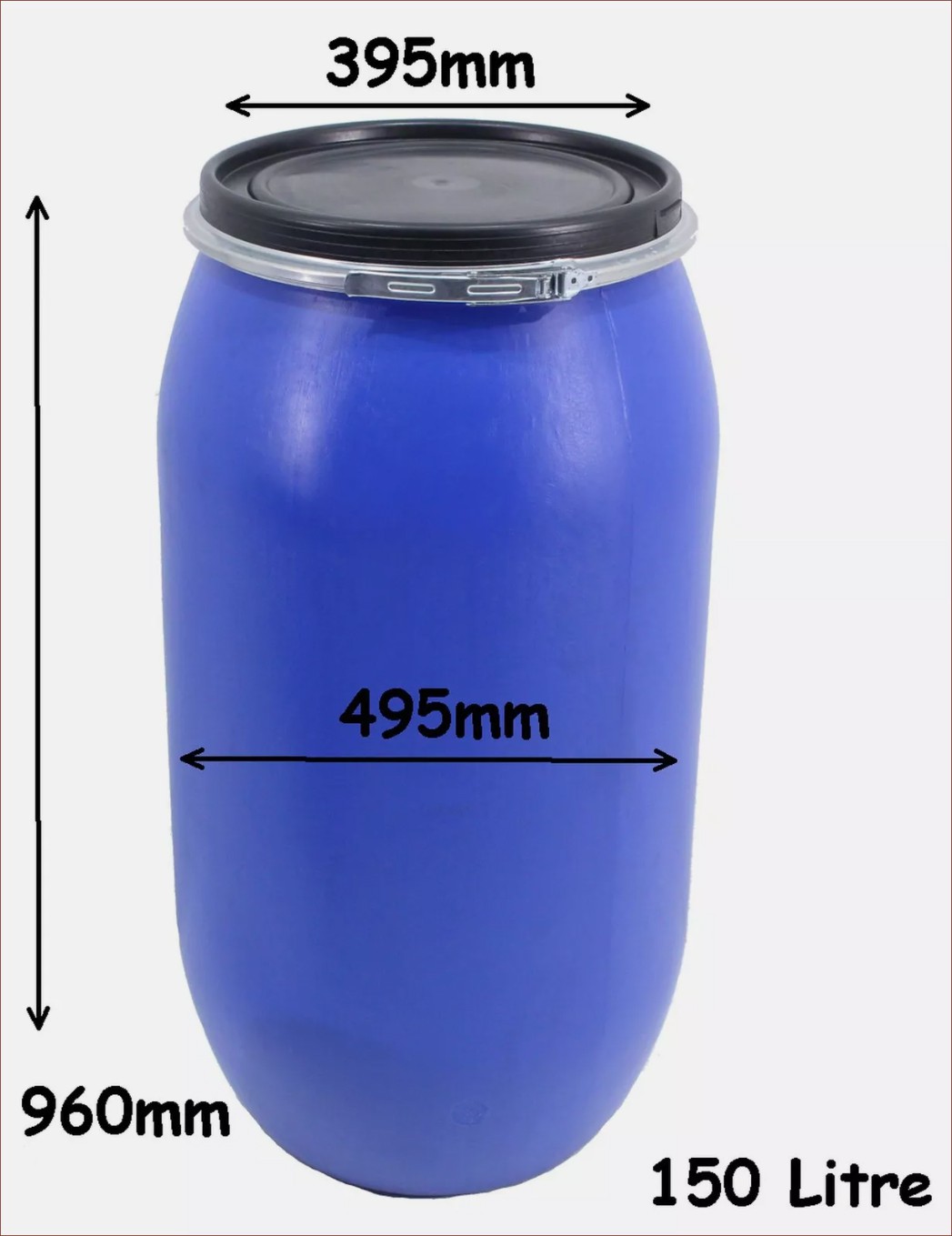
 Finding loads more papers