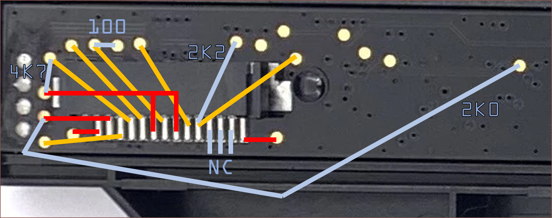
[19 Feb 2023, 12:00] I've spent the past 70 minutes finding continuity between the cable holder and the test pads, as well as any <100K resistances:

This sounds like there's some vague agreement with this reverse engineering research on a much more expensive sensor. I think this sensor is used for monochrome scans so the RGB pins might just not be connected. Though, I'd still expect 1 of the 3 pins to have continuity as LED input power. Most pins outside the ones shown above are 20 - 40 MOhms and the NC has no continuity with any I could find.
Those 4 silver pins arranged in a vertical line are coated with some kind of thin transparent material that prevents conductivity. There are traces going to them, so perhaps this is where my mystery NC pins are going to and they just don't have their own test pads.
The only thing I could guess so far is that pins 6 and 8 are ground.
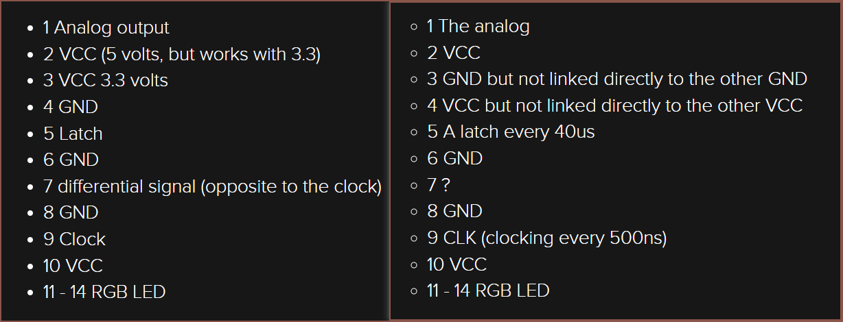
[13:50] I've found some more information in the instructions page of the aformentioned research. The project log one is on the left and the instruction page on is on the right.
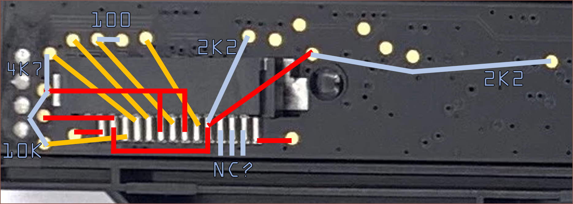
 I didn't notice this the first time round, but pin 2 and 10 are apparently connected and I can confirm this. The updated map:
 I'm not really sure what's happening with Pin3, so I'm going to assume the left one is the more up-to-date pinout research.
 kelvinA
Discussions
Become a Hackaday.io Member
Create an account to leave a comment. Already have an account? Log In.