 kelvinA
Introduction
I was supposed to write up this content eons back, but with the barrel literally taking months to model (a.k.a 1 day of progress every couple of weeks), I thought I'd at least get my 3rd and 4th Year projects written to Hackaday. Both projects were related to SlimeSaver, with more emphasis in 4th Year.

As you might be able to discern from the title of the report, the overall aim of my project was to create something like a robot vacuum but for gum on the pavements. Gum is the only thing that doesn't simply get swept away like other litter, but even a thumbnail is sufficient to scrape them off:

I had put together the BOM and how each component connects together:
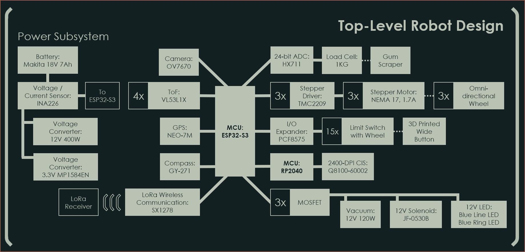
The idea was to use blue LEDs for ground illumination since pavement is primarily grey or brick while gum is white, thus blue would have the highest contrast.
Anyway, I'd like to direct your attention to one component in particular: The Q8100-60002 Contact Image Sensor.

Yes! This was all a way to inflate the real research question: Can this CIS be reverse engineered? It's both the lowest cost and highest resolution A4 sensor I've been able to find on AliExpress, even over a year after I submitted this report.
Unfortunately the answer is "No" at the moment.
The Experiment
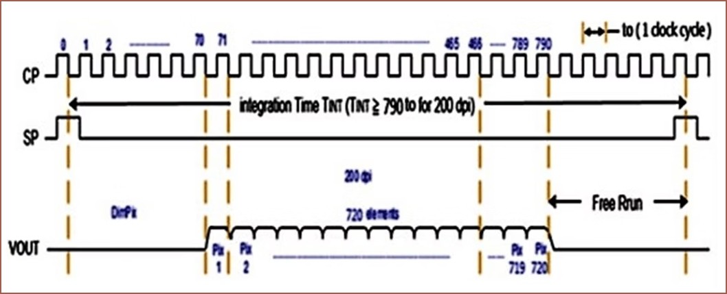
I only wrote 4 sentences about it in the report, but I had found a datasheet on the AMIS-722402 and wrote about it in an earlier log. I also saw that the M168 Module followed a similar signal pattern:
Now, since I was already doing VHDL for another module and I didn't want to learn yet another new thing, I used the De1-SoC FPGA to generate the signals I needed including a way to set the clock speed. The simulation from Quartus can be seen below:
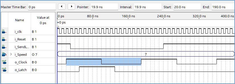
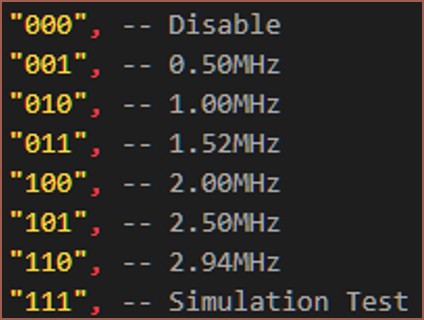 As any 21st century kid would, I coded this whole thing in one monolith in about 2 hours to then get a lot of "VHDL says no" type errors for another 3 and a half to finally reach the plateau of productivity. Last was polishing everything in another 4 hours. I feel like things would've been even longer if I didn't start programming with easy-to-read variable names: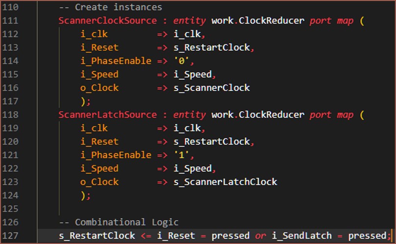
Next, I connected the circuit I needed on breadboard and tested to make sure the voltage divider got 0.3V on the VREF pin:
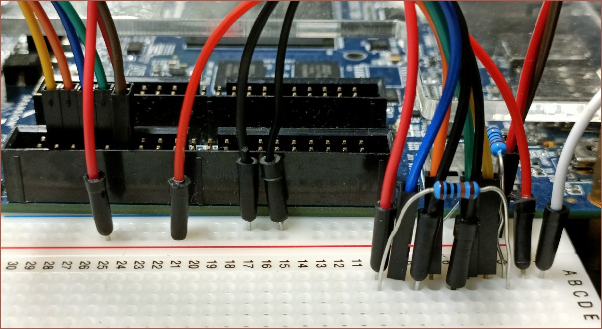
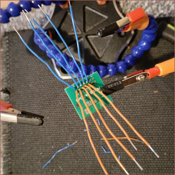
So after I confirmed the clock signals worked IRL and things, I plugged the sensor in and the green square is the only section I got an output from:
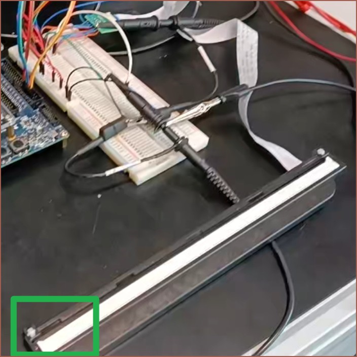
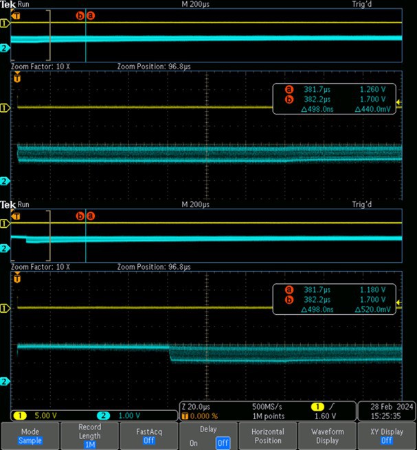
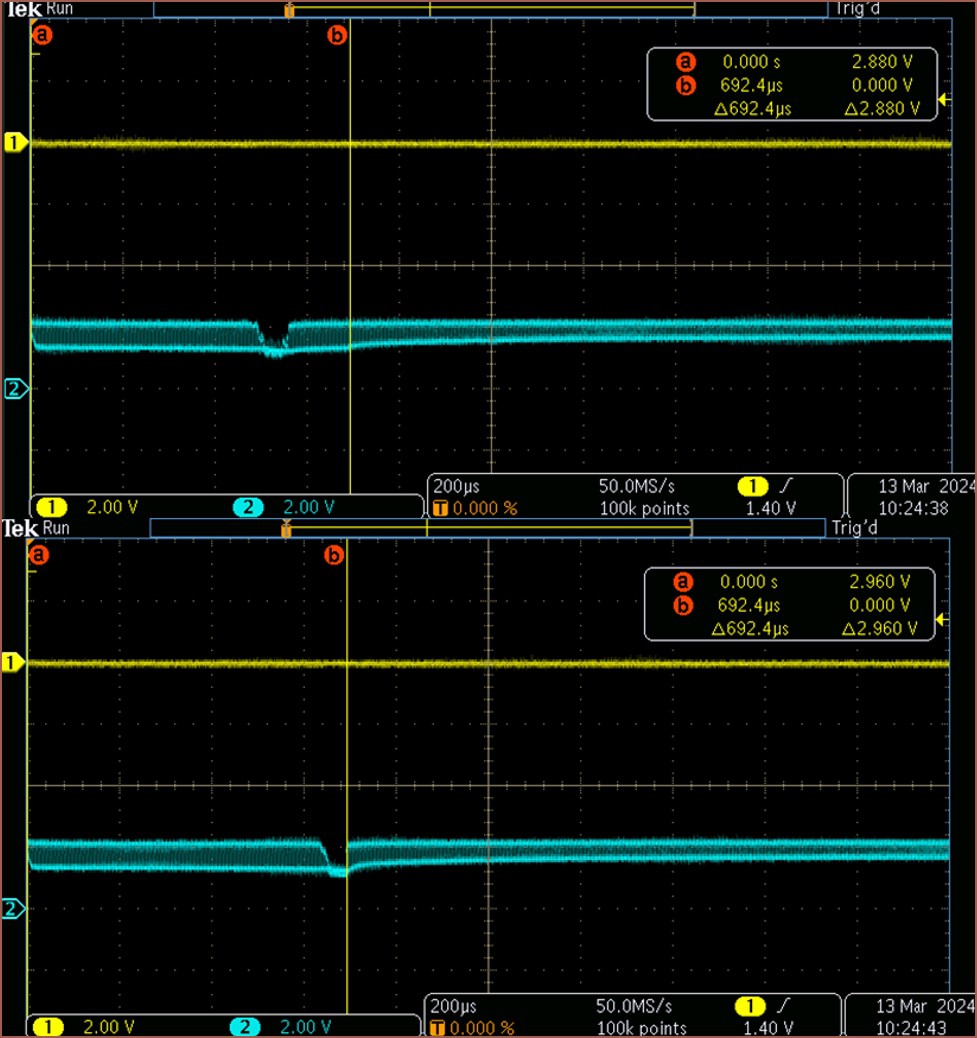
I actually found the exact point where the reading stops, as marked by the yellow "b" line:
Looking inside the sensor
While I was trying to reverse-engineer, I had some peeks inside the sensor itself:
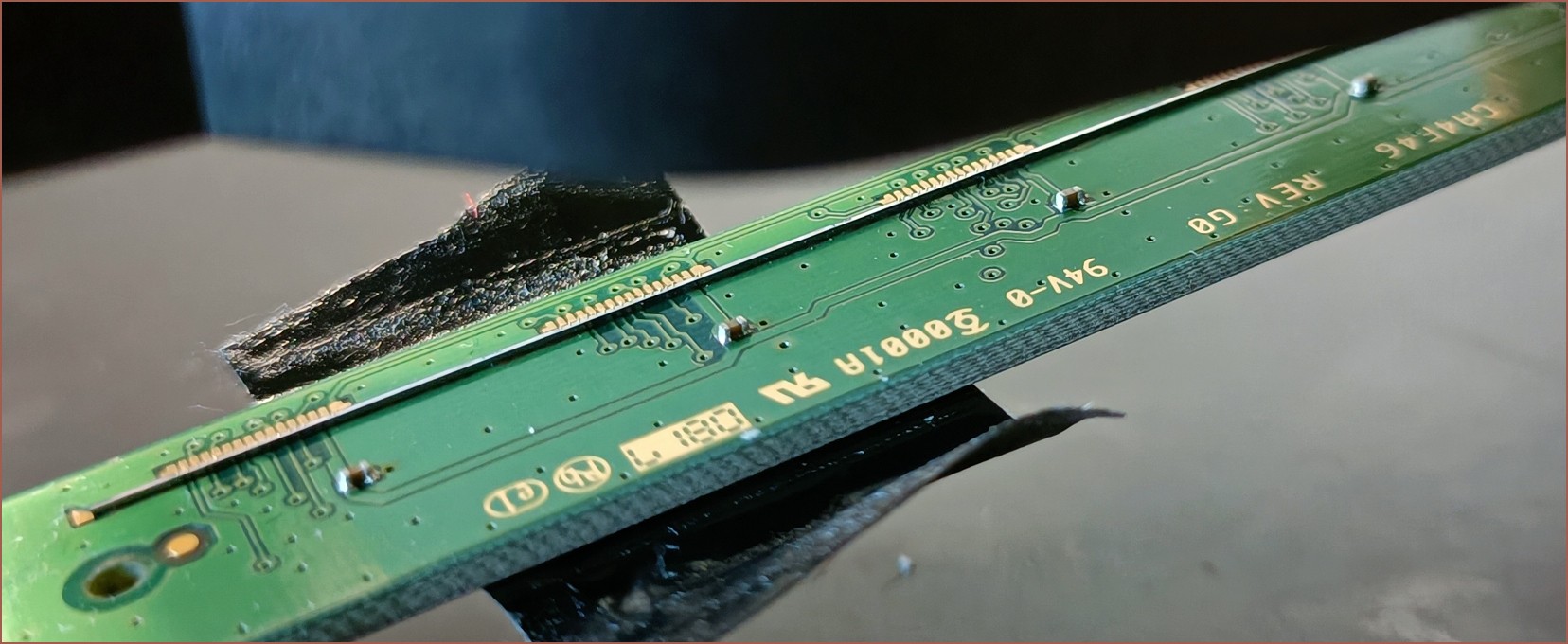
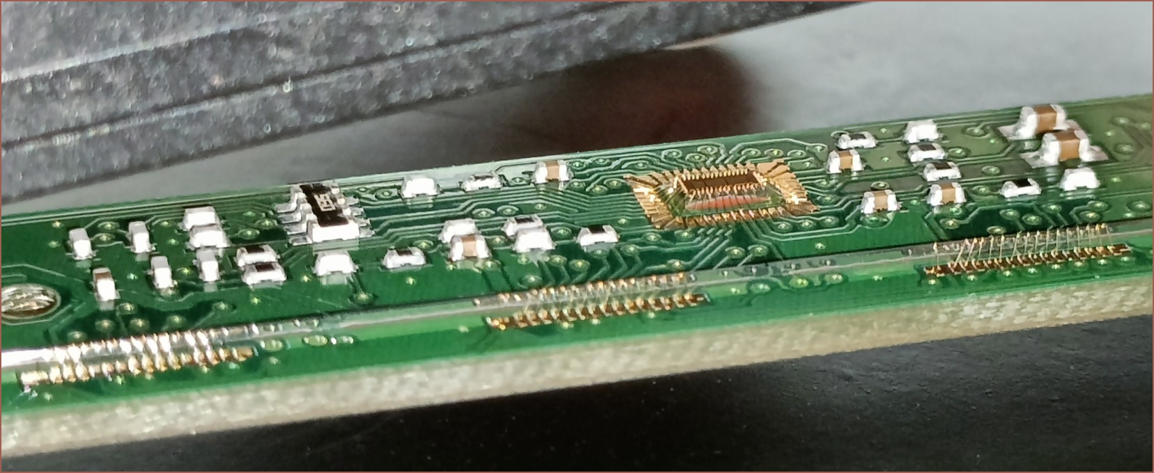
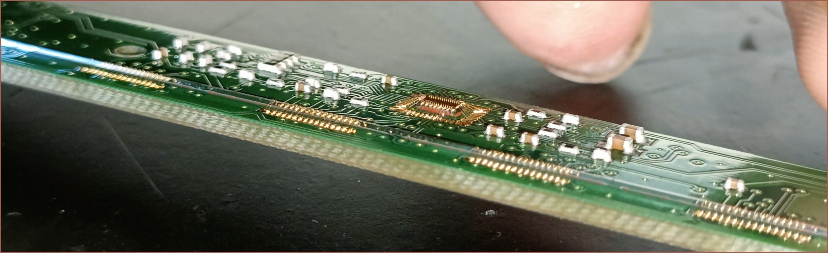
I don't think it helped in reverse engineering but it was nice to see all those thin gold wires. I noticed that there were 16 pads for these CIS but only 13 in the AMIS datasheet. I also think communications are going through that chip in the centre instead of being daisy-chained through each CIS. I get the impression from the readout that I'm stuck reading CIS_0 or something.
Discussions
Become a Hackaday.io Member
Create an account to leave a comment. Already have an account? Log In.