My processor needs the ability to compare 2 x 32bit values and output a simple true or false. In addition to the values it has a few control lines that indicate the operation (=, <, >=), if the comparison should be inverted and if the comparison is between signed or unsigned values.
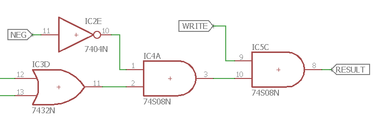
The design is split between a top board that does the basic comparison assuming the values are unsigned. Then the bottom boards take into account the negation and unsigned requirements. Doing a test on this bottom board shows it giving incorrect outputs for when the negation is applied. So I check the circuit design so I could start debugging. Well it didn't take long to find the issue. Here is the last stage of the circuit where it takes negation into account...

Well that is garbage. Instead of negating the output if the NEG input is true, it simply always outputs zero. So a quick fix solves the problem thus...

 Phil Wright
Discussions
Become a Hackaday.io Member
Create an account to leave a comment. Already have an account? Log In.