Maximiliano Palay
-
Updates
05/09/2023 at 01:15 • 0 commentsThis project has received two awards since its presentation,
- Best Engineering Capstone Project 2022, awarded by National Academy of Engineering of Uruguay.
- Best Engineering Capstone Project 2023, awarded by National Engineers Association.
As I have recently seen there is a category for assistive tech on the 2023 Hackaday Prize, I'll be adding a bit more info and submit this project to the corresponding challenge.
Hope this can bring a bit more visibility to the project and inspire others to create.
Wish me luck!
-
User tests!
06/27/2022 at 16:45 • 0 commentsTo avoid compromising the safety of anyone external to the project, I performed the tests myself using a splint. The splint was made out of aluminum extrusion and 3D printed PLA+, using the same nylon stars as the data capturing device. This enabled rapid testing and iterations over the control mechanism, which was -at first- useless. On paper and on the bench tests, the control scheme worked quite nicely. When the prosthesis was loaded with weight, it didn't work, basically.
Let me share a few thoughts that appeared with the tests:
- You have to trust the device. Putting all your weight and producing a full step seems easy, but it's not. It's quite difficult to trust the device and be sure it will perform as expected.
- The splint provides a limited degree of resemblance, although I think it's enough to test general functioning of the device.
- The user has to know the little quirks and movements that make the prosthesis work. Understanding its behavior and its causes seems to be fundamental in the process of learning how to use it.
- Using a prosthesis is tiring! After a few steps, I was already sweating - a lot.
This might seem trivial to some. But experiencing these things made me realize actually how hard it is to use a prosthesis.
After several tests and trips, I observed that when I stepped over the prosthesis, the thing gave in too much. It flexed the knee, producing a sensation of instability. But the neural network was performing ok, it's just that the training data shows that -presumably- at impact, the knee flexes quite a bit. Probably to dampen the strike on the ground. The data was then filtered to remove high frequency components, these "impact flexes", and the model was retrained. This helped very much with the problem.
Although the first tests looked quite terrible, they evolved into something much smoother. I had to learn to trust the device and produce full steps. The final tests are shown in the following video.
On this video, some gait deformations can be seen as a result of the prosthesis being too tall for myself. The prosthesis size can't be shortened on the current design. The prosthesis behaves correctly in swing and stance phases, extending and retracting as needed, resembling a biological limb.
-
Control scheme
06/20/2022 at 14:20 • 0 commentsA central part of this project. How is the prosthesis controlled? How does the user have to interact with it?
Typical control systems
Typically, intelligent prostheses use a range of sensors including IMUs, load cells and sEMG. The cheapest of these are the IMUs and thus the ones being used. A load cell could have been incorporated, and is useful to determine different events and gait phases. I couldn't find one with the necessary specs and cheap enough to include it in the budget.
These systems usually have a 3-level control scheme, with a top level which recognizes the user intention, a mid controller which is activated by the higher level controller, which determines the behavior of the prosthesis. And the lower level comprehends the controllers and actuation systems to make things happen.
This project's control, neural networks
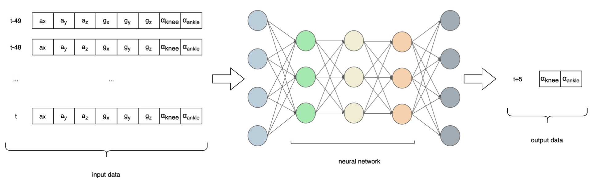
To break down such an immense problem, this project implements a two level control scheme, eliminating the highest level. That being said, the prosthesis always "thinks" the user's intention is to walk. The mid level controller is implemented using a neural network, which takes IMU data and joint angles for the 50 previous time steps and predicts the joint angles 5 time steps into the future.
Why a neural network? The answer results from a previous question, how do able-bodied people walk? The answer is quite difficult, honestly. It is a mostly automated process, we don't put a lot of effort into thinking what we have to do in order to walk. Directly interpreting data from an IMU to detect gait phases would be a hard task to say the least. This is where Machine Learning (ML) comes into play. If the IMU data has a correlation with the joint angles, a model can "learn" the relationship and it can then be used to make predictions.
Mid-level control scheme. The neural network takes a total of 400 numbers to predict both joint angles. Several neural network architectures were tested, including RNNs, LSTMs, and CNNs. As the control algorithms run onboard of the prosthesis, memory and runtime restrictions means the model cannot be too big or computationally expensive. This was implemented in Tensorflow, and optimized to run on a microcontroller using TFLM (Tensorflow Lite for Microcontrollers). At the time this was done, LSTM and RNN kernels were partially ported to TFLM, so the final NN had a few convolutional layers and a trailing fully connected network.
Data capturing
To train a neural network, there is a need to have data, lots of it. Typically, motion capture systems (MCS) enable the measurement of different stats that are useful to calculate the joint angles. Ideally, I would have used a motion capture system in combination with an IMU, and recorded data of several subjects walking to train the neural network. I couldn't find any dataset with these characteristics and the amount of data necessary for this application on the internet. Without access to a motion capture system, I decided to build my own. Nothing remotely close to an optical MCS, but at least I can grab data whenever I want to.
So I made this device that attaches to my right leg, with the use of straps and fixed footwear. It was built using 3D printed parts and aluminum extrusions. Two AS5600 magnetic encoders measure the joint angles, and an IMU attached to the front part of the leg, above the knee, measures 6DOF data. These three sensors are connected to an Arduino Nano using an i2c multiplexer (the encoders have hardcoded addresses). The Arduino measures raw data from the sensors, creates a string with all the data in a CSV manner, and sends it through the serial port to a host computer, which registers the data. This happens at 50Hz.
Thanks to my uncle for lending me his treadmill!
Inverse & forward kinematics
The prosthesis does not use encoders at the joint origins. It is necessary to know the joint angles using the motor encoders. This requires a forward kinematics models that, knowing the motor position, enables the calculation of joint angles. This is possible as there are no elastic elements in the actuation system. If elastic elements were present, encoders at the joint axes would probably be necessary.
Knowing the target joint position, we have to know what position the motor should be in to accomplish the target. This uses an inverse kinematics model.
Both problems were solved geometrically, although using different techniques.
Control loop
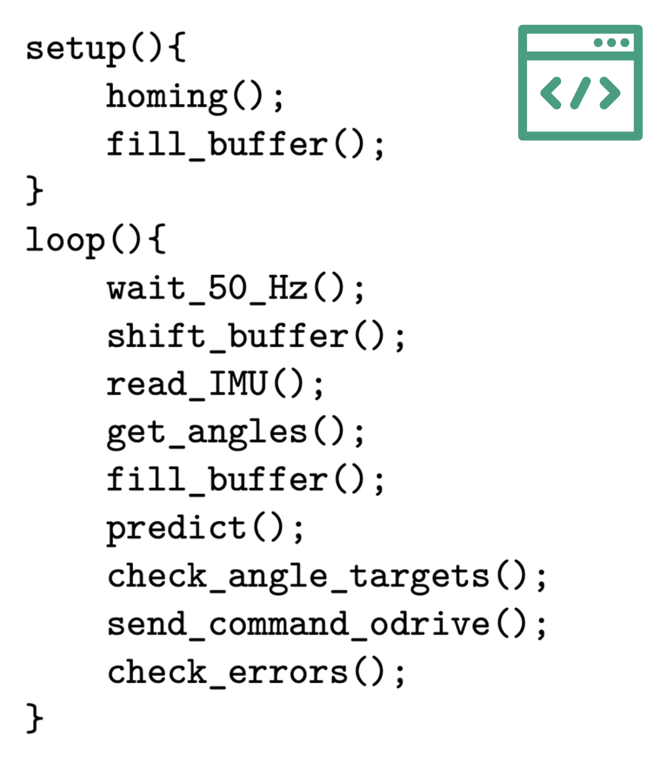
The control loop was implemented in Teensyduino, and runs at a frequency of 50Hz. A Pseudocode image is attached. Basically, the program reads the sensors, shapes the data to deliver it to the neural network, asks for a prediction, it checks that the prediction is in the range of software limits and sends the target position to the Odrive through UART.
Pseudocode of the implemented control loop on Teensyduino. As the used encoders are relative, a homing procedure is performed on boot up. The procedure puts the Odrive on torque control mode and drives the joints toward physical end stops, when the system detects the joints aren't moving any more, it assumes the joints are at their hard limits, and therefore knows the position because it is defined by design. You'll find a hyper lapse of this procedure.
A buffer with 400 positions is filled for the first time, using real IMU data and joint positions. The wait_50_hz() function halts the loop if necessary to respect the 50Hz running frequency. Shift_buffer() shifts the 400-value buffer 8 positions to the left, discarding the oldest data and making way for the most recent values, it is a FIFO buffer. Read_IMU() is pretty self explanatory. Get_angles() uses the motor position and a forward kinematics model to estimate the current joint positions. The fill_buffer() adds the latest data to the buffer (six values from IMU and two from joint angles). Predict() requests a prediction from the neural network. Check_angle_targets() checks that the neural network predictions are within software defined limits. Send_command_odrive() sends the desired target position of each joint to the Odrive using the ASCII protocol. Check_errors() checks communication with the Odrive is active.
Static tests
With a ready to use prosthesis and some preliminary control algorithms, it is time to test the behavior. A few static tests enabled review of the behavior before proceeding to a much riskier user trial.
This is just a video of me moving the IMU and observing the prosthesis response.
-
Mechanics first tests!
06/11/2022 at 22:17 • 0 commentsIt's time to test the actuators in place! Although the movement was simulated in Fusion360, there's nothing like seeing the real deal. Any problems with design or manufacturing could have affected the physical model. Some hand-powered movement tests were already performed to ensure the mechanism behaves properly. Now, let the motors power the mechanism.
This was performed using a python script and odrivetool, with a couple of set points that move the joints back and forth. You get some slow-mo as well!
It's evident on the higher speed tests that the noise level is quite high. Probably, this is due to the plastic structure resonating and actually amplifying the noise.
Some wiggle is noticeable on the slow-mo footage. This was improved with torquing the ball nut to the rotor assembly, so it had the same torque on all four attaching screws.
On to the proper control systems!
-
Assembly
06/05/2022 at 23:12 • 0 commentsAssembling the prototype was the last step to transition into the control side of things. Although I have been designing the control scheme since the beginning, the real tests are about to come. More on this on a future log.
The assembly consisted of two main stages, mounting the actuation system first (joints blocks and actuators), and then mounting the electronics and making the necessary connections. The following time-lapse briefly shows most of this process.
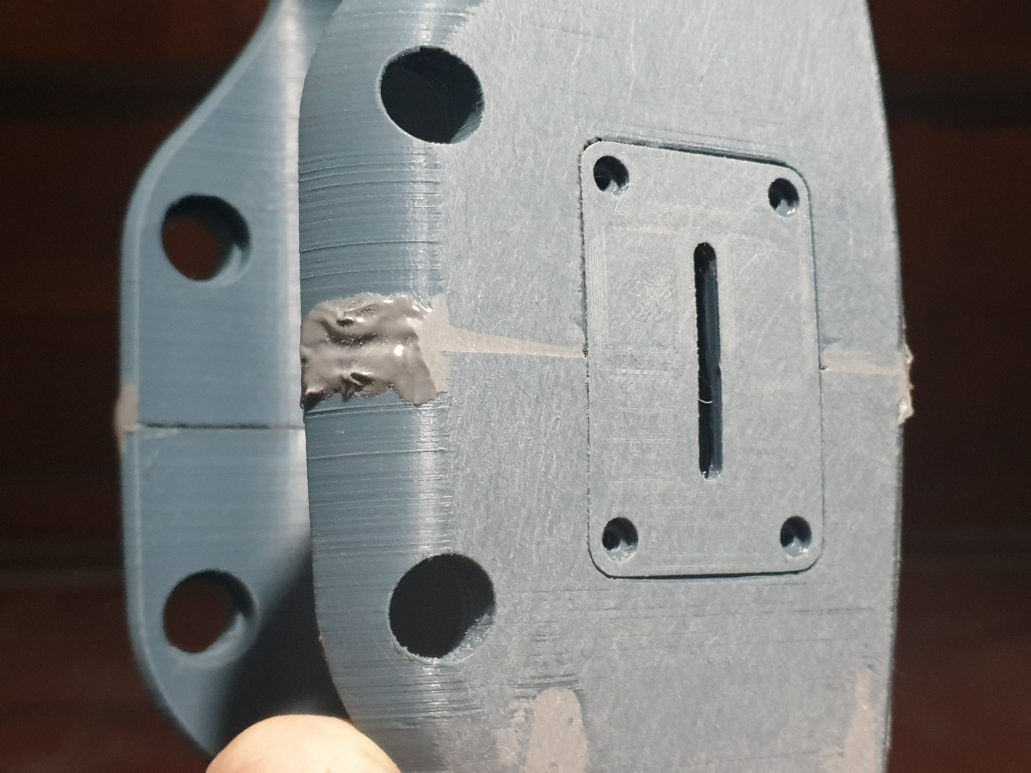
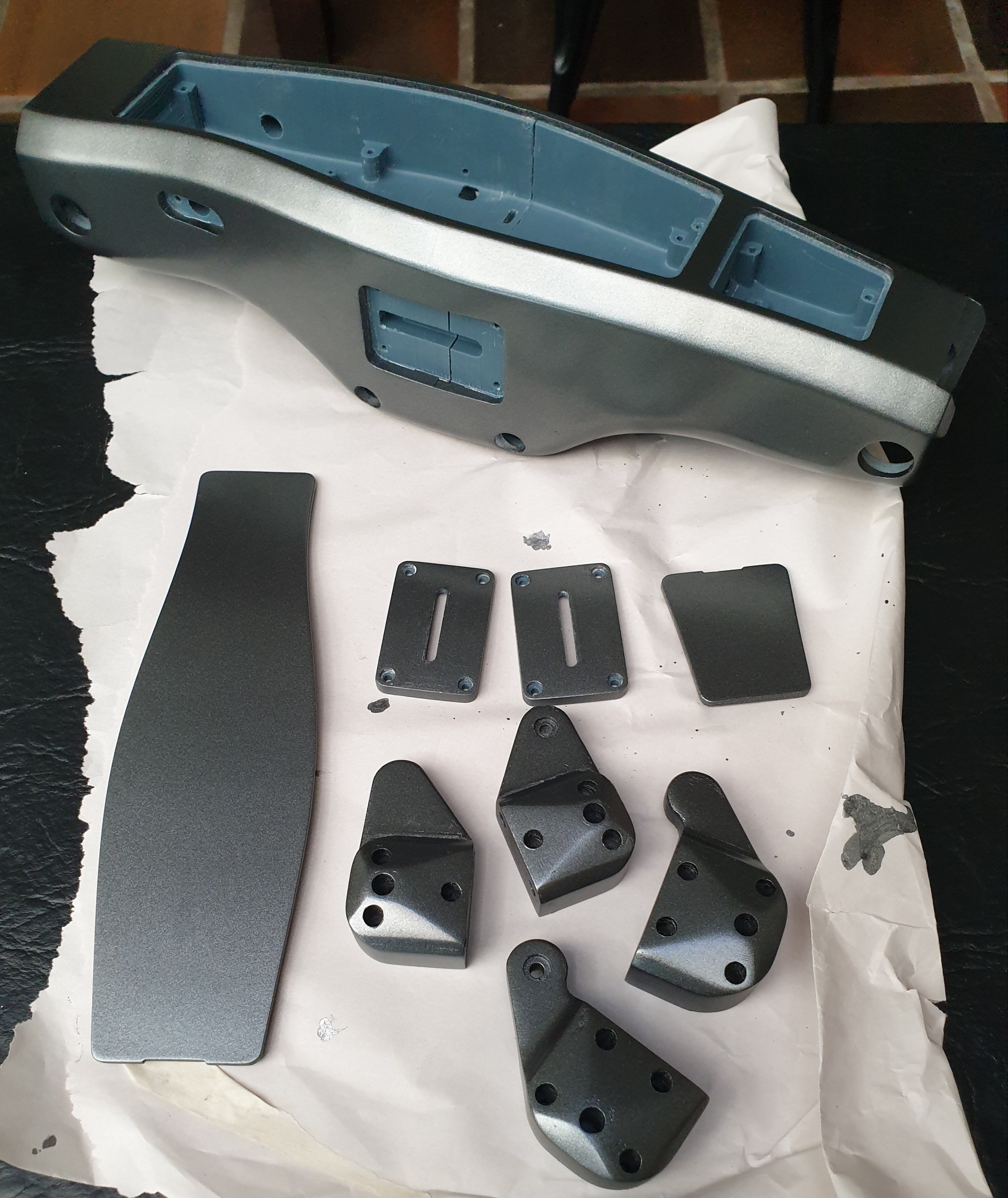
A few snapshots. You might see knee and ankle blocks with metallic paint and raw black. This was because these required a few modifications. The final ones are black.
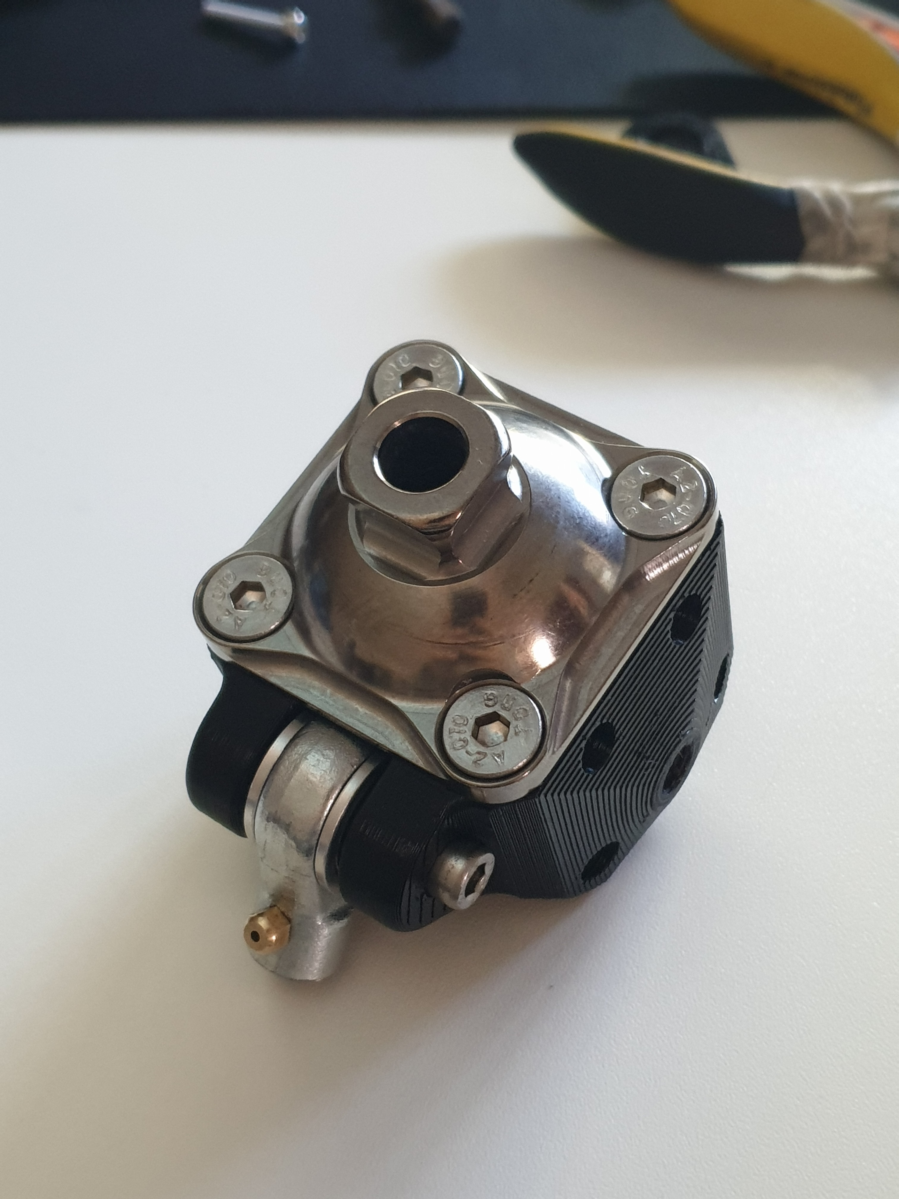
![]()
Final knee block with rod end and pyramid adapter in place. ![]()
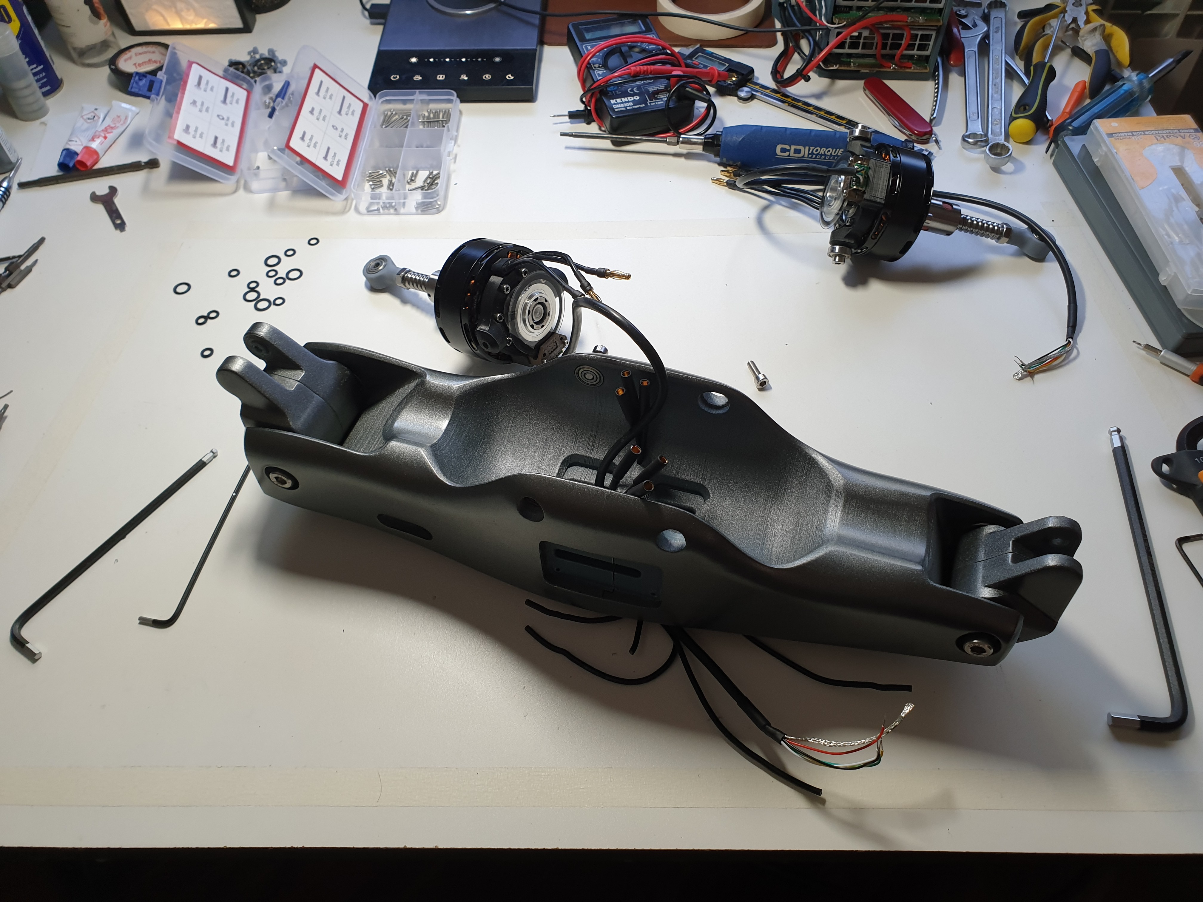
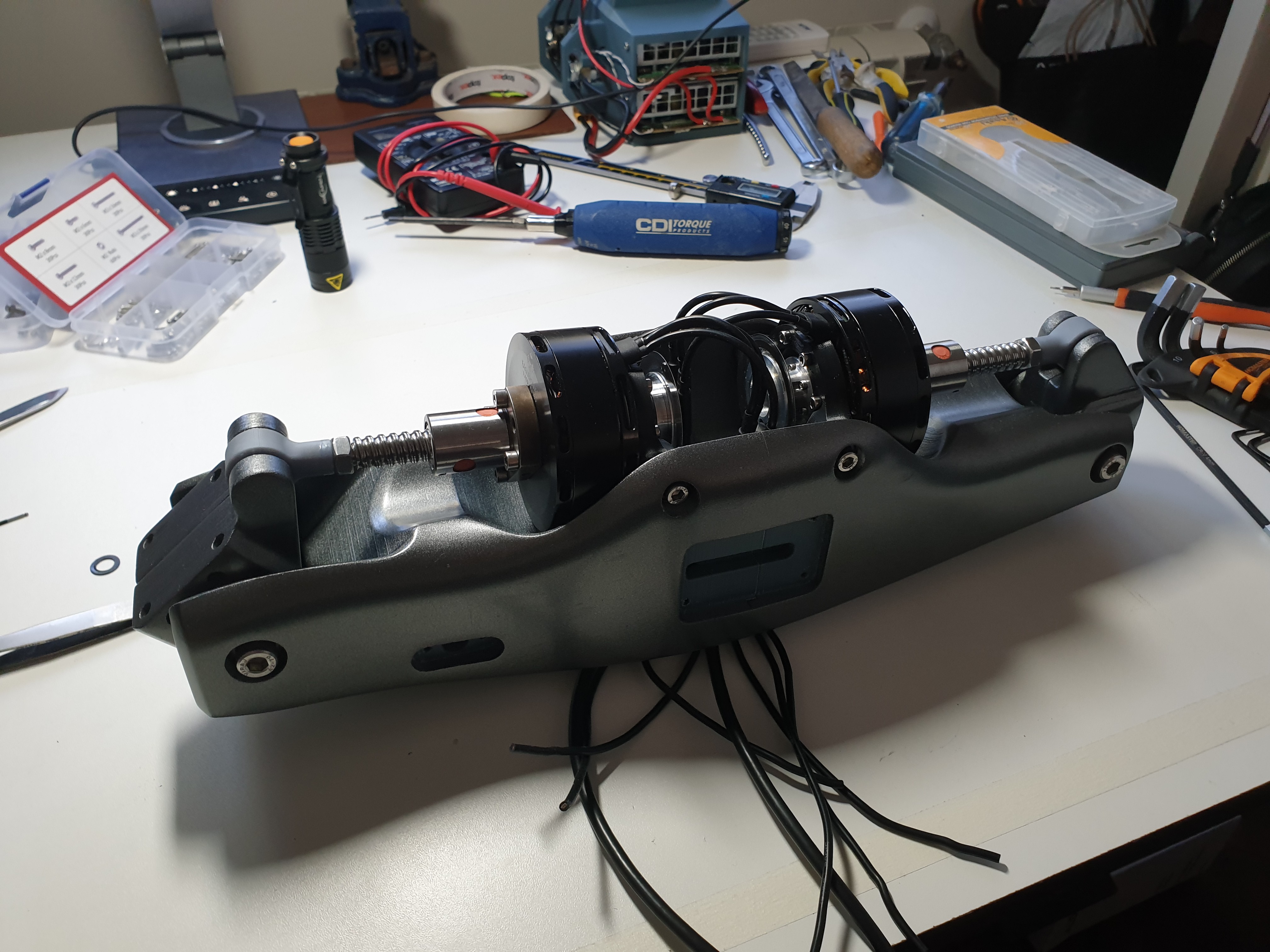
Rear view of the prosthesis and unmounted motors with the 3-phase motor cables already passed through channels that communicate the electronics cavity with the back. Both joint blocks are already mounted. ![]()
Actuation system mounted. Wires are routed and coming out the front cavity. ![]()
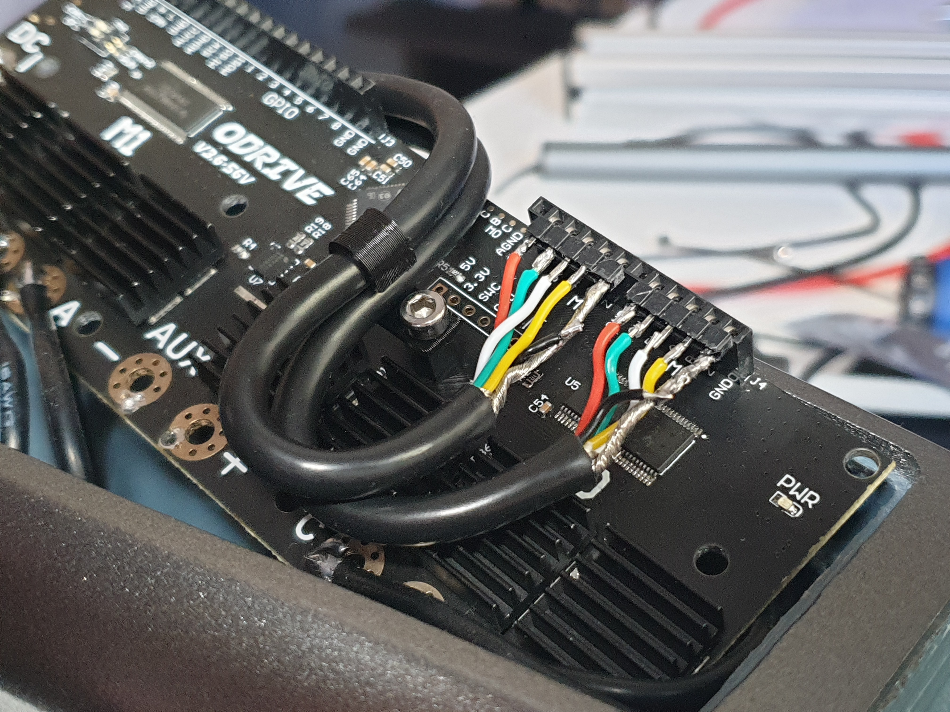
Odrive about to be secured in the front cavity. A 3D printed clip keeps the encoder cables neatly routed. ![]()
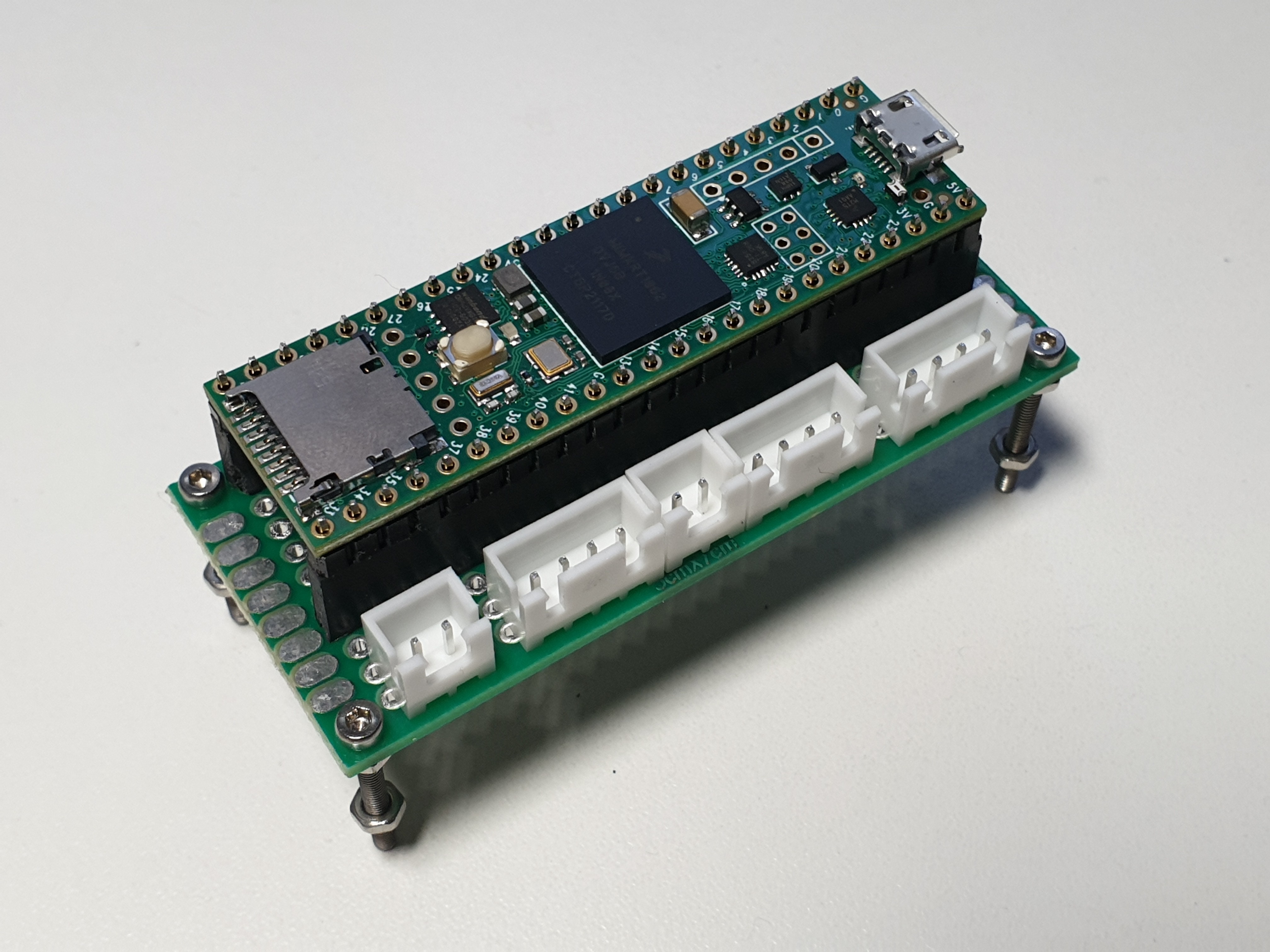
A self built breakout for the Teensy 4.1 with JST connectors for ease of assembly/disassembly. Connectors for power, power and I2C for the IMU, both RGB LEDs and UART for the Odrive. ![]()
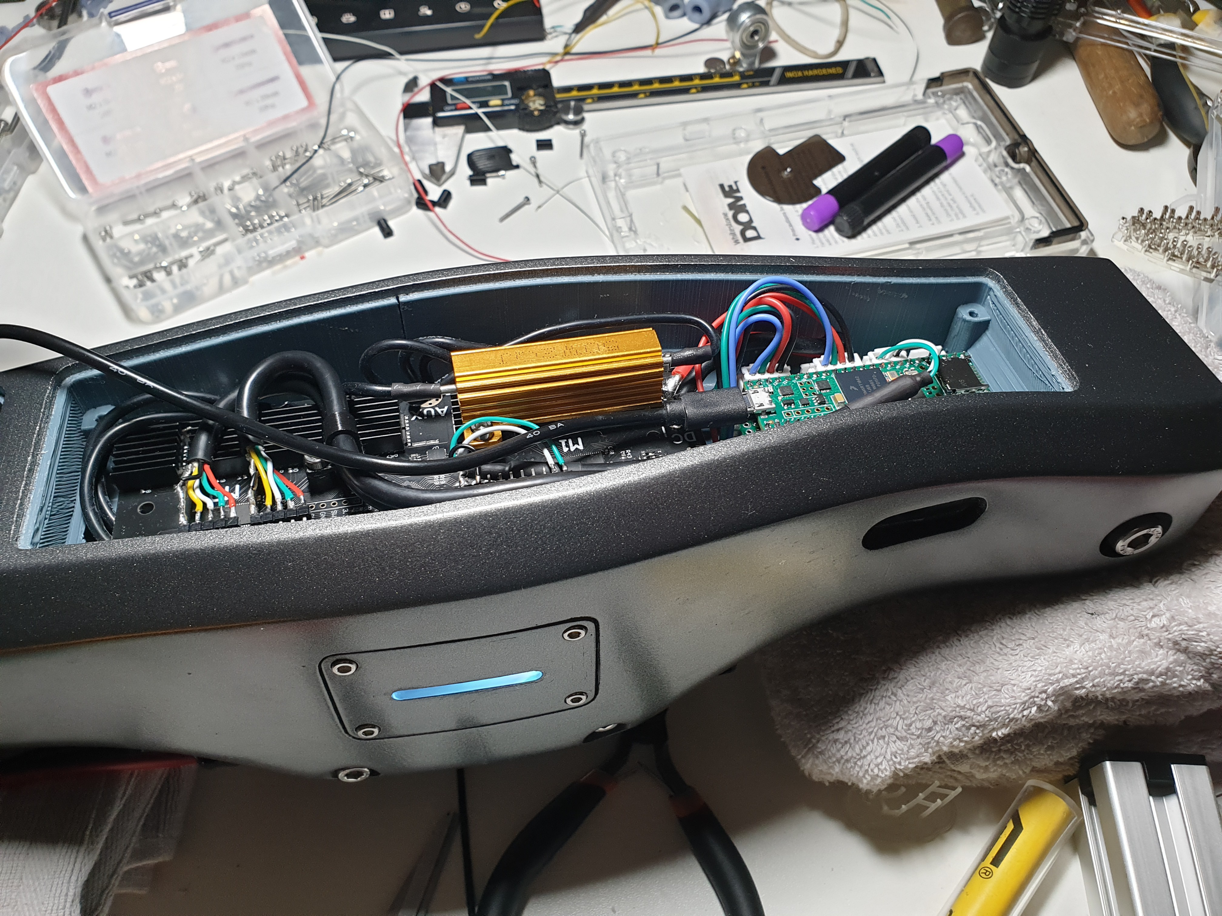
3/4 view of the prosthesis with electronics in place and LEDs on. -
Structure post processing
05/27/2022 at 15:52 • 0 commentsAfter finishing the 3D printing process, the next step was gluing the two body halves together. The design incorporates four channels to place four threaded rods at the joint to strengthen the structure.
Had to remove A LOT of support structures.
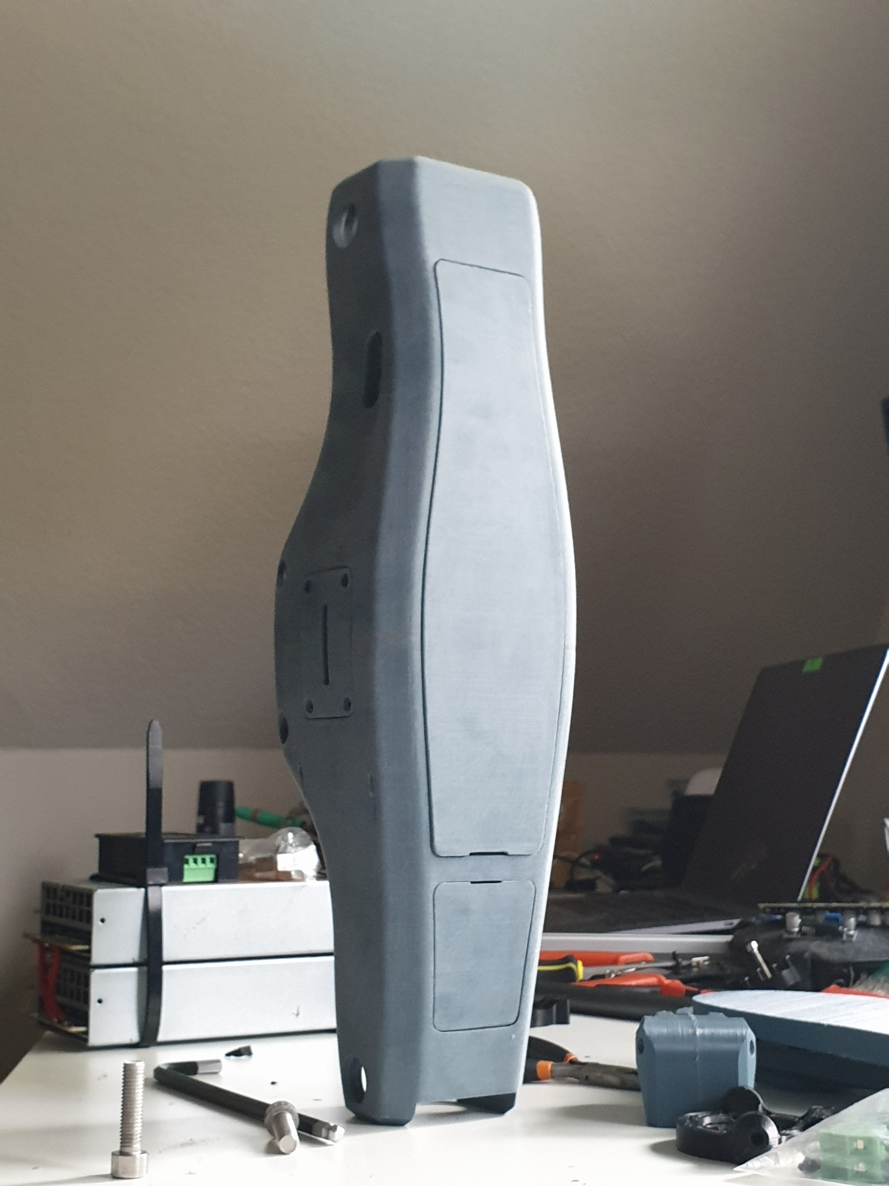
After joining the two halves together with the help of epoxy and the M3 threaded rods, the time came to make this look good. The quality out of the printer isn't as good as an injection molded part. Of course not. But I wanted a look that resembles a commercial product. It could be metallic or plastic, but smooth surfaces.
Using a pneumatic sander, the surface was smoothed down to 360 grit.
![]()
Sanding down the unified structure. Although this was at an early stage, the contrast between sanded and unsanded is clearly seen. ![]()
Sanded down structure. The real aesthetic magic was done with the paint job. It provided a metallic look. This was carried out by an auto body shop, which painted it with regular automotive grade paint and applied a clear coat on top.
![]()
-
3D Printing
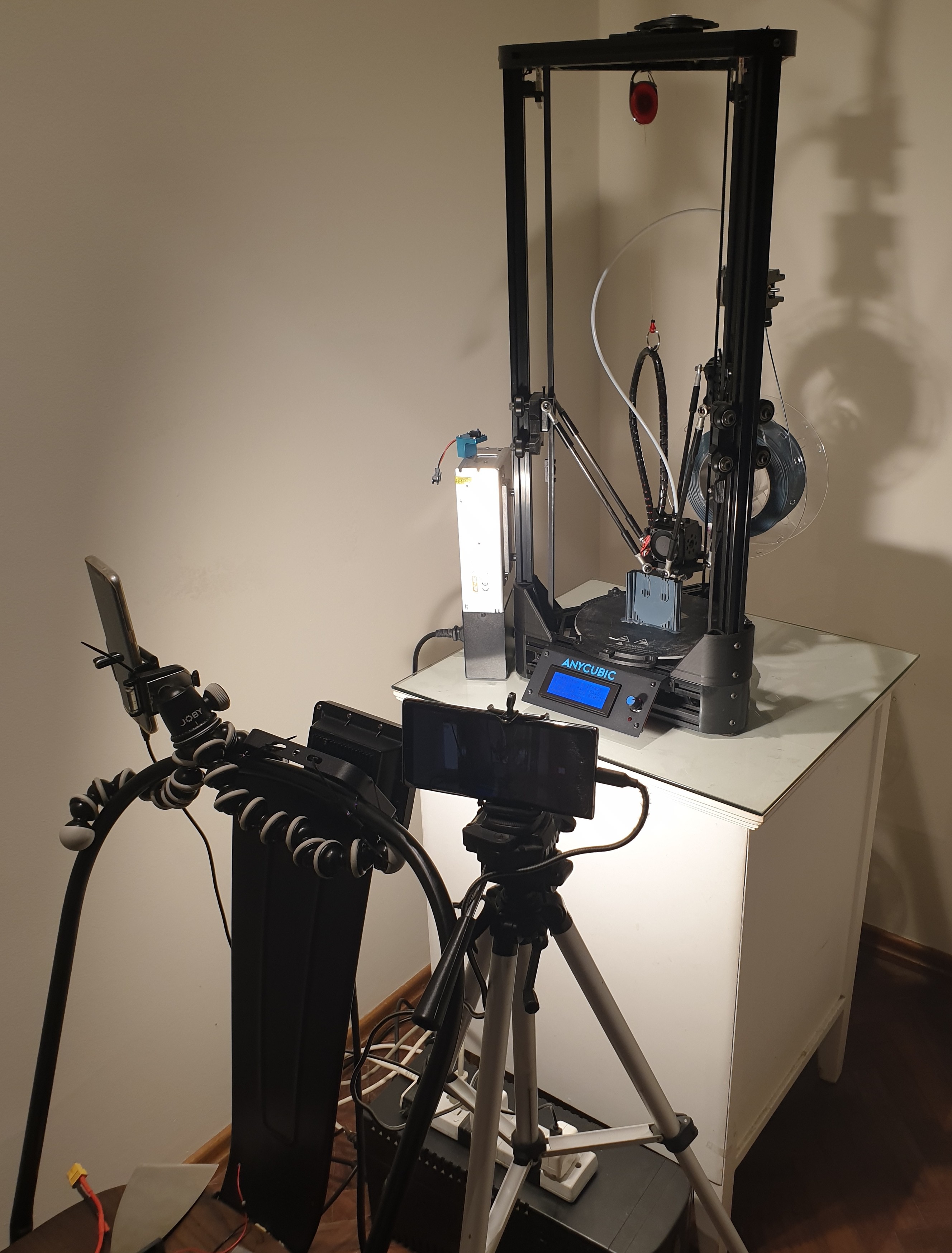
05/25/2022 at 15:02 • 0 commentsWith over 20 3D printed parts, this was a long process. The printer used is an Anycubic Kossel Delta. 0.15 mm layer height. Just regular PLA+. Different infill and parameter configurations for different pieces.Overall printing time was about a week. Made a small setup to capture some timelapses. Had to be on the safe side with a UPS, and as some prints were multiple days nonstop, the room temperature was "controlled" with an AC.
![]()
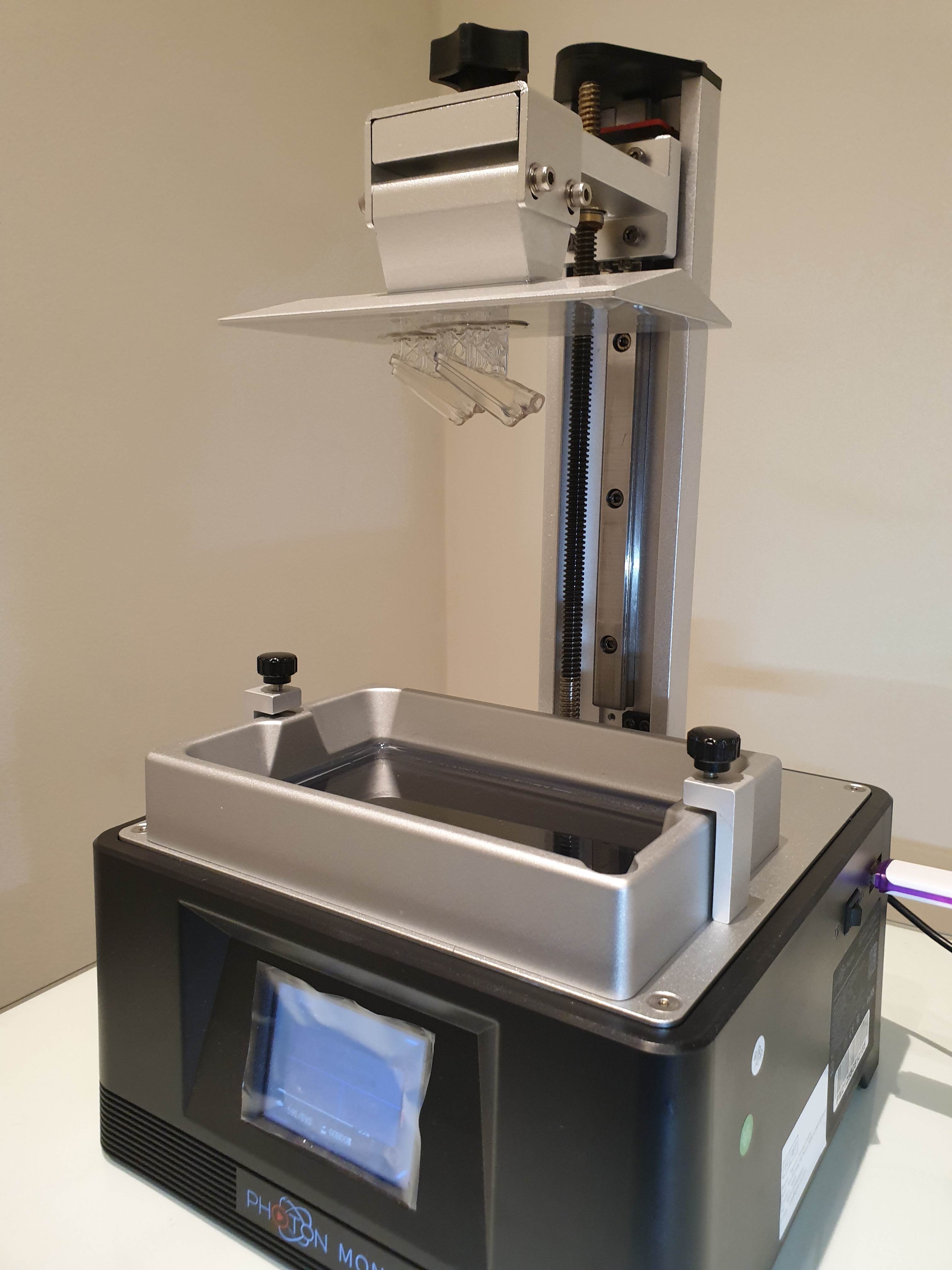
3D printing setup. Anycubic Kossel, UPS, a very [un]professional lighting setup, and smartphones setup to capture time lapses. The LED diffusers were printed with clear resin on the Anycubic Photon Mono.
![]()
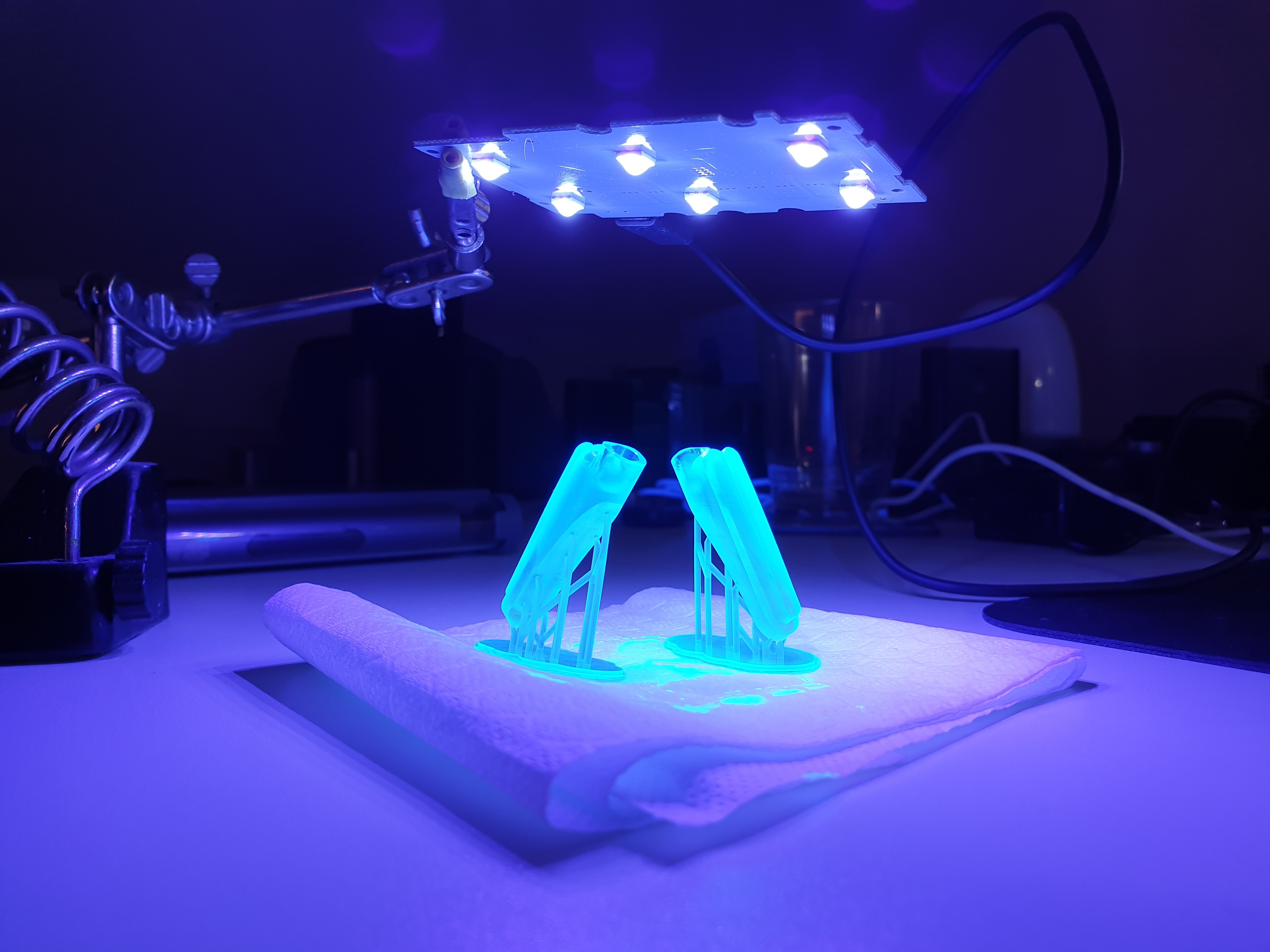
LED diffusers coming out of the Anycubic Photon Mono. ![]()
LED diffusers being cured with UV light. -
Actuators - Assembly
05/18/2022 at 22:38 • 0 commentsA video of the assembly does a better job than I can at explaining the procedure. It is rather simple once all the components are ready. The hardest part is probably mounting the encoder disc on the rotor and securing the encoder sensor on the motor mount. Temporary 3D printed rod ends are shown in this process.
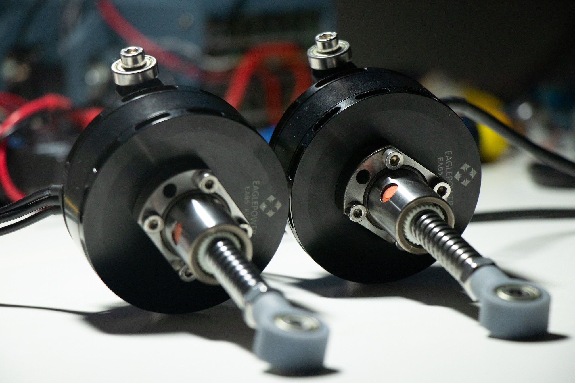
I'll leave a couple of snaps of the finished products as well.![]()
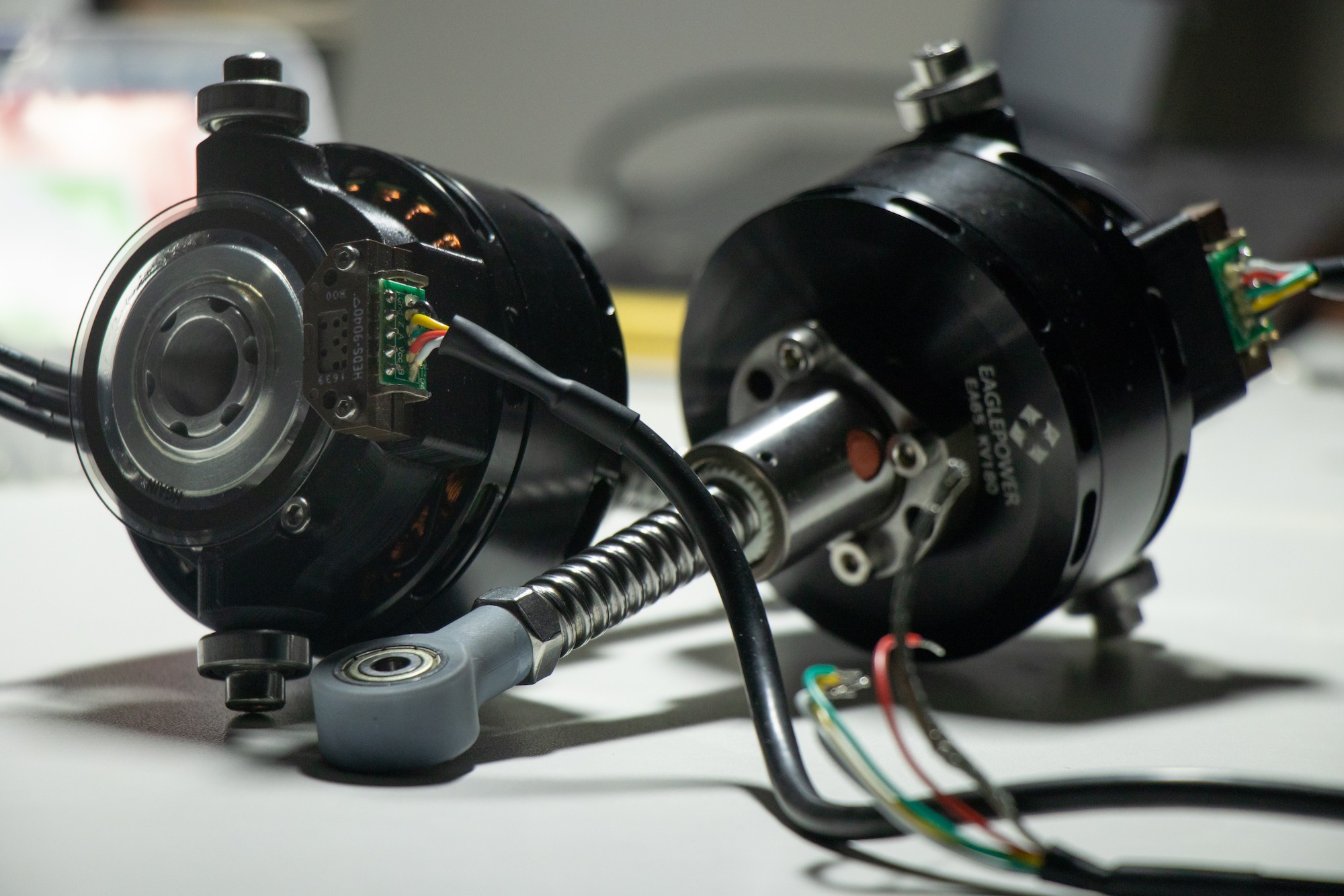
The finished actuators side to side. On this image, temporary 3D printed rod ends are shown. ![]()
The finished actuators facing each other, front and rear views. On this image, temporary 3D printed rod ends are shown. -
Actuators - Fabrication updates
05/17/2022 at 19:11 • 0 commentsI'm dropping a few pictures from visits to the machinist.
The design required the stock 1204 ball screws to be cut down to proper length, and an M8 thread was machined on one end of each. Furthermore, rod ends were adapted to restrict the ball joint to a uniaxial rotating joint with bearings. Originally, newly fabricated rod ends were on the plans. But the machinist offered to modify existing ones which would simplify the fabrication and reduce overall costs.

First visit to the machinist. The original rotors are covered in tape to protect them from scratches. These already have the center bore and the four holes for mounting the ball nut. At the top of the image, the ball screws are shown already cut to length and threaded. Parts of the 3D printed prototype can be seen with a navy-grey color. Some aluminum parts with progress pending can be seen as well. 
The modified rotor with the new axis press fitted can be seen at the left of the image. The angular contact ball bearings are over the rotor. At the top right, the modified stator with the original bearing seats removed, and the new aluminum piece fitted inside. This piece was glued with anaerobic cement. At the bottom right, the crown. 
One of the modified rod ends, without bearings. The original ball joint was removed and two bearing seats were machined from aluminum and press fitted into the original rod end casing. -
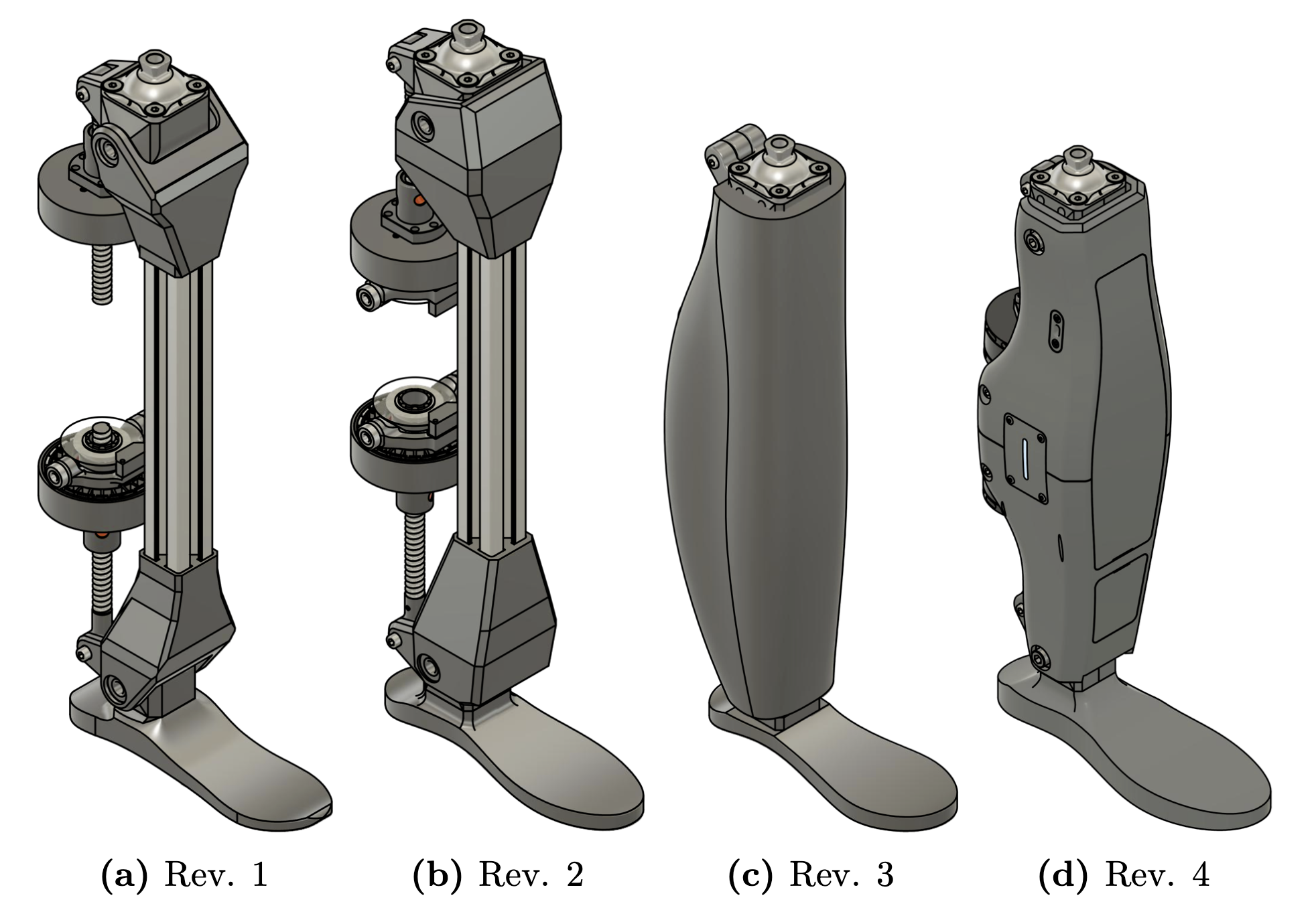
Body Design
05/15/2022 at 13:47 • 0 commentsAs shown in the concept image, the prosthesis was to be manufactured using a 30x30 mm aluminum extrusion as the main structure, and 3D printed components around it to hold everything together. This had numerous advantages, such as ease of assembly and disassembly, a large amount of mounting points (or rails) over the four sides of the aluminum profile. These are key points for working on a prototype.
The main disadvantage of this concept is volume. The profile takes up space which could be more efficiently used, distributing the greater surface and not having it on a column shape would enable placing of electronics on the inside of the prosthesis, rather than mounting everything around the extrusion. The latter would result in a bulky prototype.
After a couple of revisions (Revs 1 and 2), this initial concept design was halted. It wasn't just about the volume, it would be very difficult to make it look good too. Revision 3 was all about "let's see what I can come up with in a few minutes, dreaming about fully printing it in 3D". This resulted in more of a leg shape right off the bat. Sketches of a design were then paper-drawn, and a more though out model was created. This generated the fourth and final revision.
There's a myriad of design aspects, issues and solutions to talk about. I'll highlight a few things. The prosthesis begins with a pyramid adapter at the top that enable it to interface with existing prosthetic sockets. The main body is split in half since the design phase, because the 3D printer to be used does not fit the whole body at once. The foot requires much more design to provide proper damping and suspension, in this case, the foot is just support. This project focuses on creating a functional prototype, and the foot is left for future improvement. The electronics are held inside the body inside two frontal cavities, which are enclosed by covers that are held in place using magnets. This allows for the covers to be easily removable without any tools. This is a plus for showing and explaining the project. The internal electronics cavities have several mounting holes to attach the components with screws.
The whole assembly is over 150 pieces.
The knee and ankle were designed in a "block" fashion. These are kind of like rotating blocks over an axle, hence their name. In the exploded view animation, both blocks are shown to be cut inn half. This is to enable a more symmetric fabrication and have the layers aligned with the direction of greater stress. Each block's halves are joined together by M3 screws and nuts.
Used bearings are 608 for the joints axes and 625 for the motor mounts. The axes are M8 and M5 screws respectively.
The model has two lateral panels with LEDs to communicate the prosthesis status to the user. And you can't deny these are aesthetic A*! The LEDs to be used are RGB, placed in combination with a diffuser that "shapes the light" to its slot form.
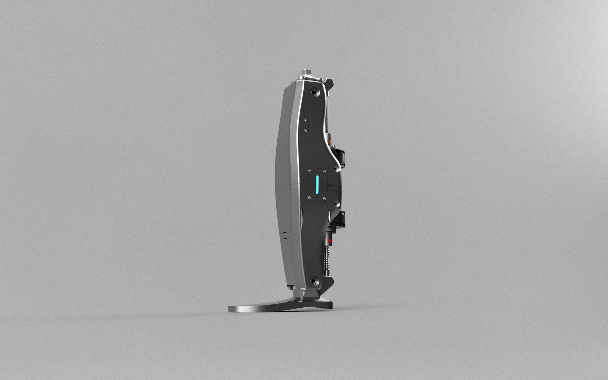
![]()
3/4 render of the prosthesis.
Affordable bionic prosthesis
This project aims to create an affordable lower limb prosthesis for above knee amputees using hobby grade components.