 Nick Sayer
-
1Installing the through-hole parts (LEDs)
When you get the board, all of the surface mount components will have been installed and programmed.
First, install the two .56" 7-segment LED modules for the seconds and tens-of-seconds digits and the two .56" 7-segment LED modules for the hours and tens-of-hours. Make sure the modules sit flat against the board. For each module, solder a single lead and double-check that the module is oriented correctly (decimal point on the bottom) and sits flat against the board. Solder the rest of the pins.
-
2Step 2
Install the small .3" 7-segment LED module in the tenth-of-a-second spot on the right side of the board. For best results, mount the module so that the top edge lines up with the top edge of the larger modules. The easiest way to do this is to insert the module into the holes and then lay the board face down so that both the .56" modules and the .3" module are resting flat on the surface. Done correctly the 10th-of-a-second digit will be up about 1/8" from the surface of the PCB. Solder just one pin on each corner and verify that the module is straight, oriented correctly (again, decimal point at the bottom), and the top lines up with the top of the second digit before soldering the rest of the pins.
-
3Step 3
Install two 3mm LEDs for the colon between the minutes and seconds. The short lead of each (the cathode) should be towards the top. Install the two LEDs so that they're about 1/8" up from the board - that is, so that their tops are at or just below the top face of the adjacent 7 segment display. To do this, you can use the same trick as for the 10th-of-a-second digit - insert the leads and flip the board over and allow the LEDs to rest against the work surface along with the 7 segment modules. Solder one lead of each and carefully verify that each LED is the same height up from the board and is plumb in both directions (from the top and side). Once both LEDs are positioned correctly, solder the remaining leads and trim the excess lead lengths.
-
4Step 4
Repeat step 3 to install the hour-minute colon, then step 1 to install the minutes digits.
-
5Step 5
Install the two 5mm LEDs for AM and PM. Look for a flat spot on the collar of the LED body and place that against the flat spot on the outline of the silkscreen on the board (for these LEDs, sometimes the anode is the long lead rather than the cathode, but the flat spot is always the cathode side). Make sure the LEDs sit flush against the board and bend the leads apart on the opposite side. Then solder the leads and clip off the excess lead length.
-
6Step 6
Plug in the power supply and GPS antenna to test the result. All of the LEDs (except FIX) and all segments of the LEDs should light up for a second and the display should change to show the GPS receiver firmware date, then "no GPS" with the FIX LED on solid. In a half a minute or so (presuming good reception), the FIX LED should start to blink and the display should switch to showing U.S. Pacific time. Remove the power and antenna connection for case assembly.
-
7Assembling the board in the laser-cut wood & acrylic case
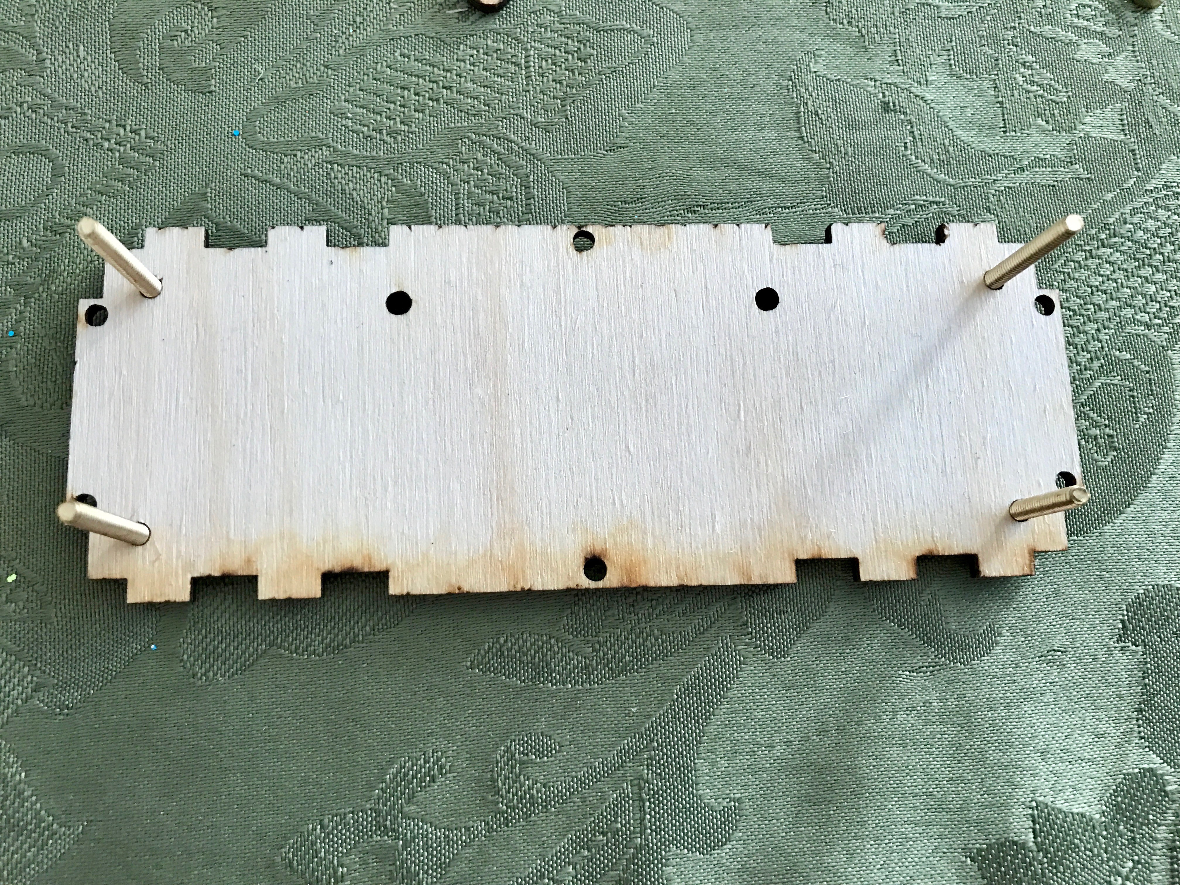
Place the case back face down on your work surface (writing down). Orient the board so the switch holes are at the top. Insert a 1" 4-40 machine screw through the back of each of the 4 PCB mounting holes.
![]()
-
8Step 8
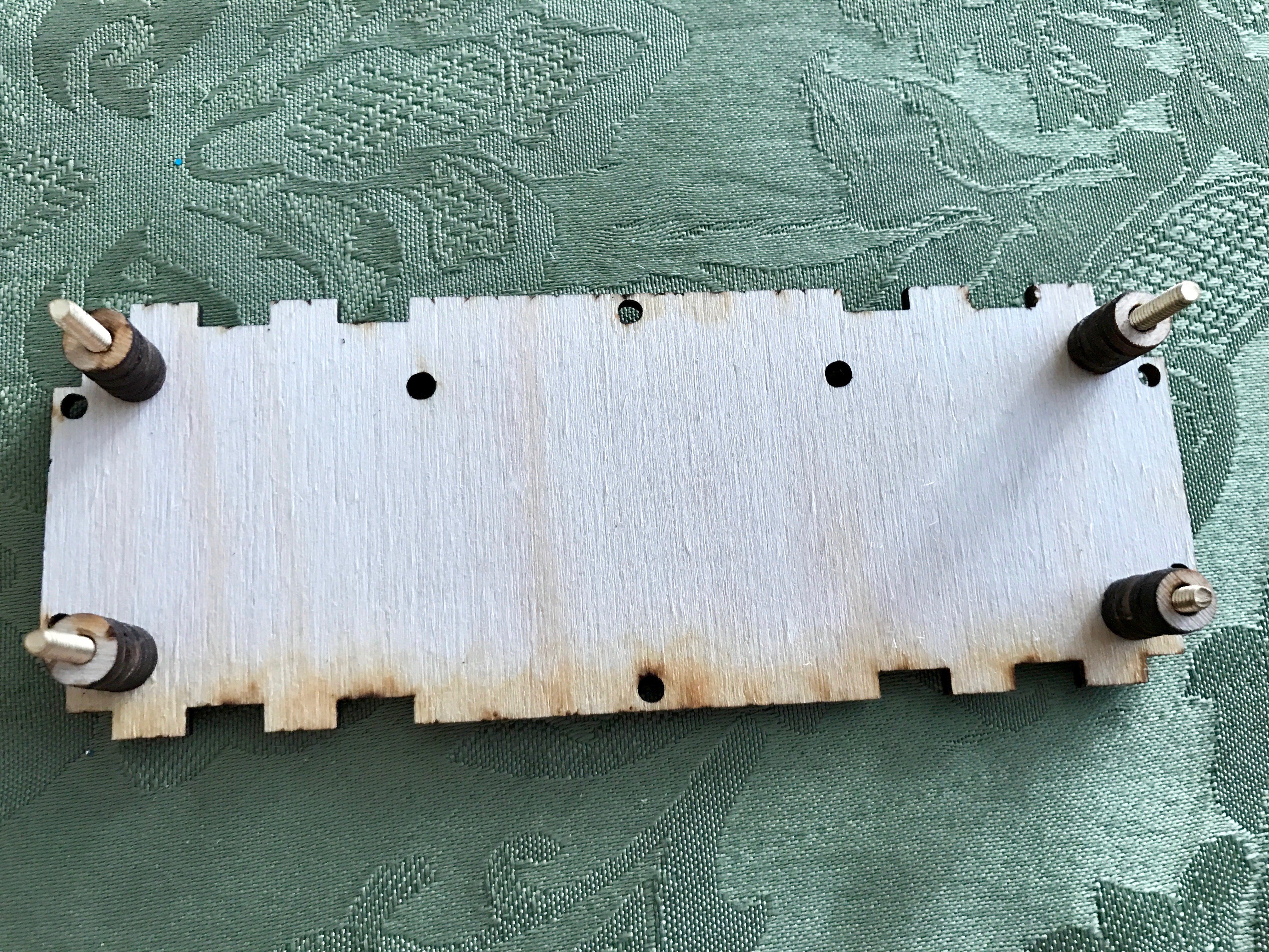
Add a spacer onto each screw (in some cases, you get 16 thin washers instead. Use 4 of them for each screw).
![]()
-
9Step 9
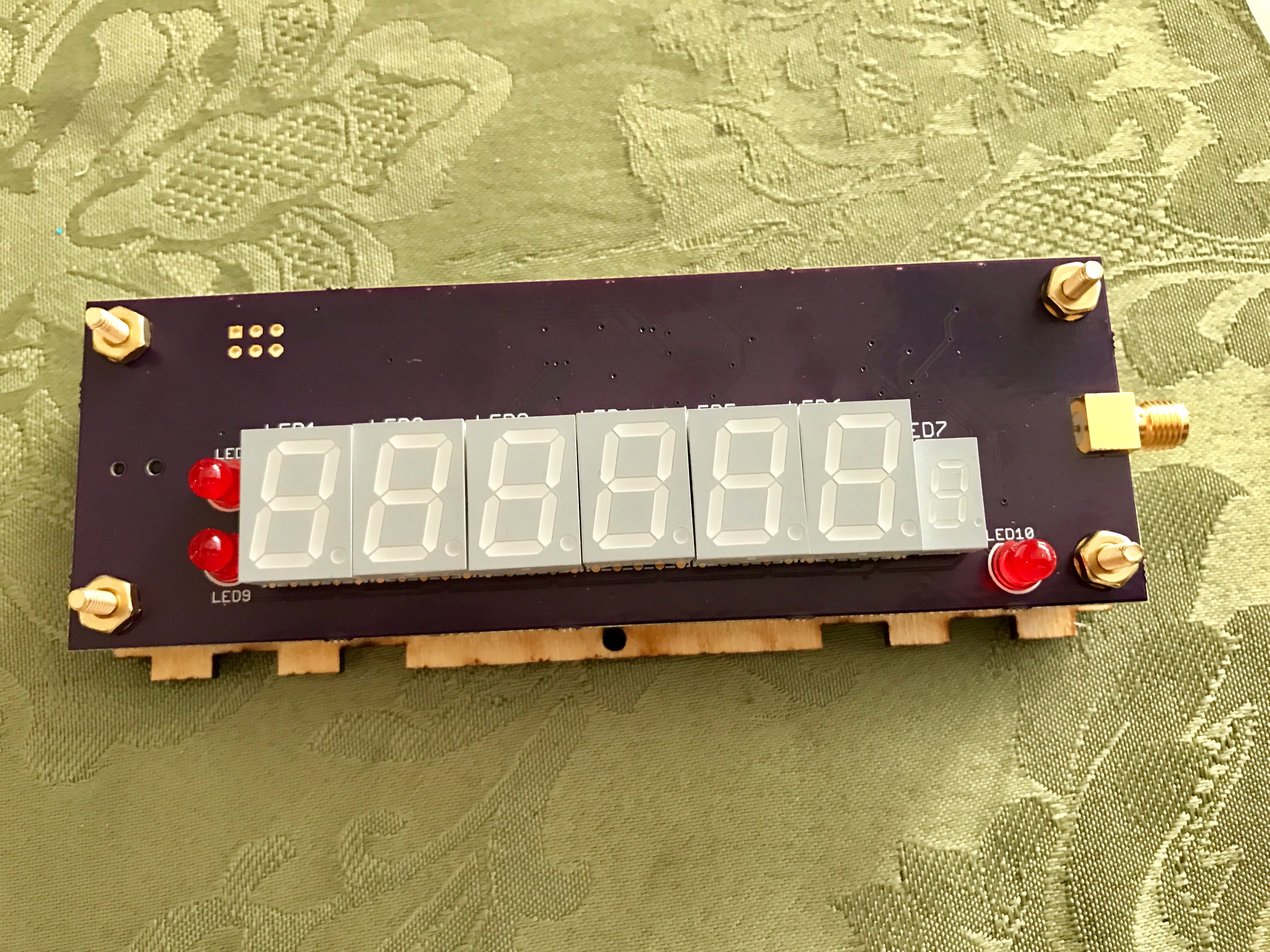
Place the board on the screws with the switches on the back sticking into the switch holes. Add a lock washer onto each bolt and then a nut. Before tightening each nut, double-check that the switch posts are correctly placed in the switch holes and not jammed against the back panel.
![]()
-
10Step 10
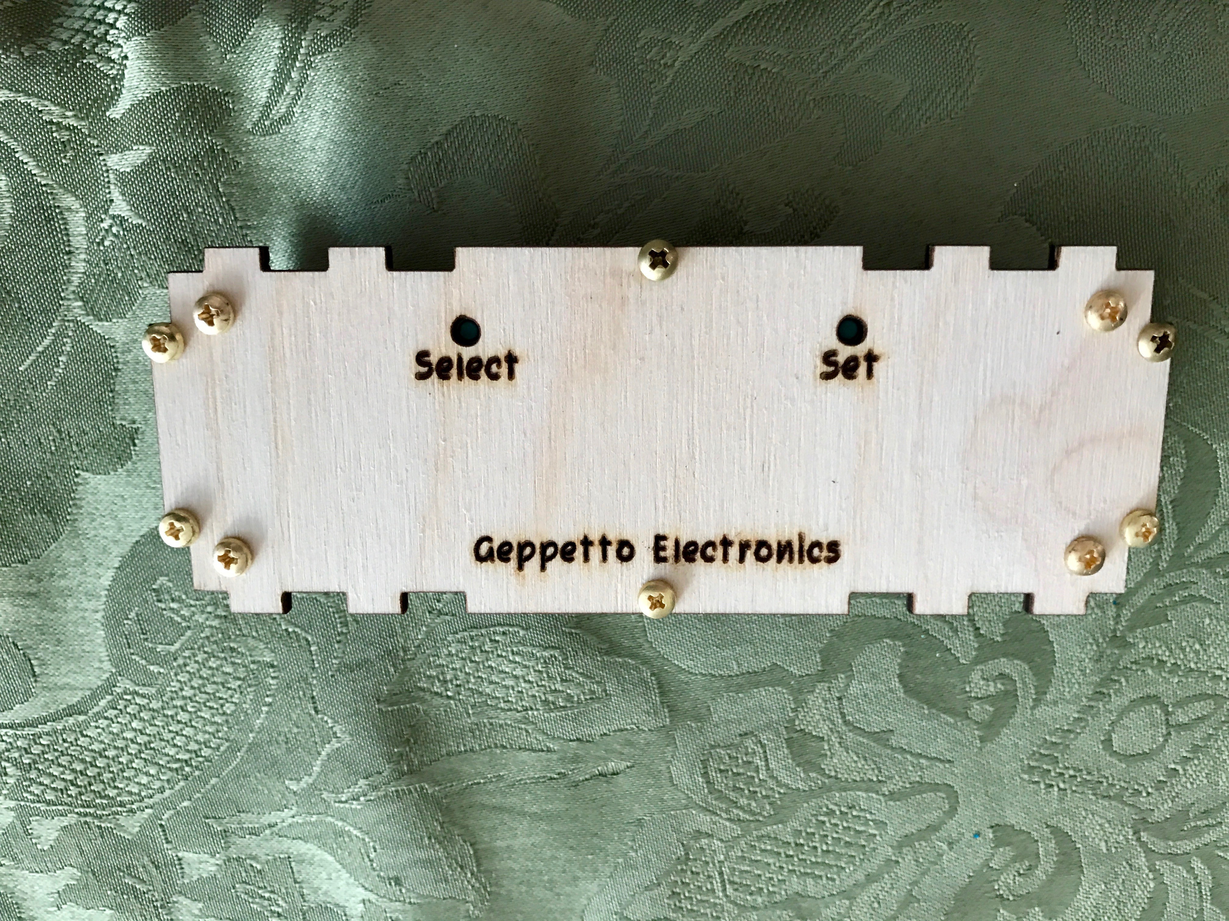
Install a screw in each of the remaining holes on the back panel and loosely thread a nut onto each only a single turn. The nut goes on the inside and the bolt head on the outside.
![]()
GPS Clock
A simple desk clock that gets extremely accurate time from GPS
Discussions
Become a Hackaday.io Member
Create an account to leave a comment. Already have an account? Log In.
This is the only place where I found instructions about this clock. Nothing was included in the delivery package, and there was NOTHING to guide me online to a manual of any kind. While I could figure out most of the settings, I still have no idea what "nC" setting means. The clock works fine, I intend to demonstrate to my computer club, but it is disappointing that a simple manual was not a part of the voluminous information about this product.
Are you sure? yes | no
The "nC" is the SNR display screen. There's nothing to set there, it's just a display screen. I talked about it in this project log: https://hackaday.io/project/18501-gps-clock/log/176299-new-feature-snr-report-screen
You're correct that there is no documentation other than this project overall. It's something I need to sit down and do, but haven't had a chance to do.
Are you sure? yes | no