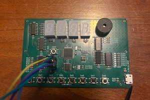
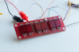
GPS time information is often precise down to the tens of nano-seconds. But if all you want to do is display time for humans, you probably would be satisfied with 4 orders of magnitude less precision, which is what this design achieves - 125 µs accuracy (with v5 hardware) with 100 ms granularity.
Over the course of the project, the clock has undergone a number of design revisions. The original design paired an ATTiny841 with a MAX6951 display driver. The 6951 connects to up to 8 seven-segment common cathode LED display digits (with decimal). This project is going to use 7 of them (6 large and 1 small for the 10th of a second digit), plus two LEDs for AM and PM, 4 for two colons between the 3 large groups, and a FIX LED from the GPS module. There are also two pushbuttons for parameter setting (timezone, DST config and display brightness).
The GPS module has a bidirectional UART and a PPS output. What complicates things just slightly is that the NMEA timecodes on the serial port describe the current second, meaning they happen just after the PPS signal. The serial codes aren't precise enough to do more than name the current second. Actual timing needs to come from the PPS signal. So the serial data needs to have a second added to it, and the result is stored in a buffer in RAM. The PPS interrupt transfers that buffer to the display chip. For tenths of a second, a timer in the controller is used for interpolation. The correct counting rate is determined by counting how many timer ticks occur between adjacent PPS interrupts and dividing that by 10. The timer runs from the controller's RC oscillator, configured for 8 MHz, with a divide-by-8 prescale - so approximately 1 MHz. The controller has interrupt handlers for timer overflow and input capture (for the PPS). The overflow interrupt increments a high order word, allowing us to keep a 32 bit counter. Even at a 1 MHz counting rate, it takes more than an hour to overflow a 32 bit counter, and that gives us microsecond measurement granularity. The RC oscillator's short term stability should be good enough for the purpose, and its stability beyond 2 seconds is mooted by the way it's being used.
The 6951 chip communicates with SPI. It requires a chip select line to be driven low and then 16 bits of data is clocked in. The write format is 8 bits of address and 8 bits of data. The chip has a bunch of registers inside that allow the display to be fully configured and even dimmed. The chip has a resistor that's used to configure the chip for constant-current for each LED segment to insure correct brightness. The chip's maximum SPI clock speed is over 20 MHz, and the highest SPI rate we can use with an 8 MHz ATTiny is 4 MHz, so we can run it flat out without worry. Our accuracy claim (~200 µs) stems from the fact that a full display update over SPI takes approximately 70 µs start to finish, and that happens in the PPS capture interrupt handler once a second that takes around 100 µs before the display updates commence (we do go to the trouble of updating the least significant digits first so that hopefully most of the time the only actual changes take place much faster). The accuracy of the tenth updates is likely much better, but keep in mind that their timing is estimated via interpolation, so that's based on the stability of the 8 MHz RC oscillator in the controller over τ 2s.
The brains of the clock is an ATTiny841, simply because I have a bunch of them and they have a UART (actually, two). It runs from the internal 8 MHz oscillator. The entire circuit runs from a 3.3 volt supply, so 12 MHz is the maximum frequency that could be used, but that would require adding an external crystal for no other reason (and rearranging the pins to allow the crystal to be connected).
The GPS module is the Skytraq Venus838LPx-T timing module. The board has an edge-mount SMA connector for an external antenna, and passes 5v (or 3.3v selectable with a solder jumper) active...
Read more » Nick Sayer

 Zachary Murtishi
 K.C. Lee
 Pierre-Loup M.
 Stephen Holdaway
FYI, Page 18 of MAX6951 datasheet (http://datasheets.maximintegrated.com/en/ds/MAX6950-MAX6951.pdf) mentions that is has a character rom so this would count against you much like the rules said hd44870 LCDs' would. Judging by their diagram it is 8 bit address an d8 bit data for a 256 byte total.