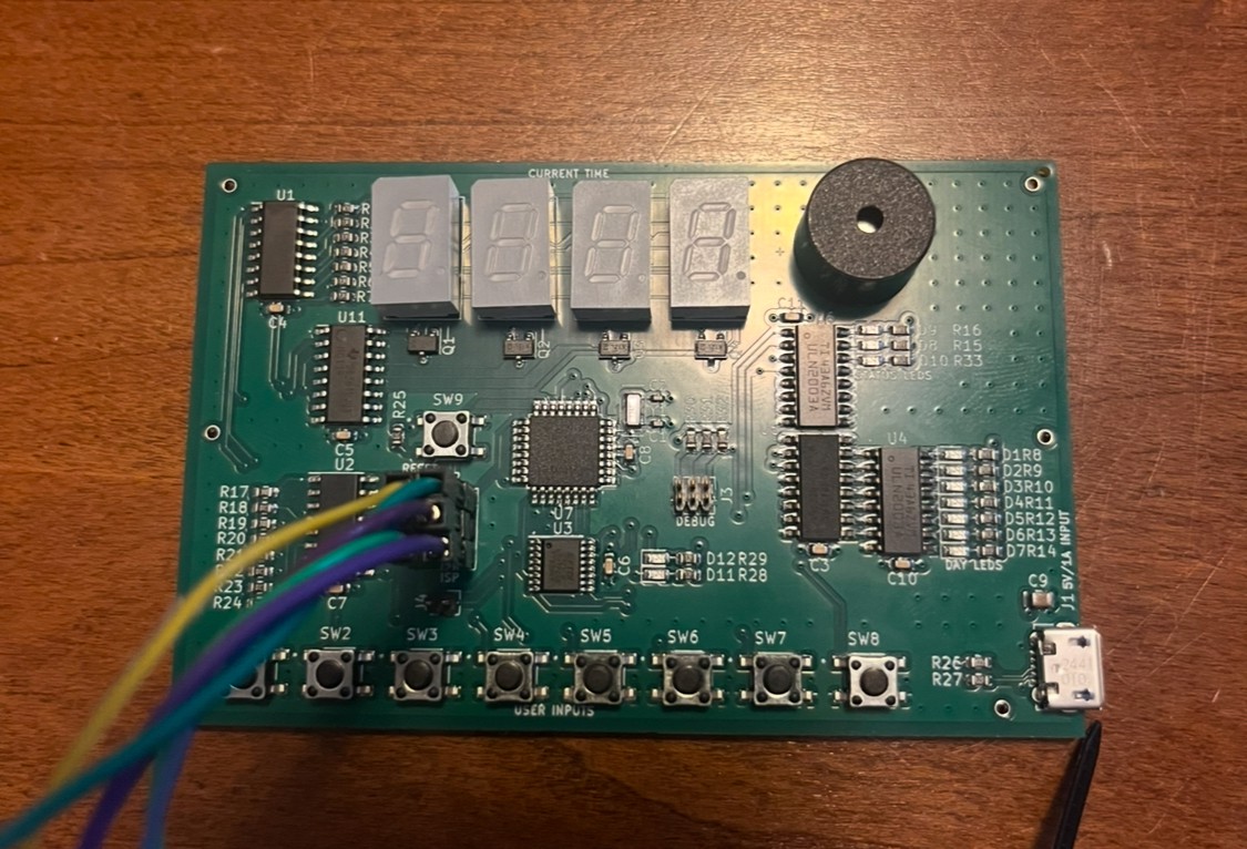
4-layer PCB (HASL finish), manufactured and mostly assembled by JLCPCB
The ATmega328PB microcontroller is programmed through ISP using a PICkit5. MPLAB X is used as an IDE with avr-gcc as the C compiler.
This is a pretty simple clock I designed around an ATmega328PB MCU. The actual timekeeping is performed by pairing a 32.768 kHz crystal with the asynchronous Timer2 to generate a ~1s timekeeping interrupt (increment seconds). As the oscillator pins are occupied by the 32 kHz crystal, the MCU runs off of the 8 MHz internal oscillator.
This clock has some features I wanted in a clock:
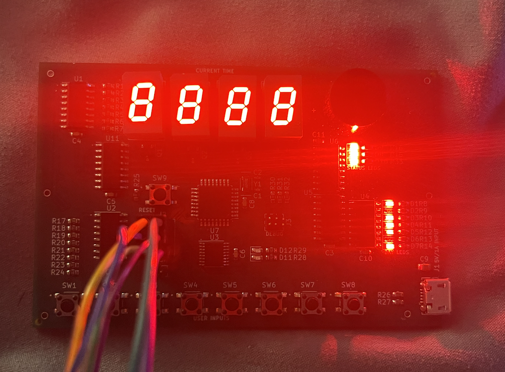
- A simple four-character display shows the current hour and minutes.
- It has a simple alarm feature that allows a single alarm to be set. A buzzer with a 500 Hz tone will sound when this alarm is activated.
- It tracks the day of the week with seven LEDs
- It can display the number of seconds in the current minute (accessible by a user interface setting)
- It can switch between AM/PM and 24 hour display modes (indicated by LEDs as well)
- It has a dimmed display mode that disables all lights on the display during the night time to allow it to be used as an alarm clock and reduce power consumption.
- It has a lamp test mode that lights up all LEDs on the board for testing.
- A Micro-USB interface allows for a simple power interface (have lots of micro USB cables laying around), as well as remote testing of the board's features without the user display through the USB data interface.
A separate 1.024 ms interrupt (dervied from the 8 MHz internal oscillator) increments the system tick value, which is used for several peripheral features i.e. display blinking, button polling interval, alarm period, etc.
A CD4021 shift register is used to interface eight buttons with the MCU. This was done solely to minimize the number of MCU pins required to interface with the buttons. The following functions are accomplished by each button:
SW1 - Increment hour (wraps around)
- In normal mode, the current hour is incremented
- In alarm mode, the alarm hour is incremented
SW2 - Increment minute (wraps around)
- In normal mode, the current minute is incremented (seconds are set to zero)
- In alarm mode, the alarm minute is incremented
SW3 - Change timekeeping mode (AM/PM or 24 hours)
- LED will show the current mode (D8 is on to show PM, D9 is on to show AM, both D8/D9 will be off for 24 hour mode)
SW4 - Change day of the week
- Seven LEDs indicate the day of the week (D1-D7)
- D1 indicates Sunday, D7 indicates Saturday, etc.
SW5 - Set to alarm mode and confirm alarm setting
SW6 - Set /unset alarm - unsetting an alarm during snooze mode will disable the snooze. The alarm must be set after being confirmed - if it is not set, the alarm will not activate when the alarm time is reached.
SW7 - Dim the display. Once the display is dimmed, any button (except for SW8) will exit the dimmed mode.
SW8 - Show the number of seconds in the current minute. If display is dimmed, SW8 will activate the lamp test. Press any button to leave the lamp test function.
When alarm is going off - all buttons except for SW8 will "snooze" the alarm, or push back the alarm another five minutes. SW8 will simply disable the alarm for the next day, when it will activate again. When the snoozed alarm goes off again, SW8 may disable it - any other switch will push it back another five minutes.
As the ATmega328PB has no native USB interface, I paired it with an FT230X to allow it to communicate with an external host PC for remote configuration. I chose a baud rate 38400 bps to minimize the error associated with using an 8 MHz internal oscillator. The following characters may be sent:
All commands (except for TEST) will return an ERROR if sent with incorrect parameters or when the current action cannot be performed (i.e. clock is already set to the desired feature or data is out of range). Otherwise, OK will be returned, except for QUERY / 'A' , which will return data.
'A' - queries the current time. Returns the current time...
Read more » Zachary Murtishi


 Ken Yap
 Nick Sayer
Interesting concept but seems a waste of the MCU computing power to do in hardware tasks like 7 segment decoding easily done in firmware. If you're short of GPIO pins port expander ICs would alleviate that problem. Or use an AVR model with more pins.